EP0915550A1 - Moteur électrique avec moyens pour éviter la surcharge thermique - Google Patents
Moteur électrique avec moyens pour éviter la surcharge thermique Download PDFInfo
- Publication number
- EP0915550A1 EP0915550A1 EP98630054A EP98630054A EP0915550A1 EP 0915550 A1 EP0915550 A1 EP 0915550A1 EP 98630054 A EP98630054 A EP 98630054A EP 98630054 A EP98630054 A EP 98630054A EP 0915550 A1 EP0915550 A1 EP 0915550A1
- Authority
- EP
- European Patent Office
- Prior art keywords
- electric motor
- thermal
- switching means
- coil
- windings
- Prior art date
- Legal status (The legal status is an assumption and is not a legal conclusion. Google has not performed a legal analysis and makes no representation as to the accuracy of the status listed.)
- Withdrawn
Links
- 238000004804 winding Methods 0.000 claims abstract description 70
- 238000004891 communication Methods 0.000 claims abstract description 19
- 238000000034 method Methods 0.000 claims abstract description 14
- 238000002955 isolation Methods 0.000 claims description 3
- 238000011144 upstream manufacturing Methods 0.000 claims description 2
- 238000010420 art technique Methods 0.000 description 9
- 238000010586 diagram Methods 0.000 description 4
- 230000004044 response Effects 0.000 description 2
- 238000010276 construction Methods 0.000 description 1
- 238000010292 electrical insulation Methods 0.000 description 1
- 230000004043 responsiveness Effects 0.000 description 1
Images

Classifications
-
- H—ELECTRICITY
- H02—GENERATION; CONVERSION OR DISTRIBUTION OF ELECTRIC POWER
- H02H—EMERGENCY PROTECTIVE CIRCUIT ARRANGEMENTS
- H02H7/00—Emergency protective circuit arrangements specially adapted for specific types of electric machines or apparatus or for sectionalised protection of cable or line systems, and effecting automatic switching in the event of an undesired change from normal working conditions
- H02H7/08—Emergency protective circuit arrangements specially adapted for specific types of electric machines or apparatus or for sectionalised protection of cable or line systems, and effecting automatic switching in the event of an undesired change from normal working conditions for dynamo-electric motors
- H02H7/085—Emergency protective circuit arrangements specially adapted for specific types of electric machines or apparatus or for sectionalised protection of cable or line systems, and effecting automatic switching in the event of an undesired change from normal working conditions for dynamo-electric motors against excessive load
- H02H7/0852—Emergency protective circuit arrangements specially adapted for specific types of electric machines or apparatus or for sectionalised protection of cable or line systems, and effecting automatic switching in the event of an undesired change from normal working conditions for dynamo-electric motors against excessive load directly responsive to abnormal temperature by using a temperature sensor
Definitions
- the present invention relates to an electric motor having means for preventing thermal overload of the coil windings in the motor, and a method for preventing thermal overload conditions in electric motors.
- Fig. 1 shows an example of a prior art technique for providing such protection.
- Fig. 1 shows a motor 1 having three phase windings 2a, 2b and 2c.
- a thermostat 3 controls application of power from a power source 10 to the windings of the motor via contactor switches 5 of a contactor coil 6.
- a control power source 4 is also shown.
- a bimetallic internal overload line breaker 7 is provided both in thermal contact and electrical communication with the windings of the motor 1.
- line breaker 7 is in physical contact with the windings of the motor so as to sense the temperature thereof, and is also in electrical communication with the windings since line current provided by power source 10 passes through the line breaker.
- a typical example of such an internal line breaker is that provided by Texas Instruments under product designation MWJ.
- Fig. 2 shows another prior art construction of an overload protection circuit for an electric motor.
- a calibrated circuit breaker with contacts 8a, 8b and 8c are provided in the supply lines that power the three phase windings of the electric motor.
- These circuit breakers are sized to handle the locked rotor current of the electric motor, and calibrated to trip at a specific overload current. They are thus designed only to sense the current flowing to the three phase windings of the coil. As the current draw increases, the coil windings heat up. After the current exceeds a preset level, the circuit breaker will trip and cut off power to the electric motor.
- Another prior art technique employs thermistors embedded in the coil windings of the electric motor.
- An electronic module is employed to continuously sense the resistance of the thermistors to in turn sense changes in temperature of the motor windings. While this technique provides a very accurate determination of winding temperature, it is relatively expensive.
- the electric motor according to the present invention includes at least one coil winding, a power supply for energizing the coil winding, and control means for controlling power supplied to the coil winding.
- the control means includes thermal switching means, preferably bimetallic switches, arranged in thermal communication with the coil winding such that the thermal switching means can quickly and accurately sense changes in coil winding temperature.
- the thermal switching means is also electrically isolated from the coil windings (i.e., the line current to the windings does not pass through the thermal switching means), to thereby allow for a substantial reduction in the size and mass of the thermal switching means. This reduction facilitates the extremely quick response time of the thermal switching means.
- thermo communication means in contact with, but shielded by a non-heat-insulating layer, such as a layer of electrical insulation.
- a bimetallic switch is in "thermal communication" with the windings of an electric motor if the heat created by the windings can pass easily and quickly to the switch through the interposed electrically insulating layer.
- electrically isolated or “electrical isolation” as used herein mean that the bimetallic switch is not in direct series contact with the windings of the coil (i.e., the line current supplied to the windings does not pass though the bimetallic switches).
- the present invention makes use of extremely sensitive, but also extremely cost effective, bimetallic switches that are positioned in thermal communication with at least one coil winding of an electric motor, but in electrical isolation with all of the coil windings in the motor, in order to sense the temperature of the coil windings in a quick and accurate manner.
- the present invention provides the same thermal overload protection as the thermistor-based prior art technique discussed above, but at a huge cost savings.
- the electric motor of the present invention is associated with a contactor coil and a power supply.
- the thermal switching means can be located, electrically, either between the contactor coil and the power supply, or upstream of the power supply.
- the method of the present invention provides for protection against thermal overload in an electric motor by positioning thermal switching means in thermal communication with at least one coil winding of the electric motor, and electrically isolating the thermal switching means from all coil windings of the electric motor.
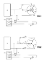
- circuit diagram in Fig. 3 employs the same reference numerals as Figs. 1 and 2 to identify similar components. While the present invention will be explained with reference to a fan motor for a heat pump, it is to be understood that the teachings of the present invention apply to any electric motor, single phase or three phase.
- bimetallic switches 9a and 9b are embedded in at least two coil windings of a three phase electric motor and are, therefore, in thermal contact therewith.
- the bimetallic switches are not in electrical communication with any of the coil windings, in that line current from the power supply 10 is not first passed through the bimetallic switches before entering the windings of the electric motor.
- the mass of the bimetallic switches can be reduced substantially, because those switches are not required to handle the current loads passed through the windings of the motor.
- the responsiveness of the bimetallic switches to changes in temperatures of the coil windings is significantly increased as a result of their reduced mass.
- An example of a bimetallic switch that is useful in the present invention is the 8mm bimetallic switch manufactured by Texas Instruments.
- the bimetallic switches being in thermal communication with the coil windings of the electric motor, and being of relatively small mass, are able to sense temperature changes in the coil windings very quickly and accurately. If the coil windings become too hot, then the bimetallic switches break the circuit and stop the supply of power to contactor coil 6 and thus disengage the motor.
- Fig. 4 shows another embodiment of the present invention which is similar to that shown in Fig. 3, except that the bimetallic switches 9a and 9b are connected to the hot side of control power supply 4. In this way, if the coil windings over-heat, the bimetallic switches cut off power to the entire system, including the power not only to the motor, but also to the associated compressor (not shown) of the heat pump system.
- the present invention provides a significant improvement in the area of thermal overload protection for electric motors, in that it provides the sensing accuracy attributable to the thermistor-based prior art technique discussed above, but at a 35 to 50-fold cost reduction. Moreover, the present invention is also more accurate and less expensive than the first and second prior art techniques discussed above.
Landscapes
- Protection Of Generators And Motors (AREA)
Applications Claiming Priority (2)
| Application Number | Priority Date | Filing Date | Title |
|---|---|---|---|
| US96371197A | 1997-11-04 | 1997-11-04 | |
| US963711 | 1997-11-04 |
Publications (1)
| Publication Number | Publication Date |
|---|---|
| EP0915550A1 true EP0915550A1 (fr) | 1999-05-12 |
Family
ID=25507597
Family Applications (1)
| Application Number | Title | Priority Date | Filing Date |
|---|---|---|---|
| EP98630054A Withdrawn EP0915550A1 (fr) | 1997-11-04 | 1998-10-09 | Moteur électrique avec moyens pour éviter la surcharge thermique |
Country Status (5)
| Country | Link |
|---|---|
| EP (1) | EP0915550A1 (fr) |
| JP (1) | JPH11206002A (fr) |
| KR (1) | KR19990044980A (fr) |
| CN (1) | CN1068993C (fr) |
| BR (1) | BR9804321A (fr) |
Cited By (5)
| Publication number | Priority date | Publication date | Assignee | Title |
|---|---|---|---|---|
| DE19948396A1 (de) * | 1999-10-07 | 2001-05-10 | Roland Martin | Temperaturüberwachungs- und Sicherheits-Modul |
| DE10019736A1 (de) * | 2000-04-20 | 2001-10-25 | Mannesmann Vdo Ag | Sicherheitsschaltung |
| EP1303021A3 (fr) * | 2001-09-17 | 2003-09-17 | Hanning Elektro-Werke GmbH & Co. KG | Moteur à commande électronique, à vitesse variable |
| CN100446375C (zh) * | 2004-12-10 | 2008-12-24 | 哈尔滨工业大学 | 一种交流电动机热过载保护方法 |
| EP2830178A1 (fr) * | 2013-07-22 | 2015-01-28 | ebm-papst Mulfingen GmbH & Co. KG | Circuit de protection thermique et de régulation de puissance de moteurs électriques |
Families Citing this family (1)
| Publication number | Priority date | Publication date | Assignee | Title |
|---|---|---|---|---|
| CN103414160A (zh) * | 2013-07-15 | 2013-11-27 | 国家电网公司 | 一种电机自动保护控制装置 |
Citations (6)
| Publication number | Priority date | Publication date | Assignee | Title |
|---|---|---|---|---|
| US1947078A (en) * | 1931-11-11 | 1934-02-13 | Westinghouse Electric & Mfg Co | Motor thermal relay |
| US2304599A (en) * | 1940-08-03 | 1942-12-08 | Wagner Electric Corp | Alternating current motor |
| US2389073A (en) * | 1943-04-23 | 1945-11-13 | Honeywell Regulator Co | Overload protection for refrigeration systems |
| GB865649A (en) * | 1957-08-21 | 1961-04-19 | Westinghouse Electric Corp | Improvements in or relating to over-temperature protective systems for electric motors |
| US3200274A (en) * | 1963-03-14 | 1965-08-10 | Wagner Electric Corp | Thermal protection means for an electric motor |
| GB1013877A (en) * | 1963-09-06 | 1965-12-22 | Crompton Parkinson Ltd | Improvements relating to electric motors |
Family Cites Families (1)
| Publication number | Priority date | Publication date | Assignee | Title |
|---|---|---|---|---|
| US5343613A (en) * | 1993-01-27 | 1994-09-06 | Sundstrand Corporation | Method of installing thermal protection for an electric motor stator |
-
1998
- 1998-10-09 EP EP98630054A patent/EP0915550A1/fr not_active Withdrawn
- 1998-10-15 JP JP10292681A patent/JPH11206002A/ja active Pending
- 1998-10-29 BR BR9804321A patent/BR9804321A/pt not_active IP Right Cessation
- 1998-11-03 KR KR1019980047031A patent/KR19990044980A/ko not_active Ceased
- 1998-11-04 CN CN98124118A patent/CN1068993C/zh not_active Expired - Fee Related
Patent Citations (6)
| Publication number | Priority date | Publication date | Assignee | Title |
|---|---|---|---|---|
| US1947078A (en) * | 1931-11-11 | 1934-02-13 | Westinghouse Electric & Mfg Co | Motor thermal relay |
| US2304599A (en) * | 1940-08-03 | 1942-12-08 | Wagner Electric Corp | Alternating current motor |
| US2389073A (en) * | 1943-04-23 | 1945-11-13 | Honeywell Regulator Co | Overload protection for refrigeration systems |
| GB865649A (en) * | 1957-08-21 | 1961-04-19 | Westinghouse Electric Corp | Improvements in or relating to over-temperature protective systems for electric motors |
| US3200274A (en) * | 1963-03-14 | 1965-08-10 | Wagner Electric Corp | Thermal protection means for an electric motor |
| GB1013877A (en) * | 1963-09-06 | 1965-12-22 | Crompton Parkinson Ltd | Improvements relating to electric motors |
Cited By (5)
| Publication number | Priority date | Publication date | Assignee | Title |
|---|---|---|---|---|
| DE19948396A1 (de) * | 1999-10-07 | 2001-05-10 | Roland Martin | Temperaturüberwachungs- und Sicherheits-Modul |
| DE10019736A1 (de) * | 2000-04-20 | 2001-10-25 | Mannesmann Vdo Ag | Sicherheitsschaltung |
| EP1303021A3 (fr) * | 2001-09-17 | 2003-09-17 | Hanning Elektro-Werke GmbH & Co. KG | Moteur à commande électronique, à vitesse variable |
| CN100446375C (zh) * | 2004-12-10 | 2008-12-24 | 哈尔滨工业大学 | 一种交流电动机热过载保护方法 |
| EP2830178A1 (fr) * | 2013-07-22 | 2015-01-28 | ebm-papst Mulfingen GmbH & Co. KG | Circuit de protection thermique et de régulation de puissance de moteurs électriques |
Also Published As
| Publication number | Publication date |
|---|---|
| CN1068993C (zh) | 2001-07-25 |
| JPH11206002A (ja) | 1999-07-30 |
| BR9804321A (pt) | 1999-12-21 |
| KR19990044980A (ko) | 1999-06-25 |
| CN1216412A (zh) | 1999-05-12 |
Similar Documents
| Publication | Publication Date | Title |
|---|---|---|
| CA2085202C (fr) | Protection d'enroulement de demarrage a coefficient de temperature positif | |
| EP1912238B1 (fr) | Interrupteur de circuit comprenant un détecteur de courant à fil de dérivation et un processeur ayant une fonction prédictive de surcharge thermique | |
| CN104332954B (zh) | 用于对电机进行热保护及功率调节的电路 | |
| US3697863A (en) | Overcurrent protection system and sensor used therewith | |
| US3079524A (en) | Protector for dynamoelectric machines | |
| KR101904578B1 (ko) | 부하를 보호하기 위한 장치 및 방법 | |
| US3794950A (en) | Overcurrent protection system and sensor used therewith | |
| US3753070A (en) | Protective circuit for electric motors | |
| EP0915550A1 (fr) | Moteur électrique avec moyens pour éviter la surcharge thermique | |
| KR20010074905A (ko) | 전기 부품을 통과하는 전류의 제한 방법 및 제한 장치 | |
| US6570129B1 (en) | Protection device for dual stage power supply | |
| US5546262A (en) | Electronic protection device | |
| US3280373A (en) | Over-temperature protection system having means for simulating the temperature rise rate of a dynamoelectric machine and winding | |
| US3209206A (en) | Overtemperature protected apparatus | |
| US5822164A (en) | Pre-engineered combination starter for multiple motor sizes | |
| US4994651A (en) | Solid state temperature dependent direct voltage interrupter for a heater circuit | |
| AU689161B2 (en) | Three phase throttle current technique | |
| MXPA98009152A (es) | Motor electrico medios para prevenir la sobrecarga termica | |
| US2497684A (en) | Protective system for dynamoelectric machines | |
| US2482955A (en) | Circuit breaker | |
| US2710373A (en) | Protective circuit for three-phase motors | |
| EP1966880B1 (fr) | Moteur | |
| FI62612B (fi) | Anordning foer temperaturbegraensning vid kanalvaermare | |
| EP0449822B1 (fr) | Dispositif de commande et de protection electronique | |
| RU2192698C1 (ru) | Устройство для защиты электродвигателей |
Legal Events
| Date | Code | Title | Description |
|---|---|---|---|
| PUAI | Public reference made under article 153(3) epc to a published international application that has entered the european phase |
Free format text: ORIGINAL CODE: 0009012 |
|
| AK | Designated contracting states |
Kind code of ref document: A1 Designated state(s): DE ES FR GB IT |
|
| AX | Request for extension of the european patent |
Free format text: AL;LT;LV;MK;RO;SI |
|
| AKX | Designation fees paid |
Free format text: DE ES FR GB IT |
|
| 17P | Request for examination filed |
Effective date: 20000117 |
|
| STAA | Information on the status of an ep patent application or granted ep patent |
Free format text: STATUS: THE APPLICATION IS DEEMED TO BE WITHDRAWN |
|
| 18D | Application deemed to be withdrawn |
Effective date: 20020501 |