EP2830178A1 - Circuit de protection thermique et de régulation de puissance de moteurs électriques - Google Patents
Circuit de protection thermique et de régulation de puissance de moteurs électriques Download PDFInfo
- Publication number
- EP2830178A1 EP2830178A1 EP14171711.6A EP14171711A EP2830178A1 EP 2830178 A1 EP2830178 A1 EP 2830178A1 EP 14171711 A EP14171711 A EP 14171711A EP 2830178 A1 EP2830178 A1 EP 2830178A1
- Authority
- EP
- European Patent Office
- Prior art keywords
- temperature
- ptc
- dependent resistor
- winding
- circuit
- Prior art date
- Legal status (The legal status is an assumption and is not a legal conclusion. Google has not performed a legal analysis and makes no representation as to the accuracy of the status listed.)
- Granted
Links
Images
Classifications
-
- H—ELECTRICITY
- H02—GENERATION; CONVERSION OR DISTRIBUTION OF ELECTRIC POWER
- H02P—CONTROL OR REGULATION OF ELECTRIC MOTORS, ELECTRIC GENERATORS OR DYNAMO-ELECTRIC CONVERTERS; CONTROLLING TRANSFORMERS, REACTORS OR CHOKE COILS
- H02P3/00—Arrangements for stopping or slowing electric motors, generators, or dynamo-electric converters
- H02P3/06—Arrangements for stopping or slowing electric motors, generators, or dynamo-electric converters for stopping or slowing an individual dynamo-electric motor or dynamo-electric converter
-
- H—ELECTRICITY
- H02—GENERATION; CONVERSION OR DISTRIBUTION OF ELECTRIC POWER
- H02H—EMERGENCY PROTECTIVE CIRCUIT ARRANGEMENTS
- H02H5/00—Emergency protective circuit arrangements for automatic disconnection directly responsive to an undesired change from normal non-electric working conditions with or without subsequent reconnection
- H02H5/04—Emergency protective circuit arrangements for automatic disconnection directly responsive to an undesired change from normal non-electric working conditions with or without subsequent reconnection responsive to abnormal temperature
-
- H—ELECTRICITY
- H02—GENERATION; CONVERSION OR DISTRIBUTION OF ELECTRIC POWER
- H02H—EMERGENCY PROTECTIVE CIRCUIT ARRANGEMENTS
- H02H7/00—Emergency protective circuit arrangements specially adapted for specific types of electric machines or apparatus or for sectionalised protection of cable or line systems, and effecting automatic switching in the event of an undesired change from normal working conditions
- H02H7/08—Emergency protective circuit arrangements specially adapted for specific types of electric machines or apparatus or for sectionalised protection of cable or line systems, and effecting automatic switching in the event of an undesired change from normal working conditions for dynamo-electric motors
- H02H7/085—Emergency protective circuit arrangements specially adapted for specific types of electric machines or apparatus or for sectionalised protection of cable or line systems, and effecting automatic switching in the event of an undesired change from normal working conditions for dynamo-electric motors against excessive load
- H02H7/0852—Emergency protective circuit arrangements specially adapted for specific types of electric machines or apparatus or for sectionalised protection of cable or line systems, and effecting automatic switching in the event of an undesired change from normal working conditions for dynamo-electric motors against excessive load directly responsive to abnormal temperature by using a temperature sensor
-
- H—ELECTRICITY
- H02—GENERATION; CONVERSION OR DISTRIBUTION OF ELECTRIC POWER
- H02H—EMERGENCY PROTECTIVE CIRCUIT ARRANGEMENTS
- H02H9/00—Emergency protective circuit arrangements for limiting excess current or voltage without disconnection
- H02H9/02—Emergency protective circuit arrangements for limiting excess current or voltage without disconnection responsive to excess current
- H02H9/026—Current limitation using PTC resistors, i.e. resistors with a large positive temperature coefficient
-
- H—ELECTRICITY
- H02—GENERATION; CONVERSION OR DISTRIBUTION OF ELECTRIC POWER
- H02P—CONTROL OR REGULATION OF ELECTRIC MOTORS, ELECTRIC GENERATORS OR DYNAMO-ELECTRIC CONVERTERS; CONTROLLING TRANSFORMERS, REACTORS OR CHOKE COILS
- H02P29/00—Arrangements for regulating or controlling electric motors, appropriate for both AC and DC motors
- H02P29/02—Providing protection against overload without automatic interruption of supply
-
- H—ELECTRICITY
- H02—GENERATION; CONVERSION OR DISTRIBUTION OF ELECTRIC POWER
- H02P—CONTROL OR REGULATION OF ELECTRIC MOTORS, ELECTRIC GENERATORS OR DYNAMO-ELECTRIC CONVERTERS; CONTROLLING TRANSFORMERS, REACTORS OR CHOKE COILS
- H02P29/00—Arrangements for regulating or controlling electric motors, appropriate for both AC and DC motors
- H02P29/60—Controlling or determining the temperature of the motor or of the drive
- H02P29/64—Controlling or determining the temperature of the winding
-
- H—ELECTRICITY
- H02—GENERATION; CONVERSION OR DISTRIBUTION OF ELECTRIC POWER
- H02K—DYNAMO-ELECTRIC MACHINES
- H02K23/00—DC commutator motors or generators having mechanical commutator; Universal AC/DC commutator motors
- H02K23/26—DC commutator motors or generators having mechanical commutator; Universal AC/DC commutator motors characterised by the armature windings
- H02K23/36—DC commutator motors or generators having mechanical commutator; Universal AC/DC commutator motors characterised by the armature windings having two or more windings; having two or more commutators; having two or more stators
Definitions
- the present invention relates to a circuit for thermal protection and for power control as a function of a current winding temperature of strand windings of an electric motor, comprising on the one hand a winding temperature of the strand windings measuring temperature monitor switch, upon reaching a certain winding temperature, the switching temperature, a shutdown of the by the Windings flowing winding current causes, as well as a the string windings associated temperature-dependent resistance, which causes a performance reduction of the engine performance by reaching a certain winding temperature by a resistance increase.
- the protection of a three-phase electric motor against thermal overload is known to be achieved by three temperature-control switch, which is preferably bimetal switch.
- the temperature of each motor string is sampled with its own temperature monitor, in order to achieve unbalanced temperature increases, eg. B. to detect by a winding insulation damage.
- the three temperature monitor switches are connected in series. When the switching temperature of one of the temperature monitor switches is exceeded, this opens. The interruption is detected in an electronic evaluation system and triggered the action necessary for the respective protection concept. This is typically the turning off of the winding current flowing through the strand windings.
- the temperature-increasing resistance value of the temperature-dependent resistor is used to measure the current winding temperature, for. B. the voltage drop across the temperature-dependent resistance at impressing a constant current is measured. If the temperature is too high, the power to the motor will be reduced. Due to the assumption that the temperatures in the three winding phases are approximately the same when the motor is functioning properly, only a temperature-dependent resistor is used to reduce the effort. In order to be able to evaluate the series connection of the three temperature monitor switches by means of evaluation electronics, two connections to the signal electronics are required. Similarly, the evaluation of the temperature-dependent resistor by the evaluation electronics two connections to the electronics needed. So a total of four connections between the electric motor and the evaluation electronics are required. This results in an increased circuit and component costs.
- the invention is based on the object to reduce the circuit complexity for the thermal monitoring and power control of electric motors.
- one of the strand windings has the temperature-dependent resistance in the monitored electric motor with multiple strand windings and the other strand winding or the other strand windings each have a temperature monitor switch, wherein the temperature-dependent resistor and the or the temperature monitor switch connected in series to a voltage source.
- the series connection of the temperature-dependent resistor and the temperature monitor switch is connected to an evaluation electronics in such a way that the series connection impresses a constant current and a voltage drop across the series connection is measured and according to the amount of voltage drop, the motor power is reduced or the motor current is interrupted.
- each winding strand can furthermore be scanned separately for thermal overload and, in addition, the current temperature of a winding strand can be measured with the same circuit.
- the temperature-dependent resistor is used according to the invention both for temperature control and for shutdown at excess temperature.
- the evaluation for the over-temperature protection is carried out, for example, such that the evaluation electronics causes the shutdown of the electric motor by the evaluation electronics upon reaching a dependent of the selection of the respective temperature-dependent resistance and the height of the constant current voltage value.
- the respective temperature switch opens and the voltage across the series connection reaches its maximum value, ie a value above the switch-off threshold of the temperature-dependent resistor.
- the engine is switched off.
- the resistance value of the temperature-dependent resistor is measured before reaching the shutdown temperature of the temperature monitor switch and so the current temperature can be determined. Due to the circuit according to the invention, when a temperature switch opens, the evaluation of the temperature is no longer necessary because the motor is stopped by opening the temperature monitor switch. When cooling the electric motor of the respective temperature switch, which is open, turned on again.
- the electronics detects the voltage value at the series connection according to the invention, which is now below the switch-off threshold, and puts the motor back into operation. Accordingly, according to the invention only a total of two connections to the electronic evaluation necessary. Thus, according to the invention, only one circuit part is required and not two different evaluation circuits. In addition, a temperature monitor switch is saved according to the invention.
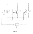
- Fig. 1 is the connection diagram of an electric motor with three motor windings W1, W2 and W3 shown, which are connected via the lines L1 to L3 to a power supply.
- the motor is operated here, for example, in star connection.
- the windings are assigned temperature monitors TW1 and TW2 and a temperature-dependent resistor PTC, which are connected in series in any order.
- the temperature-dependent resistor PTC is in particular a PTC resistor.
- each winding strand can be scanned separately for thermal overload and in addition can be measured with the same circuit, the current temperature of a winding strand.
- the temperature-dependent resistor PTC then serves both for temperature control and for shutdown at excess temperature of this strand.
- the evaluation for the over-temperature protection takes place, for example, such that the evaluating electronics impresses a constant current into the series connection of two temperature monitors TW1 and TW2 and a temperature-dependent resistor PTC and measures the voltage drop across the series circuit.
- the shutdown of the engine is carried out by the signal electronics.
- the resistance of the temperature-dependent resistor PTC increases. If the voltage across the series connection of the two temperature monitors TW1 and TW2 and the temperature-dependent resistor PTC is too high, the electronics switch off the motor. If one of the two temperature monitors TW1, TW2 reaches its switch-off temperature before reaching the voltage threshold of the temperature-dependent resistor PTC, this temperature monitor opens TW1, TW2, and the voltage across the series connection is maximized, ie. H. in any case above the switch-off threshold of the temperature-dependent resistor PTC. The engine is switched off.
- the resistance value of the temperature-dependent resistor PTC can be measured and the current temperature can be determined.
- the invention is not limited to the illustrated and described embodiment, but also includes all the same in the context of the invention-acting embodiments. Furthermore, the invention has hitherto not been limited to the feature combinations defined in the claims, but may also be defined by any other combination of specific features of all individual features disclosed overall. This means that in principle virtually every individual feature of the claims can be omitted or replaced by at least one individual feature disclosed elsewhere in the application. In this respect, the claims are to be understood merely as a first formulation attempt for an invention.
Landscapes
- Engineering & Computer Science (AREA)
- Power Engineering (AREA)
- Protection Of Generators And Motors (AREA)
Applications Claiming Priority (1)
| Application Number | Priority Date | Filing Date | Title |
|---|---|---|---|
| DE102013107819.2A DE102013107819A1 (de) | 2013-07-22 | 2013-07-22 | "Schaltung zum thermischen Schutz und zur Leistungsregelung von Elektromotoren" |
Publications (2)
| Publication Number | Publication Date |
|---|---|
| EP2830178A1 true EP2830178A1 (fr) | 2015-01-28 |
| EP2830178B1 EP2830178B1 (fr) | 2015-12-02 |
Family
ID=50897448
Family Applications (1)
| Application Number | Title | Priority Date | Filing Date |
|---|---|---|---|
| EP14171711.6A Active EP2830178B1 (fr) | 2013-07-22 | 2014-06-10 | Circuit de protection thermique et de régulation de puissance de moteurs électriques |
Country Status (6)
| Country | Link |
|---|---|
| US (1) | US9479091B2 (fr) |
| EP (1) | EP2830178B1 (fr) |
| CN (1) | CN104332954B (fr) |
| DE (1) | DE102013107819A1 (fr) |
| ES (1) | ES2563279T3 (fr) |
| PT (1) | PT2830178E (fr) |
Cited By (1)
| Publication number | Priority date | Publication date | Assignee | Title |
|---|---|---|---|---|
| WO2019110588A1 (fr) * | 2017-12-05 | 2019-06-13 | Brose Fahrzeugteile GmbH & Co. Kommanditgesellschaft, Würzburg | Dispositif de protection et procédé de protection d'un réseau haute tension ainsi que système d'entraînement électrique |
Families Citing this family (12)
| Publication number | Priority date | Publication date | Assignee | Title |
|---|---|---|---|---|
| JP6096718B2 (ja) * | 2014-06-13 | 2017-03-15 | ファナック株式会社 | 複数のptcサーミスタを備えた電動機の過熱検出装置 |
| CN104934941B (zh) * | 2015-05-08 | 2018-03-23 | 北京汽车股份有限公司 | 行李箱门锁电机保护方法和系统 |
| JP6493259B2 (ja) | 2016-03-11 | 2019-04-03 | オムロン株式会社 | 温度監視装置、温度監視方法、情報処理プログラム、および記録媒体 |
| DE102016106431A1 (de) | 2016-04-08 | 2017-10-12 | Ebm-Papst Mulfingen Gmbh & Co. Kg | Temperaturüberwachung |
| DE202016101853U1 (de) | 2016-04-08 | 2016-05-04 | Ebm-Papst Mulfingen Gmbh & Co. Kg | Temperaturüberwachung |
| DE102016118493A1 (de) * | 2016-09-29 | 2018-03-29 | Miele & Cie. Kg | Zwei-strängiger Synchronantrieb |
| JP7003606B2 (ja) * | 2017-12-05 | 2022-01-20 | トヨタ自動車株式会社 | ハイブリッド自動車およびこれに搭載される制御装置 |
| DE102018002148A1 (de) * | 2018-03-16 | 2019-09-19 | C. & E. Fein Gmbh | Bohrvorrichtung und Verfahren zum Betreiben einer Bohrvorrichtung |
| CN110987223B (zh) * | 2019-11-27 | 2021-03-16 | 山东航天电子技术研究所 | 一种改进的高精度铂电阻测温电路 |
| CN115552791A (zh) * | 2020-05-08 | 2022-12-30 | 康明斯公司 | 基于温度读数控制电驱动系统 |
| US12415708B2 (en) * | 2020-05-29 | 2025-09-16 | Tk Home Solutions B.V. | Stairlift safety system |
| US20260001206A1 (en) * | 2024-06-26 | 2026-01-01 | Milwaukee Electric Tool Corporation | Systems and methods for power tools with enhanced motor thermal protection |
Citations (4)
| Publication number | Priority date | Publication date | Assignee | Title |
|---|---|---|---|---|
| GB865649A (en) * | 1957-08-21 | 1961-04-19 | Westinghouse Electric Corp | Improvements in or relating to over-temperature protective systems for electric motors |
| DE1513095A1 (de) * | 1965-11-16 | 1969-07-31 | Villamos Berendezes Es Keszule | Schaltungsanordnung mit Halbleiterfuehlern zum Schutz von elektrischen Vorrichtungen gegen UEbertemperaturen |
| US5604476A (en) * | 1992-08-11 | 1997-02-18 | Ellenberger & Poensgen Gmbh | Protective device for an electrical consumer |
| EP0915550A1 (fr) * | 1997-11-04 | 1999-05-12 | Carrier Corporation | Moteur électrique avec moyens pour éviter la surcharge thermique |
Family Cites Families (12)
| Publication number | Priority date | Publication date | Assignee | Title |
|---|---|---|---|---|
| CH338899A (de) * | 1955-09-07 | 1959-06-15 | Leutenegger Friedrich | Schutzschaltungsanordnung, insbesondere für Elektromotoren |
| AT303171B (de) * | 1971-04-05 | 1972-11-10 | Voest Ag | Schaltanordnung zur Überwachung der Wicklungstemperatur von elektrischen Maschinen |
| US5530613A (en) * | 1994-06-01 | 1996-06-25 | Eaton Corporation | Current limiting circuit controller |
| DE102004010959A1 (de) * | 2003-03-10 | 2004-09-23 | Behr Gmbh & Co. Kg | Anordnung zum Schutz vor Überlast eines Elektromotors |
| US7839108B2 (en) * | 2008-01-24 | 2010-11-23 | Gm Global Technology Operations, Inc. | Electric motor stator winding temperature estimation |
| EP2184830B1 (fr) * | 2008-10-13 | 2011-03-09 | Siemens Aktiengesellschaft | Dispositif de surveillance de la température d'un enroulement de courant multiphasé d'une machine électrique |
| CN102052704A (zh) * | 2009-11-09 | 2011-05-11 | 刘定能 | 组合式取暖箱 |
| CN201690221U (zh) * | 2010-05-21 | 2010-12-29 | 无锡市百川科技有限公司 | 马达保护装置 |
| CN202197091U (zh) * | 2011-08-25 | 2012-04-18 | 大连美恒时代科技有限公司 | 一种数字化的电动机综合保护器 |
| CN102540014B (zh) * | 2011-12-22 | 2014-07-16 | 西安四方机电有限责任公司 | 电力电缆的在线实时防盗割装置及方法 |
| CN202586287U (zh) * | 2012-05-15 | 2012-12-05 | 江苏利得尔电机有限公司 | 异步电动机过热保护电路 |
| US9413211B2 (en) * | 2013-03-15 | 2016-08-09 | Nidec Motor Corporation | Multiple speed motor with thermal overload protection |
-
2013
- 2013-07-22 DE DE102013107819.2A patent/DE102013107819A1/de not_active Withdrawn
-
2014
- 2014-06-10 ES ES14171711.6T patent/ES2563279T3/es active Active
- 2014-06-10 PT PT141717116T patent/PT2830178E/pt unknown
- 2014-06-10 EP EP14171711.6A patent/EP2830178B1/fr active Active
- 2014-07-17 US US14/333,717 patent/US9479091B2/en not_active Expired - Fee Related
- 2014-07-18 CN CN201410345285.2A patent/CN104332954B/zh not_active Expired - Fee Related
Patent Citations (4)
| Publication number | Priority date | Publication date | Assignee | Title |
|---|---|---|---|---|
| GB865649A (en) * | 1957-08-21 | 1961-04-19 | Westinghouse Electric Corp | Improvements in or relating to over-temperature protective systems for electric motors |
| DE1513095A1 (de) * | 1965-11-16 | 1969-07-31 | Villamos Berendezes Es Keszule | Schaltungsanordnung mit Halbleiterfuehlern zum Schutz von elektrischen Vorrichtungen gegen UEbertemperaturen |
| US5604476A (en) * | 1992-08-11 | 1997-02-18 | Ellenberger & Poensgen Gmbh | Protective device for an electrical consumer |
| EP0915550A1 (fr) * | 1997-11-04 | 1999-05-12 | Carrier Corporation | Moteur électrique avec moyens pour éviter la surcharge thermique |
Cited By (1)
| Publication number | Priority date | Publication date | Assignee | Title |
|---|---|---|---|---|
| WO2019110588A1 (fr) * | 2017-12-05 | 2019-06-13 | Brose Fahrzeugteile GmbH & Co. Kommanditgesellschaft, Würzburg | Dispositif de protection et procédé de protection d'un réseau haute tension ainsi que système d'entraînement électrique |
Also Published As
| Publication number | Publication date |
|---|---|
| DE102013107819A9 (de) | 2015-05-21 |
| PT2830178E (pt) | 2016-02-26 |
| DE102013107819A8 (de) | 2015-03-26 |
| EP2830178B1 (fr) | 2015-12-02 |
| CN104332954A (zh) | 2015-02-04 |
| CN104332954B (zh) | 2018-11-09 |
| ES2563279T3 (es) | 2016-03-14 |
| US20150022133A1 (en) | 2015-01-22 |
| DE102013107819A1 (de) | 2015-01-22 |
| US9479091B2 (en) | 2016-10-25 |
Similar Documents
| Publication | Publication Date | Title |
|---|---|---|
| DE102013107819A9 (de) | "Schaltung zum thermischen Schutz und zur Leistungsregelung von Elektromotoren" | |
| DE112015001177B4 (de) | Einschaltzustandsstörungs-Erfassungsvorrichtung und Verfahren dafür | |
| DE102015108888B4 (de) | Überhitzungserkennungsvorrichtung für einen Elektromotor, ausgestattet mit mehreren PTC Thermistoren | |
| DE102015107718B4 (de) | Vorrichtung und Verfahren zum Absichern einer Bordnetz-Komponente eines Fahrzeug-Bordnetzes | |
| DE102015121194A1 (de) | Vorrichtung mit integriertem Schutzverlauf und Verfahren | |
| DE102008003786A1 (de) | Verfahren zur Detektion einer thermischen Überlastsituation bei einem Elektrohandwerkzeug | |
| EP3561981A1 (fr) | Procédé de réduction de montée en température dans un élément de commutation recommandable | |
| EP3304667B1 (fr) | Protection anti-échauffement | |
| DE69812361T2 (de) | Festkörperüberstromrelais | |
| DE102016106431A1 (de) | Temperaturüberwachung | |
| EP2961019A1 (fr) | Dispositif de protection contre un courant excessif pour un vehicule automobile, dispositif de connexion electrique et vehicule automobile | |
| BE1026445A1 (de) | Geräteschutzschalter mit intelligenter Grenzwertermittlung | |
| DE102017214205A1 (de) | Steuergerät mit Schaltung und Verfahren zum Kurzschlussschutz von Masseleitungen und Sensoren | |
| EP1994620B1 (fr) | Dispositif de protection et procédé de contrôle de la température d'un appareil | |
| EP2083493A1 (fr) | Relais de surcharge et procédé de fonctionnement d'un tel relais de surcharge | |
| DE3513179C2 (de) | Schutzschaltung für kollektorlose Gleichstrommotoren | |
| BE1027539B1 (de) | Verfahren und Vorrichtung zur Ermittlung der Drehrichtung eines Drehfeldes sowie Hybrid-Motorstarter | |
| EP3701608B1 (fr) | Circuit de protection d'un transistor à effet de champ | |
| DE10301905B4 (de) | Sicherungsschaltung | |
| EP1988626A1 (fr) | Circuit anti-surcharge | |
| DE102010040174A1 (de) | Schaltung und Verfahren zur Strombegrenzung | |
| EP3467982B1 (fr) | Dispositif d'alimentation électrique | |
| DE102024210886A1 (de) | Leistungselektronischer Schalter | |
| DE202004013839U1 (de) | Schutzschaltung zur Temperaturüberwachung von kältemittelgekühlten Elektromotoren | |
| DE102013113219A1 (de) | Selbstschützender Halbleiterschalter, Sicherungsvorrichtung sowie Verfahren zum Schalten eines elektrischen Stroms |
Legal Events
| Date | Code | Title | Description |
|---|---|---|---|
| 17P | Request for examination filed |
Effective date: 20140610 |
|
| AK | Designated contracting states |
Kind code of ref document: A1 Designated state(s): AL AT BE BG CH CY CZ DE DK EE ES FI FR GB GR HR HU IE IS IT LI LT LU LV MC MK MT NL NO PL PT RO RS SE SI SK SM TR |
|
| AX | Request for extension of the european patent |
Extension state: BA ME |
|
| PUAI | Public reference made under article 153(3) epc to a published international application that has entered the european phase |
Free format text: ORIGINAL CODE: 0009012 |
|
| R17P | Request for examination filed (corrected) |
Effective date: 20150305 |
|
| GRAP | Despatch of communication of intention to grant a patent |
Free format text: ORIGINAL CODE: EPIDOSNIGR1 |
|
| RIC1 | Information provided on ipc code assigned before grant |
Ipc: H02P 29/02 20060101ALI20150518BHEP Ipc: H02P 29/00 20060101ALI20150518BHEP Ipc: H02H 7/085 20060101AFI20150518BHEP Ipc: H02H 9/02 20060101ALI20150518BHEP Ipc: H02H 5/04 20060101ALI20150518BHEP |
|
| INTG | Intention to grant announced |
Effective date: 20150619 |
|
| GRAS | Grant fee paid |
Free format text: ORIGINAL CODE: EPIDOSNIGR3 |
|
| GRAA | (expected) grant |
Free format text: ORIGINAL CODE: 0009210 |
|
| AK | Designated contracting states |
Kind code of ref document: B1 Designated state(s): AL AT BE BG CH CY CZ DE DK EE ES FI FR GB GR HR HU IE IS IT LI LT LU LV MC MK MT NL NO PL PT RO RS SE SI SK SM TR |
|
| REG | Reference to a national code |
Ref country code: GB Ref legal event code: FG4D Free format text: NOT ENGLISH |
|
| REG | Reference to a national code |
Ref country code: AT Ref legal event code: REF Ref document number: 764006 Country of ref document: AT Kind code of ref document: T Effective date: 20151215 Ref country code: CH Ref legal event code: EP |
|
| REG | Reference to a national code |
Ref country code: IE Ref legal event code: FG4D Free format text: LANGUAGE OF EP DOCUMENT: GERMAN |
|
| REG | Reference to a national code |
Ref country code: DE Ref legal event code: R096 Ref document number: 502014000210 Country of ref document: DE |
|
| REG | Reference to a national code |
Ref country code: PT Ref legal event code: SC4A Free format text: AVAILABILITY OF NATIONAL TRANSLATION Effective date: 20160121 |
|
| REG | Reference to a national code |
Ref country code: SE Ref legal event code: TRGR |
|
| REG | Reference to a national code |
Ref country code: ES Ref legal event code: FG2A Ref document number: 2563279 Country of ref document: ES Kind code of ref document: T3 Effective date: 20160314 |
|
| REG | Reference to a national code |
Ref country code: NL Ref legal event code: MP Effective date: 20160302 |
|
| REG | Reference to a national code |
Ref country code: LT Ref legal event code: MG4D |
|
| PG25 | Lapsed in a contracting state [announced via postgrant information from national office to epo] |
Ref country code: NO Free format text: LAPSE BECAUSE OF FAILURE TO SUBMIT A TRANSLATION OF THE DESCRIPTION OR TO PAY THE FEE WITHIN THE PRESCRIBED TIME-LIMIT Effective date: 20160302 Ref country code: LT Free format text: LAPSE BECAUSE OF FAILURE TO SUBMIT A TRANSLATION OF THE DESCRIPTION OR TO PAY THE FEE WITHIN THE PRESCRIBED TIME-LIMIT Effective date: 20151202 |
|
| PG25 | Lapsed in a contracting state [announced via postgrant information from national office to epo] |
Ref country code: PL Free format text: LAPSE BECAUSE OF FAILURE TO SUBMIT A TRANSLATION OF THE DESCRIPTION OR TO PAY THE FEE WITHIN THE PRESCRIBED TIME-LIMIT Effective date: 20151202 Ref country code: GR Free format text: LAPSE BECAUSE OF FAILURE TO SUBMIT A TRANSLATION OF THE DESCRIPTION OR TO PAY THE FEE WITHIN THE PRESCRIBED TIME-LIMIT Effective date: 20160303 Ref country code: NL Free format text: LAPSE BECAUSE OF FAILURE TO SUBMIT A TRANSLATION OF THE DESCRIPTION OR TO PAY THE FEE WITHIN THE PRESCRIBED TIME-LIMIT Effective date: 20151202 Ref country code: RS Free format text: LAPSE BECAUSE OF FAILURE TO SUBMIT A TRANSLATION OF THE DESCRIPTION OR TO PAY THE FEE WITHIN THE PRESCRIBED TIME-LIMIT Effective date: 20151202 Ref country code: FI Free format text: LAPSE BECAUSE OF FAILURE TO SUBMIT A TRANSLATION OF THE DESCRIPTION OR TO PAY THE FEE WITHIN THE PRESCRIBED TIME-LIMIT Effective date: 20151202 Ref country code: LV Free format text: LAPSE BECAUSE OF FAILURE TO SUBMIT A TRANSLATION OF THE DESCRIPTION OR TO PAY THE FEE WITHIN THE PRESCRIBED TIME-LIMIT Effective date: 20151202 |
|
| REG | Reference to a national code |
Ref country code: FR Ref legal event code: PLFP Year of fee payment: 3 |
|
| PG25 | Lapsed in a contracting state [announced via postgrant information from national office to epo] |
Ref country code: IS Free format text: LAPSE BECAUSE OF FAILURE TO SUBMIT A TRANSLATION OF THE DESCRIPTION OR TO PAY THE FEE WITHIN THE PRESCRIBED TIME-LIMIT Effective date: 20151202 |
|
| PG25 | Lapsed in a contracting state [announced via postgrant information from national office to epo] |
Ref country code: CZ Free format text: LAPSE BECAUSE OF FAILURE TO SUBMIT A TRANSLATION OF THE DESCRIPTION OR TO PAY THE FEE WITHIN THE PRESCRIBED TIME-LIMIT Effective date: 20151202 |
|
| PG25 | Lapsed in a contracting state [announced via postgrant information from national office to epo] |
Ref country code: RO Free format text: LAPSE BECAUSE OF FAILURE TO SUBMIT A TRANSLATION OF THE DESCRIPTION OR TO PAY THE FEE WITHIN THE PRESCRIBED TIME-LIMIT Effective date: 20151202 Ref country code: EE Free format text: LAPSE BECAUSE OF FAILURE TO SUBMIT A TRANSLATION OF THE DESCRIPTION OR TO PAY THE FEE WITHIN THE PRESCRIBED TIME-LIMIT Effective date: 20151202 Ref country code: SM Free format text: LAPSE BECAUSE OF FAILURE TO SUBMIT A TRANSLATION OF THE DESCRIPTION OR TO PAY THE FEE WITHIN THE PRESCRIBED TIME-LIMIT Effective date: 20151202 Ref country code: IS Free format text: LAPSE BECAUSE OF FAILURE TO SUBMIT A TRANSLATION OF THE DESCRIPTION OR TO PAY THE FEE WITHIN THE PRESCRIBED TIME-LIMIT Effective date: 20160402 Ref country code: SK Free format text: LAPSE BECAUSE OF FAILURE TO SUBMIT A TRANSLATION OF THE DESCRIPTION OR TO PAY THE FEE WITHIN THE PRESCRIBED TIME-LIMIT Effective date: 20151202 |
|
| REG | Reference to a national code |
Ref country code: DE Ref legal event code: R097 Ref document number: 502014000210 Country of ref document: DE |
|
| PLBE | No opposition filed within time limit |
Free format text: ORIGINAL CODE: 0009261 |
|
| STAA | Information on the status of an ep patent application or granted ep patent |
Free format text: STATUS: NO OPPOSITION FILED WITHIN TIME LIMIT |
|
| PG25 | Lapsed in a contracting state [announced via postgrant information from national office to epo] |
Ref country code: DK Free format text: LAPSE BECAUSE OF FAILURE TO SUBMIT A TRANSLATION OF THE DESCRIPTION OR TO PAY THE FEE WITHIN THE PRESCRIBED TIME-LIMIT Effective date: 20151202 |
|
| 26N | No opposition filed |
Effective date: 20160905 |
|
| PG25 | Lapsed in a contracting state [announced via postgrant information from national office to epo] |
Ref country code: SI Free format text: LAPSE BECAUSE OF FAILURE TO SUBMIT A TRANSLATION OF THE DESCRIPTION OR TO PAY THE FEE WITHIN THE PRESCRIBED TIME-LIMIT Effective date: 20151202 |
|
| PG25 | Lapsed in a contracting state [announced via postgrant information from national office to epo] |
Ref country code: BE Free format text: LAPSE BECAUSE OF NON-PAYMENT OF DUE FEES Effective date: 20160630 |
|
| PG25 | Lapsed in a contracting state [announced via postgrant information from national office to epo] |
Ref country code: MC Free format text: LAPSE BECAUSE OF FAILURE TO SUBMIT A TRANSLATION OF THE DESCRIPTION OR TO PAY THE FEE WITHIN THE PRESCRIBED TIME-LIMIT Effective date: 20151202 |
|
| REG | Reference to a national code |
Ref country code: IE Ref legal event code: MM4A |
|
| PG25 | Lapsed in a contracting state [announced via postgrant information from national office to epo] |
Ref country code: IE Free format text: LAPSE BECAUSE OF NON-PAYMENT OF DUE FEES Effective date: 20160610 |
|
| REG | Reference to a national code |
Ref country code: FR Ref legal event code: PLFP Year of fee payment: 4 |
|
| REG | Reference to a national code |
Ref country code: CH Ref legal event code: PL |
|
| PG25 | Lapsed in a contracting state [announced via postgrant information from national office to epo] |
Ref country code: CH Free format text: LAPSE BECAUSE OF NON-PAYMENT OF DUE FEES Effective date: 20170630 Ref country code: LI Free format text: LAPSE BECAUSE OF NON-PAYMENT OF DUE FEES Effective date: 20170630 |
|
| PG25 | Lapsed in a contracting state [announced via postgrant information from national office to epo] |
Ref country code: HU Free format text: LAPSE BECAUSE OF FAILURE TO SUBMIT A TRANSLATION OF THE DESCRIPTION OR TO PAY THE FEE WITHIN THE PRESCRIBED TIME-LIMIT; INVALID AB INITIO Effective date: 20140610 |
|
| REG | Reference to a national code |
Ref country code: FR Ref legal event code: PLFP Year of fee payment: 5 |
|
| PG25 | Lapsed in a contracting state [announced via postgrant information from national office to epo] |
Ref country code: CY Free format text: LAPSE BECAUSE OF FAILURE TO SUBMIT A TRANSLATION OF THE DESCRIPTION OR TO PAY THE FEE WITHIN THE PRESCRIBED TIME-LIMIT Effective date: 20151202 Ref country code: MK Free format text: LAPSE BECAUSE OF FAILURE TO SUBMIT A TRANSLATION OF THE DESCRIPTION OR TO PAY THE FEE WITHIN THE PRESCRIBED TIME-LIMIT Effective date: 20151202 Ref country code: MT Free format text: LAPSE BECAUSE OF FAILURE TO SUBMIT A TRANSLATION OF THE DESCRIPTION OR TO PAY THE FEE WITHIN THE PRESCRIBED TIME-LIMIT Effective date: 20151202 Ref country code: LU Free format text: LAPSE BECAUSE OF NON-PAYMENT OF DUE FEES Effective date: 20160610 Ref country code: HR Free format text: LAPSE BECAUSE OF FAILURE TO SUBMIT A TRANSLATION OF THE DESCRIPTION OR TO PAY THE FEE WITHIN THE PRESCRIBED TIME-LIMIT Effective date: 20151202 |
|
| PG25 | Lapsed in a contracting state [announced via postgrant information from national office to epo] |
Ref country code: BG Free format text: LAPSE BECAUSE OF FAILURE TO SUBMIT A TRANSLATION OF THE DESCRIPTION OR TO PAY THE FEE WITHIN THE PRESCRIBED TIME-LIMIT Effective date: 20151202 |
|
| PG25 | Lapsed in a contracting state [announced via postgrant information from national office to epo] |
Ref country code: AL Free format text: LAPSE BECAUSE OF FAILURE TO SUBMIT A TRANSLATION OF THE DESCRIPTION OR TO PAY THE FEE WITHIN THE PRESCRIBED TIME-LIMIT Effective date: 20151202 |
|
| P01 | Opt-out of the competence of the unified patent court (upc) registered |
Effective date: 20230525 |
|
| PGFP | Annual fee paid to national office [announced via postgrant information from national office to epo] |
Ref country code: PT Payment date: 20230530 Year of fee payment: 10 Ref country code: FR Payment date: 20230619 Year of fee payment: 10 Ref country code: DE Payment date: 20230620 Year of fee payment: 10 |
|
| PGFP | Annual fee paid to national office [announced via postgrant information from national office to epo] |
Ref country code: TR Payment date: 20230605 Year of fee payment: 10 Ref country code: SE Payment date: 20230622 Year of fee payment: 10 Ref country code: AT Payment date: 20230616 Year of fee payment: 10 |
|
| PGFP | Annual fee paid to national office [announced via postgrant information from national office to epo] |
Ref country code: IT Payment date: 20230630 Year of fee payment: 10 Ref country code: GB Payment date: 20230622 Year of fee payment: 10 Ref country code: ES Payment date: 20230719 Year of fee payment: 10 |
|
| REG | Reference to a national code |
Ref country code: DE Ref legal event code: R119 Ref document number: 502014000210 Country of ref document: DE |
|
| PG25 | Lapsed in a contracting state [announced via postgrant information from national office to epo] |
Ref country code: PT Free format text: LAPSE BECAUSE OF NON-PAYMENT OF DUE FEES Effective date: 20241210 |
|
| REG | Reference to a national code |
Ref country code: SE Ref legal event code: EUG |
|
| PG25 | Lapsed in a contracting state [announced via postgrant information from national office to epo] |
Ref country code: PT Free format text: LAPSE BECAUSE OF NON-PAYMENT OF DUE FEES Effective date: 20241210 |
|
| REG | Reference to a national code |
Ref country code: AT Ref legal event code: MM01 Ref document number: 764006 Country of ref document: AT Kind code of ref document: T Effective date: 20240610 |
|
| GBPC | Gb: european patent ceased through non-payment of renewal fee |
Effective date: 20240610 |
|
| PG25 | Lapsed in a contracting state [announced via postgrant information from national office to epo] |
Ref country code: DE Free format text: LAPSE BECAUSE OF NON-PAYMENT OF DUE FEES Effective date: 20250101 |
|
| PG25 | Lapsed in a contracting state [announced via postgrant information from national office to epo] |
Ref country code: AT Free format text: LAPSE BECAUSE OF NON-PAYMENT OF DUE FEES Effective date: 20240610 |
|
| PG25 | Lapsed in a contracting state [announced via postgrant information from national office to epo] |
Ref country code: FR Free format text: LAPSE BECAUSE OF NON-PAYMENT OF DUE FEES Effective date: 20240630 |
|
| PG25 | Lapsed in a contracting state [announced via postgrant information from national office to epo] |
Ref country code: GB Free format text: LAPSE BECAUSE OF NON-PAYMENT OF DUE FEES Effective date: 20240610 Ref country code: IT Free format text: LAPSE BECAUSE OF NON-PAYMENT OF DUE FEES Effective date: 20240610 |
|
| REG | Reference to a national code |
Ref country code: ES Ref legal event code: FD2A Effective date: 20250730 |
|
| PG25 | Lapsed in a contracting state [announced via postgrant information from national office to epo] |
Ref country code: ES Free format text: LAPSE BECAUSE OF NON-PAYMENT OF DUE FEES Effective date: 20240611 |
|
| PG25 | Lapsed in a contracting state [announced via postgrant information from national office to epo] |
Ref country code: SE Free format text: LAPSE BECAUSE OF NON-PAYMENT OF DUE FEES Effective date: 20240611 |