EP0915558B1 - Fixation d'un enroulement en quadrature d'une machine dynamoélectrique - Google Patents
Fixation d'un enroulement en quadrature d'une machine dynamoélectrique Download PDFInfo
- Publication number
- EP0915558B1 EP0915558B1 EP98309048A EP98309048A EP0915558B1 EP 0915558 B1 EP0915558 B1 EP 0915558B1 EP 98309048 A EP98309048 A EP 98309048A EP 98309048 A EP98309048 A EP 98309048A EP 0915558 B1 EP0915558 B1 EP 0915558B1
- Authority
- EP
- European Patent Office
- Prior art keywords
- nubs
- stator
- teeth
- wire
- quadrature
- Prior art date
- Legal status (The legal status is an assumption and is not a legal conclusion. Google has not performed a legal analysis and makes no representation as to the accuracy of the status listed.)
- Expired - Lifetime
Links
- 238000004804 winding Methods 0.000 title claims description 77
- 230000014759 maintenance of location Effects 0.000 title description 4
- 239000000463 material Substances 0.000 claims description 4
- 230000005291 magnetic effect Effects 0.000 description 5
- 239000004020 conductor Substances 0.000 description 3
- 238000004519 manufacturing process Methods 0.000 description 3
- 230000005355 Hall effect Effects 0.000 description 2
- 230000005672 electromagnetic field Effects 0.000 description 2
- 238000005516 engineering process Methods 0.000 description 2
- 238000009413 insulation Methods 0.000 description 2
- 238000004873 anchoring Methods 0.000 description 1
- 230000000712 assembly Effects 0.000 description 1
- 238000000429 assembly Methods 0.000 description 1
- 230000001419 dependent effect Effects 0.000 description 1
- 239000003302 ferromagnetic material Substances 0.000 description 1
- 230000001939 inductive effect Effects 0.000 description 1
- 239000012212 insulator Substances 0.000 description 1
- 238000000034 method Methods 0.000 description 1
- 238000012544 monitoring process Methods 0.000 description 1
- 230000000149 penetrating effect Effects 0.000 description 1
- 238000005406 washing Methods 0.000 description 1
- 239000002699 waste material Substances 0.000 description 1
Images


Classifications
-
- H—ELECTRICITY
- H02—GENERATION; CONVERSION OR DISTRIBUTION OF ELECTRIC POWER
- H02K—DYNAMO-ELECTRIC MACHINES
- H02K29/00—Motors or generators having non-mechanical commutating devices, e.g. discharge tubes or semiconductor devices
- H02K29/06—Motors or generators having non-mechanical commutating devices, e.g. discharge tubes or semiconductor devices with position sensing devices
- H02K29/12—Motors or generators having non-mechanical commutating devices, e.g. discharge tubes or semiconductor devices with position sensing devices using detecting coils using the machine windings as detecting coil
-
- H—ELECTRICITY
- H02—GENERATION; CONVERSION OR DISTRIBUTION OF ELECTRIC POWER
- H02K—DYNAMO-ELECTRIC MACHINES
- H02K3/00—Details of windings
- H02K3/04—Windings characterised by the conductor shape, form or construction, e.g. with bar conductors
- H02K3/18—Windings for salient poles
- H02K3/20—Windings for salient poles for auxiliary purposes, e.g. damping or commutating
-
- H—ELECTRICITY
- H02—GENERATION; CONVERSION OR DISTRIBUTION OF ELECTRIC POWER
- H02K—DYNAMO-ELECTRIC MACHINES
- H02K15/00—Processes or apparatus specially adapted for manufacturing, assembling, maintaining or repairing of dynamo-electric machines
- H02K15/08—Forming windings by laying conductors into or around core parts
Definitions
- This invention relates generally to dynamoelectric machines and more particularly to a quadrature winding retention apparatus for a dynamoelectric machine.
- Dynamoelectric machines in the form of electric motors, have numerous applications, such as for an air handler, washing machine and compressor motors.
- An important part of the utility of such motors is the ease of manufacturability. Manufacturers require inexpensive, yet reliable and efficient motors for appliances or other tightly packaged machines. Thus, manufacturers see a need for a motor that can be rapidly and economically manufactured without sacrificing package space, manufacturing cost efficiency, and operating cost efficiency.
- Dynamoelectric machines also need to be commutated such that the controller alternates the direction of the electrical current inducing rotor rotation when the back electromotive force and motor current are at the proper phase relationship. This ensures that the machine does not waste electrical energy by switching the current direction too early or too late and working against the momentum of the motor.
- To commutate a dynamoelectric motor properly accurate rotor position information is essential and readily available through various rotor position sensors. Without information from position sensors, electronically commutated dynamoelectric motors will not operate.
- Quadrature winding technology offers a promising, low cost alternative to a Hall Effect sensor.
- Quadrature windings sense rotor position for commutation, but are :nore appealing than Hall Effect sensors because they provide more accurate information and can be added to a sealed motor system with a minimal number of wiring leads and connectors.
- a quadrature winding comprises a single insulated conductor oriented in a channel in the center of the radially inner end of a stator tooth, wound to an adjacent tooth end, and oriented again in a center channel of the adjacent stator tooth end. Channels are added to the stator tooth ends to keep the rotor from striking the conductor and to minimise the gap size caused by sensing devices between the stator and rotor.
- production motor designs did not incorporate quadrature winding technology because of poor manufacturability and high labor costs. Operators experience difficulty hand winding the quadrature because the wire required constant tension while wound to ensure that the previous windings did not loosen. Hand winding was unattractive for production motors because automated winding techniques yield faster, less expensive, and more accurate results.
- JP 05 103454 A is an example of a disclosure of a quadrature winding.
- the dynamoelectric machine comprises a rotor, generally indicated at 23 , a shaft 25 , a stator, generally indicated at 27 , a quadrature winding 29, and stator end caps 31 functioning as wire retaining means.
- the rotor 23 is generally cylindrical in shape and comprises a sequential array of permanent magnets spaced equidistant about the circumference of the rotor.
- the permanent magnets are magnetized in alternate magnetic orientations.
- the permanent magnets are arranged such that the polarity of the radially outward portion of each magnet is either north or south polarity.
- the rotor 23 mounts centrally to a rotatable shaft 25 .
- the shaft 25 and the rotor 23 share the same central, longitudinal axis.
- the shaft 25 rotates within two bearing assemblies 33 located on the top and bottom of the dynamoelectric machine 21 .
- the stator 27 is generally cylindrical in shape having a central cylindrical opening for receiving the rotor 23 and shaft 25 assembly.
- the stator 27 is formed of several horizontal layers 35 of ferromagnetic material.
- the layers 35 are identical in shape and when placed against the face of each other, form the body of the stator 27 .
- the stator 27 body has teeth 37 extending radially inward from radially outer portions of the stator core.
- the teeth 37 are located at regular angular intervals along the circumference of the stator 27 .
- Channels 39 are formed at the radially inner portion of the stator teeth 37 .
- the channels 39 run longitudinally from the top to the bottom of each tooth 37 along its center.
- the channel allows the quadrature winding 29 to pass down the front of each tooth 37 set back from the radially inner surface of the tooth such that the quadrature winding does not decrease the clearance between the rotor 23 and the stator 27 .
- Adequate spacing between adjacent teeth 37 allows the main winding 41 of the dynamoelectric machine 21 to wind several times around each stator tooth. When charged with alternating electrical current, this main winding 41 induces rotation of the rotor 23 relative to the stator 27.
- the main winding 41 comprises a single wire strand wound repeatedly around each stator tooth 37 and then passed to the adjacent stator tooth for winding in the opposite direction.
- the main winding 41 carries an alternating current along its length, creates magnetic fields between each pair of stator teeth, and thereby induces the rotation of the rotor 23 .
- the main winding 41 is wound around the stator teeth 37 before the routing of the quadrature winding 29 about the stator. However, it is envisioned that the quadrature axis winding 29 may be wound on the stator prior to the main winding 41 .
- the quadrature winding 29 comprises a single insulated conductor through which current passes.
- the rotation of the rotor 23 induces a current in the quadrature winding 29 .
- the moving magnetic fields generate current perpendicular to the magnetic field, or parallel to the quadrature winding. Because the polarity of the rotor 23 magnet seen by each tooth alternates between north and south proportional to rotor rotation, the position of the rotor can be calculated from the induced alternating current within the quadrature winding 29 .
- the quadrature winding 29 passes through the center channel 39 of a radially inner portion of each stator tooth 37 .
- the main winding 41 and quadrature winding 29 are electrically insulated from one another so that the current in the quadrature winding 29 represents only rotor position.
- the rotating rotor 23 creates an array of moving electromagnetic fields as it passes each segment of the quadrature winding 29 . These electromagnetic fields induce the current within the quadrature winding 29 . By monitoring the current, rotor 23 angular position is calculated.
- the quadrature winding 29 can follow two prescribed paths. Referring now to Figs. 2-3, in a first embodiment, the quadrature winding 29 passes directly from the top radially inner end of one stator tooth 37 to the top radially inner end of an adjacent stator tooth. The quadrature winding 29 then passes down the radially inner end to the bottom of the stator tooth 37 where it passes directly to the bottom radially inner end of the next stator tooth. This winding pattern continues around the entire inner circumference of the stator 27 .
- the quadrature winding 29 is wound from one stator tooth 37 to an adjacent tooth by traveling radially outwardly along the top of the tooth to the radially outer portion of the stator 27 .
- the quadrature winding 29 then travels along the outer circumference of the stator 27 to the next tooth 37 position.
- the quadrature winding 29 runs radially inwardly along the top of the tooth 37 to the inner tooth end where the quadrature winding passes into the center channel 39 of the stator tooth. This path is then repeated along the bottom portion of the next adjacent stator tooth 37 .
- This winding pattern continues around the entire circumference of the stator 27 .
- the terminal ends of the winding are received in terminal fixtures 51 capable of receiving an insulation penetrating connectors 53 for use in connecting the quadrature winding to a motor control (not shown).
- terminal fixtures 51 capable of receiving an insulation penetrating connectors 53 for use in connecting the quadrature winding to a motor control (not shown).
- the terminal ends of the quadrature winding 29 could be placed together with the terminal ends of the main winding 41 in a harness (not shown) for connection to the control.
- stator end cap 31 is affixed to the top and bottom of the stator.
- the stator end caps 31 facilitate the anchoring of the quadrature winding 29 to the stator 27 and the insulation of the quadrature winding from the stator.
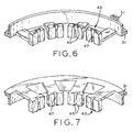
- the stator end cap 31 comprises wire retaining means 43 that receive and fixedly retain the quadrature winding 29 at the radially inner end of each tooth 37 . Because both longitudinal ends of the stator 27 have an end cap 31 and corresponding retention means, the quadrature winding 29 is held fixedly when passing through the channel 39 in the stator tooth 37 .
- the wire retention means 43 comprise nubs 45 spaced apart a distance less than the quadrature winding 29 diameter.
- the nubs 45 are sized and shaped for frictional engagement with the quadrature winding 29 .
- the nubs 45 are spaced apart a distance less than the quadrature winding 29 diameter such that an interference fit exists, holding the quadrature winding in place during automated (or manual) winding and operation of the dynamoelectric machine 21 .
- Several recesses 47 on the radially inner portion of the end cap 31 are in registration with the corresponding channels 39 on the teeth 37.
- the quadrature winding 29 runs through the recess 47 and is held in place by the nubs 45 disposed on opposite sides of the recess on the portion of the end cap 31 farthest from the stator 27 .
- the stator end cap 31 comprises polymeric material such that the nubs 45 are formed integrally with the end cap.
- the polymeric material also functions as an additional insulator between the stator 27 , the main winding 41 , and the quadrature winding 29.
Landscapes
- Engineering & Computer Science (AREA)
- Power Engineering (AREA)
- Insulation, Fastening Of Motor, Generator Windings (AREA)
- Manufacture Of Motors, Generators (AREA)
Claims (10)
- Machine dynamoélectrique (21) comprenant :un rotor (23) comportant au moins un aimant permanent, comprenant :un stator (27) comportant un noyau de stator ayant une ouverture centrale dans laquelle est placé le rotor, le noyau de stator ayant des dents (37) qui s'étendent radialement vers l'intérieur dans l'ouverture centrale, et un enroulement enroulé autour d'au moins certaines des dents (37) du noyau de stator ;un enroulement en quadrature (29) positionné de manière à produire un signal de sortie représentatif de la position angulaire du rotor, l'enroulement en quadrature (29) comportant du fil métallique qui s'étend dans le sens longitudinal du noyau de stator le long des extrémités radialement intérieures d'au moins certaines des dents de stator (37) ; etcaractérisée par:un moyen de retenue de fil (43) associé à au moins certaines des dents de stator pour accrocher et retenir de manière fixe le fil d'enroulement en quadrature pour immobiliser l'enroulement en quadrature sur le noyau de stator ;ledit moyen de retenue de fil (43) comprenant une paire d'ergots (45) séparés par une distance inférieure au diamètre du fil d'enroulement en quadrature, de sorte que le fil est logé entre les ergots (45) en ajustement avec serrage, ledit moyen de retenue de fil étant situé généralement aux extrémités radialement intérieures desdites au moins certaines dents de stator (37).
- Machine dynamoélectrique selon la revendication 1, dans laquelle ledit moyen de retenue de fil (43) est placé aux deux extrémités longitudinales du noyau de stator, et est conçu pour recevoir et retenir de manière fixe le fil de l'enroulement en quadrature (29) généralement à l'extrémité radialement intérieure desdites au moins certaines dents de stator (37).
- Machine dynamoélectrique selon la revendication 1 ou 2, dans laquelle les paires d'ergots (45) constituent des premières paires d'ergots, la machine dynamoélectrique comprenant en outre une deuxième paire d'ergots pour chacune des premières paires d'ergots, chaque deuxième paire d'ergots étant en position généralement adjacente aux extrémités radialement extérieures des dents (37) et en alignement radial avec une paire correspondante parmi les premières paires d'ergots.
- Machine dynamoélectrique selon l'une quelconque des revendications précédentes, comprenant en outre des obturateurs d'extrémité (31) en matériau polymère et ayant des dents correspondant aux dents (37) du noyau de stator, les obturateurs d'extrémité étant montés sur les extrémités respectives du noyau de stator, les ergots (45) étant formés d'un seul tenant avec les obturateurs d'extrémité.
- Machine dynamoélectrique selon l'une quelconque des revendications précédentes, dans laquelle lesdites au moins certaines dents (37) ont chacune un canal dans leurs extrémités radialement intérieures s'étendant dans le sens longitudinal du noyau de stator, les canaux recevant le fil d'enroulement en quadrature.
- Machine dynamoélectrique selon la revendication 4, dans laquelle les obturateurs d'extrémité (31) ont chacun un évidement en correspondance avec un canal correspondant de l'une desdites au moins certaines dents de stator (37), les ergots (45) étant disposés sur des côtés opposés de l'évidement.
- Obturateur d'extrémité de stator (31) pour une machine dynamoélectrique (21) conforme à l'une quelconque des revendications précédentes pour retenir un enroulement en quadrature (29) utilisé pour détecter la position angulaire d'un rotor à aimant permanent (23) situé dans un noyau de stator de la machine dynamoélectrique, l'obturateur d'extrémité de stator étant caractérisé par :une partie bague extérieure ayant un diamètre extérieur qui correspond à un diamètre extérieur du noyau de stator, un diamètre intérieur et une ouverture centrale ;des dents (37) faisant saillie depuis le diamètre intérieur de la partie bague radialement vers l'intérieur dans l'ouverture centrale de l'obturateur d'extrémité ;un moyen de retenue de fil (43) situé généralement aux extrémités radialement intérieures d'au moins certaines des dents (37) pour recevoir et retenir de manière fixe le fil d'enroulement en quadrature qui forme l'enroulement en quadrature ;ledit moyen de retenue de fil (43) comprenant une paire d'ergots (45) séparés par une distance inférieure au diamètre du fil d'enroulement en quadrature, de sorte que le fil peut être logé entre les ergots (45) en ajustement avec serrage, ledit moyen de retenue de fil (43) étant situé généralement aux extrémités radialement intérieures desdites au moins certaines dents.
- Obturateur d'extrémité de stator selon la revendication 7, dans lequel les paires d'ergots (45) constituent des premières paires d'ergots, l'obturateur d'extrémité de stator (31) comprenant en outre une deuxième paire d'ergots pour chacune des premières paires d'ergots, chaque deuxième paire d'ergots étant située généralement sur la partie bague, en position adjacente aux extrémités radialement extérieures des dents (37) et en alignement radial avec une paire correspondante parmi les premières paires d'ergots.
- Obturateur d'extrémité de stator selon la revendication 7 ou 8, dans lequel l'obturateur d'extrémité (31) est en matériau polymère et les ergots (45) sont formés d'un seul tenant avec l'obturateur d'extrémité.
- Obturateur d'extrémité de stator selon l'une quelconque des revendications 7 à 9, comprenant en outre un évidement situé à l'extrémité radialement intérieure de chacune desdites au moins certaines dents (37), les ergots (45) étant disposés sur des côtés opposés de l'évidement.
Applications Claiming Priority (2)
| Application Number | Priority Date | Filing Date | Title |
|---|---|---|---|
| US964578 | 1997-11-05 | ||
| US08/964,578 US6066905A (en) | 1997-11-05 | 1997-11-05 | Dynamoelectric machine: quadrature winding retention apparatus |
Publications (3)
| Publication Number | Publication Date |
|---|---|
| EP0915558A2 EP0915558A2 (fr) | 1999-05-12 |
| EP0915558A3 EP0915558A3 (fr) | 2002-01-02 |
| EP0915558B1 true EP0915558B1 (fr) | 2007-01-17 |
Family
ID=25508721
Family Applications (1)
| Application Number | Title | Priority Date | Filing Date |
|---|---|---|---|
| EP98309048A Expired - Lifetime EP0915558B1 (fr) | 1997-11-05 | 1998-11-05 | Fixation d'un enroulement en quadrature d'une machine dynamoélectrique |
Country Status (3)
| Country | Link |
|---|---|
| US (1) | US6066905A (fr) |
| EP (1) | EP0915558B1 (fr) |
| DE (1) | DE69836889T2 (fr) |
Cited By (1)
| Publication number | Priority date | Publication date | Assignee | Title |
|---|---|---|---|---|
| WO2025133504A1 (fr) * | 2023-12-22 | 2025-06-26 | Safran Electrical & Power | Système de propulsion d'un aéronef comprenant un dispositif d'acquisition de la vitesse de rotation du rotor du moteur électrique |
Families Citing this family (33)
| Publication number | Priority date | Publication date | Assignee | Title |
|---|---|---|---|---|
| JP3666727B2 (ja) * | 1999-07-05 | 2005-06-29 | 本田技研工業株式会社 | ハイブリッド車両駆動装置 |
| DE10005232C2 (de) * | 2000-02-05 | 2003-01-30 | Prec Motors Deutsche Minebea G | Spindelmotor für Festplatten mit höhenreduziertem Stator |
| AU2001289191A1 (en) * | 2000-09-06 | 2002-03-22 | Robert W. Ward | Stator core design |
| US7012350B2 (en) * | 2001-01-04 | 2006-03-14 | Emerson Electric Co. | Segmented stator switched reluctance machine |
| US6897591B2 (en) * | 2001-03-26 | 2005-05-24 | Emerson Electric Co. | Sensorless switched reluctance electric machine with segmented stator |
| US6744166B2 (en) * | 2001-01-04 | 2004-06-01 | Emerson Electric Co. | End cap assembly for a switched reluctance electric machine |
| US6707225B2 (en) * | 2001-02-26 | 2004-03-16 | Delco Remy International, Inc. | Radiused stator core end faces |
| US6750575B2 (en) * | 2001-08-21 | 2004-06-15 | General Electric Company | Method and apparatus for sensing the angular position of a rotating member |
| DK1437817T3 (da) * | 2003-01-10 | 2013-06-17 | Askoll Holding Srl | Synkron elmotor med permanentmagnetrotor og forbedrede støttespoler til cirkulationspumper i varme- og airconditionanlæg |
| US7414347B2 (en) * | 2004-03-23 | 2008-08-19 | Emerson Electric Co. | End cap for segmented stator |
| US7116023B2 (en) * | 2004-03-23 | 2006-10-03 | Emerson Electric Co. | End cap for interconnecting winding coils of a segmented stator to reduce phase-on-phase conditions and associated methods |
| FI117918B (fi) * | 2004-08-19 | 2007-04-13 | Abb Oy | Järjestely sähkökoneessa |
| US7646130B2 (en) * | 2006-04-26 | 2010-01-12 | Gm Global Technology Operations, Inc. | Stator segment and method of assembly |
| WO2008105054A1 (fr) * | 2007-02-26 | 2008-09-04 | Mitsubishi Electric Corporation | Stator de moteur, moteur et pompe, et procédé de fabrication de moteur |
| DE102008007402A1 (de) * | 2008-02-04 | 2009-08-06 | BSH Bosch und Siemens Hausgeräte GmbH | Permanentmagneterregte elektrische Maschine für ein Hausgerät und Schaltungsanordnung mit einer permanentmagneterregten Maschine |
| JP4535147B2 (ja) * | 2008-02-29 | 2010-09-01 | 株式会社デンソー | 回転電機の固定子及び回転電機 |
| BR112012017122B1 (pt) | 2010-01-14 | 2021-09-28 | Senvion Gmbh | Feixe compósito para uma pá de turbina eólica |
| US10137542B2 (en) | 2010-01-14 | 2018-11-27 | Senvion Gmbh | Wind turbine rotor blade components and machine for making same |
| JP4880804B2 (ja) * | 2010-02-16 | 2012-02-22 | パナソニック株式会社 | 同期電動機駆動システム |
| JP5642291B2 (ja) * | 2011-10-13 | 2014-12-17 | 三菱電機株式会社 | 回転電機 |
| JP5938903B2 (ja) * | 2011-12-28 | 2016-06-22 | 株式会社富士通ゼネラル | 電動機 |
| JP5953200B2 (ja) * | 2012-10-15 | 2016-07-20 | 山洋電気株式会社 | ブラシレスモータ用インシュレータ、ブラシレスモータ用ステータ、ブラシレスモータ、およびブラシレスモータの製造方法 |
| DE102012020329A1 (de) * | 2012-10-17 | 2014-04-17 | Sew-Eurodrive Gmbh & Co Kg | Elektromotor und Verfahren zum Herstellen eines Elektromotors |
| KR20150049036A (ko) * | 2013-10-29 | 2015-05-08 | 삼성전자주식회사 | 모터 및 스테이터 코일의 권선방법 |
| GB2553839A (en) * | 2016-09-16 | 2018-03-21 | Johnson Electric Sa | Electric motor |
| FR3058282B1 (fr) * | 2016-11-03 | 2018-10-26 | Valeo Equipements Electriques Moteur | Stator de machine electrique tournante muni de bobines a enroulement controle |
| JP2020202705A (ja) * | 2019-06-12 | 2020-12-17 | 本田技研工業株式会社 | 回転電機 |
| DE102020211671A1 (de) * | 2020-09-17 | 2022-03-17 | BSH Hausgeräte GmbH | Wäschepflegegerät mit einem elektrischen Synchronmotor |
| TWI778515B (zh) * | 2021-02-05 | 2022-09-21 | 姚立和 | 結線架、馬達定子及應用彼之馬達 |
| US11632021B2 (en) * | 2021-04-05 | 2023-04-18 | Raytheon Company | Dynamo-electric machine |
| CN114157097B (zh) * | 2021-11-18 | 2023-09-26 | 东南大学 | 磁悬浮磁通切换电机的定子结构 |
| EP4187758B1 (fr) * | 2021-11-29 | 2026-04-29 | Hamilton Sundstrand Corporation | Stator pour machines électriques |
| EP4674030A1 (fr) * | 2023-03-02 | 2026-01-07 | H3X Technologies Inc. | Capuchon thermique pour enroulement de stator |
Family Cites Families (9)
| Publication number | Priority date | Publication date | Assignee | Title |
|---|---|---|---|---|
| US2894157A (en) * | 1956-07-20 | 1959-07-07 | Wayne J Morrill | Winding forms for dynamoelectric machines |
| US3780323A (en) * | 1971-09-15 | 1973-12-18 | Gen Electric | Insulatingly covered dynamoelectric machine |
| DE2901676A1 (de) * | 1979-01-17 | 1980-08-14 | Papst Motoren Kg | Kollektorloser gleichstrommotor |
| US4340829A (en) * | 1979-06-22 | 1982-07-20 | Sheller Globe Corporation | Molded end coil insulator |
| US4386288A (en) * | 1981-05-26 | 1983-05-31 | The Superior Electric Company | Stepping motors having detented winding and winding method |
| JPH053454A (ja) * | 1991-06-25 | 1993-01-08 | Matsushita Electric Works Ltd | 光ワイヤレス受信器 |
| JP3153287B2 (ja) * | 1991-10-02 | 2001-04-03 | アスモ株式会社 | ブラシレスモータ |
| JP3315428B2 (ja) * | 1992-04-01 | 2002-08-19 | 株式会社荏原製作所 | 磁気軸受装置 |
| US5796194A (en) * | 1996-07-15 | 1998-08-18 | General Electric Company | Quadrature axis winding for sensorless rotor angular position control of single phase permanent magnet motor |
-
1997
- 1997-11-05 US US08/964,578 patent/US6066905A/en not_active Expired - Lifetime
-
1998
- 1998-11-05 DE DE69836889T patent/DE69836889T2/de not_active Expired - Lifetime
- 1998-11-05 EP EP98309048A patent/EP0915558B1/fr not_active Expired - Lifetime
Cited By (2)
| Publication number | Priority date | Publication date | Assignee | Title |
|---|---|---|---|---|
| WO2025133504A1 (fr) * | 2023-12-22 | 2025-06-26 | Safran Electrical & Power | Système de propulsion d'un aéronef comprenant un dispositif d'acquisition de la vitesse de rotation du rotor du moteur électrique |
| FR3157355A1 (fr) * | 2023-12-22 | 2025-06-27 | Safran Electrical & Power | Système de propulsion d’un aéronef comprenant un dispositif d’acquisition de la vitesse de rotation du rotor du moteur électrique |
Also Published As
| Publication number | Publication date |
|---|---|
| DE69836889T2 (de) | 2007-10-18 |
| DE69836889D1 (de) | 2007-03-08 |
| US6066905A (en) | 2000-05-23 |
| EP0915558A3 (fr) | 2002-01-02 |
| EP0915558A2 (fr) | 1999-05-12 |
Similar Documents
| Publication | Publication Date | Title |
|---|---|---|
| US6066905A (en) | Dynamoelectric machine: quadrature winding retention apparatus | |
| KR102215005B1 (ko) | Bldc 모터 | |
| CA2147653C (fr) | Appareil dynamo-electrique discoide | |
| KR100565220B1 (ko) | 자기저항 동기 전동기 | |
| US20090009114A1 (en) | Synchronous machine | |
| CN107306065B (zh) | 最小化由测量元件维持的电磁干扰的旋转电机 | |
| EP3780347B1 (fr) | Moteur et moteur d'essuie-glace sans balais | |
| US6710480B1 (en) | Rotation angle measuring device with magnetized commutator | |
| EP0431749A1 (fr) | Capteur de rotation à variation de réluctance | |
| US6750575B2 (en) | Method and apparatus for sensing the angular position of a rotating member | |
| JP4088847B2 (ja) | ブラシレスモータの固定子巻線 | |
| EP4742516A1 (fr) | Moteur à courant continu doté d'une bobine d'enroulement d'induit multiphase câblée à un stator de manière indépendante et parallèle, rotor doté d'aimants permanents multiples, et bobine enroulée en parallèle selon un pôle de rotor | |
| JP3798677B2 (ja) | ブラシレスモータ | |
| KR100677242B1 (ko) | 비엘디시 모터의 회전자 위치감지장치 | |
| JPH0787687B2 (ja) | ブラシレスモータ | |
| JP6588830B2 (ja) | 回転電機 | |
| KR101287357B1 (ko) | 모터 | |
| WO2006049995A2 (fr) | Moteur a repulsion a couple eleve | |
| JPS63190544A (ja) | アウタ−ロ−タ型dcブラシレスモ−タ | |
| KR100321878B1 (ko) | 자석 가동형 브러시 없는 모터 | |
| JPS63190543A (ja) | インナ−ロ−タ型dcブラシレスモ−タ | |
| KR101724098B1 (ko) | 일체형 비접촉식 모터 및 브러시와 정류자를 이용한 인버터 유닛 | |
| KR19990057091A (ko) | 브러시리스 모터의 회전자 구조 | |
| KR200265987Y1 (ko) | 인덕션 교류 서보모터의 구조 | |
| KR100565221B1 (ko) | 회전 마그네트 타입 단상 유도 전동기 |
Legal Events
| Date | Code | Title | Description |
|---|---|---|---|
| PUAI | Public reference made under article 153(3) epc to a published international application that has entered the european phase |
Free format text: ORIGINAL CODE: 0009012 |
|
| AK | Designated contracting states |
Kind code of ref document: A2 Designated state(s): AT BE CH CY DE DK ES FI FR GB GR IE IT LI LU MC NL PT SE Kind code of ref document: A2 Designated state(s): DE IT |
|
| AX | Request for extension of the european patent |
Free format text: AL;LT;LV;MK;RO;SI |
|
| PUAL | Search report despatched |
Free format text: ORIGINAL CODE: 0009013 |
|
| AK | Designated contracting states |
Kind code of ref document: A3 Designated state(s): AT BE CH CY DE DK ES FI FR GB GR IE IT LI LU MC NL PT SE |
|
| AX | Request for extension of the european patent |
Free format text: AL;LT;LV;MK;RO;SI |
|
| RIC1 | Information provided on ipc code assigned before grant |
Free format text: 7H 02K 29/12 A, 7H 02K 3/20 B |
|
| 17P | Request for examination filed |
Effective date: 20020702 |
|
| AKX | Designation fees paid |
Free format text: DE IT |
|
| GRAP | Despatch of communication of intention to grant a patent |
Free format text: ORIGINAL CODE: EPIDOSNIGR1 |
|
| GRAS | Grant fee paid |
Free format text: ORIGINAL CODE: EPIDOSNIGR3 |
|
| GRAA | (expected) grant |
Free format text: ORIGINAL CODE: 0009210 |
|
| AK | Designated contracting states |
Kind code of ref document: B1 Designated state(s): DE IT |
|
| REF | Corresponds to: |
Ref document number: 69836889 Country of ref document: DE Date of ref document: 20070308 Kind code of ref document: P |
|
| PLBE | No opposition filed within time limit |
Free format text: ORIGINAL CODE: 0009261 |
|
| STAA | Information on the status of an ep patent application or granted ep patent |
Free format text: STATUS: NO OPPOSITION FILED WITHIN TIME LIMIT |
|
| 26N | No opposition filed |
Effective date: 20071018 |
|
| PGFP | Annual fee paid to national office [announced via postgrant information from national office to epo] |
Ref country code: DE Payment date: 20131127 Year of fee payment: 16 |
|
| PGFP | Annual fee paid to national office [announced via postgrant information from national office to epo] |
Ref country code: IT Payment date: 20131126 Year of fee payment: 16 |
|
| REG | Reference to a national code |
Ref country code: DE Ref legal event code: R119 Ref document number: 69836889 Country of ref document: DE |
|
| PG25 | Lapsed in a contracting state [announced via postgrant information from national office to epo] |
Ref country code: DE Free format text: LAPSE BECAUSE OF NON-PAYMENT OF DUE FEES Effective date: 20150602 |
|
| PG25 | Lapsed in a contracting state [announced via postgrant information from national office to epo] |
Ref country code: IT Free format text: LAPSE BECAUSE OF NON-PAYMENT OF DUE FEES Effective date: 20141105 |