EP0915737B1 - Dispositif collecteur - Google Patents
Dispositif collecteur Download PDFInfo
- Publication number
- EP0915737B1 EP0915737B1 EP97932645A EP97932645A EP0915737B1 EP 0915737 B1 EP0915737 B1 EP 0915737B1 EP 97932645 A EP97932645 A EP 97932645A EP 97932645 A EP97932645 A EP 97932645A EP 0915737 B1 EP0915737 B1 EP 0915737B1
- Authority
- EP
- European Patent Office
- Prior art keywords
- collector device
- sealing
- support body
- receiving container
- retaining
- Prior art date
- Legal status (The legal status is an assumption and is not a legal conclusion. Google has not performed a legal analysis and makes no representation as to the accuracy of the status listed.)
- Expired - Lifetime
Links
Images



Classifications
-
- B—PERFORMING OPERATIONS; TRANSPORTING
- B01—PHYSICAL OR CHEMICAL PROCESSES OR APPARATUS IN GENERAL
- B01L—CHEMICAL OR PHYSICAL LABORATORY APPARATUS FOR GENERAL USE
- B01L3/00—Containers or dishes for laboratory use, e.g. laboratory glassware; Droppers
- B01L3/50—Containers for the purpose of retaining a material to be analysed, e.g. test tubes
- B01L3/508—Rigid containers without fluid transport within
- B01L3/5082—Test tubes per se
- B01L3/50825—Closing or opening means, corks, bungs
-
- B—PERFORMING OPERATIONS; TRANSPORTING
- B01—PHYSICAL OR CHEMICAL PROCESSES OR APPARATUS IN GENERAL
- B01L—CHEMICAL OR PHYSICAL LABORATORY APPARATUS FOR GENERAL USE
- B01L3/00—Containers or dishes for laboratory use, e.g. laboratory glassware; Droppers
- B01L3/50—Containers for the purpose of retaining a material to be analysed, e.g. test tubes
- B01L3/502—Containers for the purpose of retaining a material to be analysed, e.g. test tubes with fluid transport, e.g. in multi-compartment structures
- B01L3/5021—Test tubes specially adapted for centrifugation purposes
- B01L3/50215—Test tubes specially adapted for centrifugation purposes using a float to separate phases
-
- Y—GENERAL TAGGING OF NEW TECHNOLOGICAL DEVELOPMENTS; GENERAL TAGGING OF CROSS-SECTIONAL TECHNOLOGIES SPANNING OVER SEVERAL SECTIONS OF THE IPC; TECHNICAL SUBJECTS COVERED BY FORMER USPC CROSS-REFERENCE ART COLLECTIONS [XRACs] AND DIGESTS
- Y10—TECHNICAL SUBJECTS COVERED BY FORMER USPC
- Y10S—TECHNICAL SUBJECTS COVERED BY FORMER USPC CROSS-REFERENCE ART COLLECTIONS [XRACs] AND DIGESTS
- Y10S220/00—Receptacles
- Y10S220/916—Container including axially opposed removable closures
Definitions
- the invention relates to a receiving device according to the preamble of claim 1.
- US 4,342,724 A is a receiving device with a receiving container as well Both open end regions arranged closable locking devices as needed known.
- the receptacle has a container wall with inner and outer-surface-on, which bounds an interior.
- the two open formed end areas can each be closed by sealing bodies of the closure devices, the wall parts interacting with the sealants each being cylindrical are trained.
- the sealing in the end area shown below is done by the Interaction of the sealing washer resting on the front end of the receptacle with the Holding cap that presses the sealing washer onto the front end of the receptacle.
- the Insert part points in the direction of the cylindrical inner surface Centering flanges spaced apart from one another along the longitudinal central axis, with displacement of the Insert part in the direction of the longitudinal axis through a cooperating with the receptacle Holding approach is prevented.
- the insert part in the area of Longitudinal central axis on an opening completely penetrating this, which between the two ends of the same.
- the further end region of the receptacle points a smaller cross-sectional dimension compared to the wider interior.
- WO 93/22647 A1 describes a method and an apparatus for separating a mixture of at least two media, in which the receptacle through an approximately cylindrical or tubular housing with a container wall is formed, which delimits an interior and the receptacle two in End regions spaced apart from one another in the direction of its longitudinal central axis, each with open ones Has end faces.
- closable opening devices if necessary closable, one of which the receptacle on its outer Surface overlaps and the other closure device is designed such that this comprises a pierceable sealing body and a holding element for the sealing body, wherein the sealing body is inserted into the interior of the receptacle and the holding element engages over the receptacle in the area of its outer surface.
- a separator is used, which by a Base body is formed with sealing lips protruding therefrom.
- a receptacle for centrifuging has become known from US 3,434,615 A, which is formed by a container body open on one side, which one neck-like approach, with an inner surface of the neck-like approach tapering is formed in the direction of the interior.
- a conical sealing device in the form of a sealing plug can be used with sealing rings arranged on the circumference, with the sealing plug on the side facing away from the interior of the housing from a flange of a cap in Reference to the housing is kept.
- Another blood collection device has become known from US Pat. No. 3,897,343 A, the separating device already in the area before the introduction of the media to be separated the closed end of the receptacle is arranged.
- a pierceable closure device is arranged at the front end of the receptacle, which for introducing the medium into the interior of the receiving device from a Pierce the needle and then insert the medium into the interior becomes.
- the separation device is located below before the separation process begins of the medium to be separated and only floats after the centrifugal force has been applied of the chosen specific weight on the separated and heavier components of the medium and takes up only after the centrifugal force has been applied a sealing position between the two separate components of the medium on.
- the device is that the separation device with both before the start of the separation process Components of the medium come into contact and it is possible that partial quantities the heavier medium in the area above the sealing device on the separating device stick and thus subsequently mixing or contaminating the Lighter medium located above the separation device after the separation process has ended is possible.
- a receiving device for a mixture of at least two media which has a test tube-like receiving container which is closed in an open end region with a closure device and in which a separating device for separating the different media of the mixture the separation is used.
- the separating device is provided in the central region with a through-opening through which the mixture enters the remaining interior of the receptacle can be introduced.
- a height corresponding to the usual remaining amount of the other medium is in the direction of the closed one End provided conically widening end stop, with which the separating device runs on the end stop, which penetrates through the opening.
- receptacles for centrifuging mixtures to be separated from at least two different media in which the receptacle in both frontal areas is closed with a closure device are known from WO 96/05770 A1.
- a separating device formed by a sealing washer which is formed by a gel.
- this gel flask migrates due to its specific weight, which is higher than the specific weight of the medium with the lower specific weight and lower than the specific weight the medium with a higher specific weight, due to the centrifugal forces acting on it between the two different, separate media. Positioned in this Position can thus separate one medium from the other medium Mixture take place.
- the disadvantage here is that the storage period, due to the separating device made of gel, in many cases not sufficient for the normal duration of use.
- the present invention has for its object to provide a recording device Separation of several media to create a mixture, which quickly to different Mixtures are adaptable and a long storage period and high operational reliability too when used by inexperienced personnel.
- the object of the invention is achieved by the design of the receiving device according to the Characteristic part of claim 1 solved. Due to the design of the receptacle in connection with the two closure devices in the region of the two end regions simple filling of the interior of the receptacle is made possible. This configuration enables a reinforced floor area, which also if such a receptacle is accidentally dropped, bursting prevented with high security. In addition, this receptacle is relatively simple designed injection molding tools easily and also in tools with multiple nests can be produced inexpensively. Furthermore, this reinforced area can simultaneously be used to securely anchor the holding element.
- Adequate pretensioning of the sealing body in the opening can be achieved through further training can be achieved according to claims 15 and 16.
- a good installation of the sealing body and a drip from the outlet can be achieved through further training be avoided according to claim 18.
- Adequate tightness can also be achieved by developing the sealing body according to claim 19 can be achieved because it also uses materials that meet the high Centrifugal forces have sufficient dimensional stability to ensure tightness.
- the embodiment according to claim 26 allows a roll-off protection in a simple manner prevents the receptacle, if it has a cylindrical outer shape, can roll away.
- a sufficient prestressing force of the sealing body in the receptacle can be obtained from the claims 30 and 31 can be achieved, with the latter embodiment despite a good Support of the sealing body, the accessibility to the interior of the receptacle is ensured remains.
- the receiving device can also advantageously be used in conjunction with a separating device be used according to claim 32, because by dividing them into a sealing element and a support body, the two parts are each optimally configured according to their function can be. Due to the use of its own support body is due to the density and the specific weight related to the different applications easily adjustable. In addition there is a good seal after separation between the separate media is achieved, which also requires longer storage allows. Furthermore, a full seal over the entire circumference and thus one flawless separation can be ensured even under different pressure conditions.
- the separating device can be selected by the choice of material for the sealing element matched to the various components of the mixture to be separated and so on the one hand a perfect separation during the centrifugation process and on the other hand after the same a secure seal between the separate components of the mixture can be achieved.
- the training variant according to claim 49 enables production in a simple manner a passage gap for one of the two media during the centrifugation process.
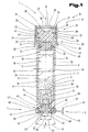
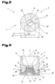
- FIG. 1 and 2 show a receiving device 1 for a mixture 2 of at least two mutually different constituents or media 3, 4, such as body fluids, tissue parts or tissue dressings, which is designed in such a way that that in the receiving device 1 Mixture 2 is separable in at least two of its components.
- This separation or separation of the mixture 2 into its constituents or media 3, 4 can, for example, be carried out physically by centrifugation in a conventional manner and starting from the rest position until a radial centrifugal force (rcf) of 1,000 g to 5,000 g, preferably 2,200 g can be carried out, g being the force of gravity and 1 g being 9.81 m / s 2 .
- rcf radial centrifugal force
- the receiving device 1 consists of an approximately cylindrical one Receptacle 5 with arranged at both end portions 6, 7 spaced from each other Closure devices 8, 9 and one into one of the receptacle 5 enclosed interior 10 used separator 11.
- This receptacle 5 can, for example, also be designed as an evacuated blood sampling tube or be used.
- the receptacle 5 can be bottle-shaped, vial-shaped or piston-shaped, for example Like. As well as made of different materials, such as Plastic or glass. Used as a material for the receptacle Chosen plastic, this can be liquid-tight, in particular waterproof and optionally be gastight and, for example, as polypropylene (PP), polyethylene (PE), high-density polyethylene (PE-HD), acrylonitrite-butadiene-styrene copolymers (ABS) or the like. Or a combination thereof. Furthermore, the receptacle points 5 a container wall 12 with a wall thickness 13, the container wall 12, starting from one end region 6 with approximately the same internal dimension 14 extends to the further end region 7.
- PP polypropylene
- PE polyethylene
- PE-HD high-density polyethylene
- ABS acrylonitrite-butadiene-styrene copolymers
- the container wall 12 of the receptacle 5 has an inner surface 15 facing the interior 10 and an outer surface 16 facing away from it, which thus has an outer circumference 17 sets for the receptacle 5. Due to the inner surface 15 of the container wall 12 with the inner clear dimension 14 is thus an inner cross section 18, which has a wide variety of cross-sectional shapes, e.g. circular, elliptical, oval, polygonal, etc., may have set. Due to the inner Dimension 14 plus twice the wall thickness 13 of the receptacle 5 forms an outer dimension 19 with an outer cross section 20.
- the shape of the outer cross section 20 can in turn be circular, elliptical, oval, be polygonal, etc., but it is also possible to shape the outer Cross-section 20 to be different from the shape of the inner cross-section 18.
- the inner dimension 14 and the outer dimension 19 of the receptacle 5, starting from an end region 6 to that of this distanced further end region 7 preferably decreases minimally in terms of shape is formed, for example, the receptacle 5 when it is off Plastic material is manufactured in an injection molding process from the injection mold easy to demould. Centric to the inner dimension 14 or the inner cross section 18, the receptacle 5 points out from the end region 6 to the end region 7 extending longitudinal central axis 21.
- the end region 6 has an open one Front side 22, which can be closed by the closure device 8, which can be opened as required is.
- the closure device 8 consists of an open end face 22 comprehensive cap 23 and a sealing device 24 held therein, such for example a sealing plug 25 made of a pierceable, highly elastic and self-sealing material, such as Pharmaceutical rubber, silicone rubber or Bromobutyl.
- This cap 23 is arranged concentrically with the longitudinal central axis 21 and formed by an annular cap jacket 26.
- the sealing device 24 is in the present exemplary embodiment formed by the sealing plug 25 and has a circumferential and in cylindrical sealing surface arranged approximately concentrically to the longitudinal center axis 21 36, which in its sealing position in the section of the end region 6 on the inner Surface 15 of the receptacle 5 comes to rest.
- the sealing device 24 has an approximately aligned on the longitudinal center axis 21, further sealing surface 37, which in cooperation with the sealing surface 36 abutting the inner surface 15 the interior 10 of the receptacle 5 on its open end face 22 opposite seals off or seals off the external environment.
- the sealing device 24 can preferably be on the retaining ring 34 facing side have a recess 38 which has approximately the same cross-sectional area has an opening 39, this opening 39 being of such dimensions is formed that an unhindered passage and subsequent piercing through the sealing device 24 is possible.
- the diameter of the opening 39 of the retaining ring 34 smaller than a largest outer dimension of the extension 35 in a plane perpendicular to the longitudinal central axis 21.
- this outer dimension of the sealing device 24 is so dimensioned that this at least twice the wall thickness 13 of the receptacle 5 is larger than the inner dimension 14 of the inner cross section 18 and thus the interior 10.
- the tightness of the closure device 8 for the open end face 22 the receiving device 1 is further improved if an outer diameter the sealing device 24 in the area of its sealing surface 36 in the relaxed state outside of the receptacle 5 is larger than the inner dimension 14 of the receptacle 5th
- cap jacket 26 as a truncated cylinder jacket or truncated cone jacket is formed, whereby an overlap of the cap jacket 26 is guaranteed in the area of the upper end face 22.
- These guide extensions 40, 41 act on the inside of the cap jacket 26 arranged guide webs 42, 43 together, whereby it is made possible that when the cap 23 is pushed open in the direction of the longitudinal central axis 21 of the receptacle 5 in the direction of the open end face 22 of the same and a corresponding clockwise rotation of the guide webs 42, 43 run on the guide extensions 40, 41 and that due to the combined Rotational and longitudinal movement due to the guidance of the guide webs 42, 43 along the Guide extensions 40, 41, the sealing device 24 with its sealing surface 36 in the Interior 10 of the receptacle can be inserted or inserted.
- the receiving device has 1 at the end region 7 facing away from the end region 6
- Closure device 9 which consists of a pierceable sealing body 44 a pierceable, highly elastic and self-sealing material, in particular a rubber, pharmaceutical rubber, silicone rubber or bromobutyl rubber and a holding element 45 for holding the sealing body 44 on the receptacle 5 is formed is.
- the holding element 45 has means for coupling, such as, for example one or more coupling parts 46 of a coupling device 47 between the Holding element 45 and the receptacle 5 and on the other hand means for holding, such as one or more holding parts 48 of a holding device 49, the Sealing body 44 in a sealing position in a tapering towards the interior, opposite to the sealing body 44 formed opening 50.
- the Form surface of the opening 50 in its surface quality as a sealing surface.
- the sealing body 44 is conical, in particular as a truncated cone with a cone angle 51 and has an end face 52 facing the holding element 45 with a diameter 53 and one facing away from it, the interior 10 of the receptacle 5 further front end 54 with a smaller diameter 53 Diameter 55 on.
- the receptacle 5 has the previously described, opposite to the cone angle 51 of the sealing body 44 formed opening 50 in its end region 7, in which the sealing body 44 for closing or sealing the interior 10 opposite the external atmosphere can be used and by means of the holding element 45 in this sealing position is held securely.
- the opening 50 faces the interior 10 opposite side of the receptacle 5 a diameter 56 and a diameter 57 in the area of the interior 10.
- the is preferred Diameter 55 of the front end 54 of the sealing body 44 is larger than the smallest diameter 57 of the opening 50 receiving the sealing body 44.
- the largest Diameter 53 of the sealing body 44 larger than the largest diameter 56 also the opening 50 receiving the sealing body 44.
- This sealing contact of the sealing body 44, in particular the sealing surface 61 in the Opening 50 effect the holding means of the holding element already described above 45, which so far from the outside in a central central region of the holding element 45 protrude that these are the largest when placed on the receptacle 5 layer Diameter 53 of the sealing body 44 in the direction of the central region, ie in the direction protrude from the longitudinal central axis 21 in the radial direction.
- the holding device can 49 from individual holding parts 48 distributed over the circumference and / or by one End wall 62 of the holding element 45 with one arranged in the central region thereof Opening 63 may be formed.
- This opening 63 has an opening width 64 which is at least smaller than the largest diameter 53 of the sealing body 44. This is a secure mounting of the sealing body 44 with respect to the receptacle 5 in the latter used position guaranteed safely.
- the holding element 45 is designed like a cap and has the previously described means for coupling to the receptacle 5 on.
- the coupling parts 46 forming these can for example be formed by holding, locking or snap arms, which in the radial direction of the holding element 45 are elastically resettable, deformable.
- the coupling parts 46 of the coupling device 47 at the position of the receptacle 5 on the outer dimension 19 or over the outer circumference 17 of the receptacle 5 in the direction of its longitudinal central axis 21 protrude.
- a maximum outer dimension 65 of the holding element 45 the same and / or slightly larger than the maximum outer dimension 19 of maximum outer cross section 20 of the receptacle 5. This ensures that the outer dimension 19 of the receiving device 1 in the end region 7 despite the arrangement of the closure device 9, no or only a slight enlargement of the outer dimension 65.
- the receptacle 5 has in it End region 7 has a groove 66 which is approximately opposite to coupling part 46, which, for example, all around the entire outer circumference 17 and / or through Groove parts 67 distributed over the circumference are formed in segments.
- the arrangement and Formation of the groove 66 or the individual groove parts 67 or recesses, depressions etc. depend on the design of the holding element 45. But it is independent of which also possible that the coupling device 47 by over the circumference distributed arranged, preferably conically tapering receiving bores is formed, which with individual counter-trained, cone-like Interacting coupling parts 46 on the holding element 45.
- the coupling device 47 between the holding element 45 and the receptacle 5 in such a way that, for example, on the receptacle 5 above
- the outer circumferential projecting coupling parts are arranged, which have a groove-shaped Arrangement or groove parts of the holding element 45 cooperate. This is likewise again the formation of the coupling device 47 between the holding element 45 and the receptacle 5 guaranteed.
- the receptacle has 5 in its end region 7, in which the opening 50 for inserting the sealing body 44 or for filling or filling the interior 10, one opposite the wall thickness 13 of the container wall 12 greater wall thickness, which in this end region 7 the formation of the opening 50 or the coupling device 47 can be done. Furthermore, it is advantageous if the coupling device 47 on Outer periphery 17 of the receptacle 5 in a position covering the opening 50 is arranged, which results in a strength-favorable design of the end region 7, due to the greater wall thickness in this section, can be achieved.
- the separating device 11 is shown in the interior 10 of the receptacle 5.
- a sealing device 68 in the present exemplary embodiment a sealing element 69 made of a first material and a support body 70 made of a second, different material is formed.
- the sealing element 69 of the Sealing device 68 is preferably annular in a side wall 71 of the supporting body 70 arranged recess 72 arranged and projects beyond the side wall 71 of the support body 70, preferably circumferentially over its circumferential direction.
- the material for the sealing element 69 is resiliently deformable is and e.g. through a silicone rubber, pharmaceutical rubber, bromobutyl rubber, Rubber, a gel or an elastomeric plastic is formed.
- sealing element 69 can handle a wide variety of materials or cross-sectional shapes are used, e.g. an O-ring or flange ring or a circumferential one Sealing lip, a thin-walled web or a thin-walled lamella as a sealing element 69, e.g. can be used in grooves and / or clamping areas or the like. It is but also possible, the sealing element 69 via a molding process on the support body 70 to fix.
- the second material of the support body 70 is liquid-tight is and a higher density and / or hardness than the first material of the sealing element 69 and, if appropriate, with additives or fillers provided plastic, e.g. a thermoset, a crystal clear polystyrene and the like is.
- the support body 70 should have a gas permeability that the Gas penetration almost prevented at least in a period of 72 hours. It can also prove to be advantageous if the total weight of the support body 70 and / or the separating device 11 can be changed, for example is possible, the separating device 11 and / or the support body 70 to different Media 3, 4 of the mixture 2 to be separated exactly match. It is also advantageous if the gas permeability of the sealing element 69 is at least equal to or greater than that of the support body 70.
- the separating device 11 consists of at least one sealing element 69 made of a first material and the support body 70 made of a different second material.
- the specific weight or the density of the second material of the support body must on the one hand be smaller than the higher specific weight or the density of one of the separators 11 to be separated medium 3, 4 and on the other hand be greater than the lighter specific weight or the density of one of the medium 3, 4 to be separated by the separating device. It has proven to be advantageous if, for example, the density of the support body 70 is between 1. 03 g / cm 3 and 1.06 g / cm 3 , preferably 1.05 g / cm 3 .
- a coating 73 is, for example, the sliding movement of the separator 11 during to support the separation process and / or a chemical and / or physical Influencing the mixture 2 or the like.
- the support body 70 on one of the closure devices 8, 9 can at least the between the separating device 11 and the opposite end region 6, 7 Surface 15 may be provided with this coating 73, which for example designed to be detachable or detachable from the surface 15 on contact with the mixture 2 is and e.g. used simultaneously to fix the separating device 11 become.
- FIG. 3 is a partial area of the receiving device 1 on an enlarged scale shown, the same reference numerals as in FIGS. 1 and 2 being used for the same parts become.
- This embodiment of the closure device 9 shown here, consisting from the holding element 45 and the pierceable sealing body 44 differs from the previously described embodiments, these being different Embodiments of course form independent solutions as well as with other described embodiments in other figures can be combined.
- the end region 7 of the receptacle 5 in turn has a conical direction of the interior 10 has a tapering opening 50 into which the sealing body 44 is used for the sealing position in the same.
- the sealing body 44 by a multi-layer component from each other in particular different materials, such as from layers 74 to 76, is formed.
- the two can be spaced apart Layers 74, 76 of a softer and more suitable material for the seal and the layer 75 can be formed from a material which is harder for this purpose, for example serve as a base course.
- the one facing the holding element 45 Front end 52 of the sealing body 44 with a concave shown in simplified form Recess 77 is formed or arranged in this.
- the end face 52 of the sealing body opposite the end face 52 44 be completely concave.
- the depression 77 or the completely concave front end 54 can be Piercing thickness of the sealing body 44 to different circumstances, such as adjust a needle diameter.
- the holding element 45 is in turn cap-shaped and has in its Sealing body 44 facing end wall 62 in turn the opening described above 63 to ensure puncturing through the sealing body 44.
- the holding device 49 between the holding element 45 and the sealing body 44 can according to one of the described embodiments.
- This collar 78 can for example form part of the coupling device 47, in particular a coupling part 46 and expandable and elastic due to the selected material of the holding element 45 be resettable. In its end region facing away from the end wall 62 of the federal government 78, this can be done with at least a part of the federal government 78, collar-like coupling element 79 projecting inwards in the circumferential direction be equipped.
- the coupling element 79 as well as to arrange the collar 78 continuously on the holding element 45, so the coupling force between the receptacle 5 and the holding element 45 and in consequently, the sealing force between the sealing body 44 and the opening 50 of the To control receptacle 5.
- the coupling element 79 of the coupling device 47 can in turn engage in the previously described groove 66 of the receptacle 5, the groove 66, as already described above, again running all the way round or can optionally be arranged only in certain areas.
- the sealing body 44 attached to the holding element 45 glued or by a molding process or by a two-component injection molding is produced or connected to this.
- the Sealing body 44 and the holding element 45 made of one component, that is to say in one piece be and preferably from a highly elastic and self-sealing material, in particular from a rubber, pharmaceutical rubber, silicone rubber or bromobutyl rubber consist.
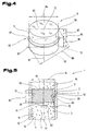
- FIG. 4 shows the separating device 11 in an enlarged, diagrammatically simplified illustration shown how this has already been described in FIG. 1, wherein for same parts same reference numerals are used.
- the separating device 11 consists of the sealing device arranged on the support body 70 68, which in this embodiment is again formed by the sealing element 69 is.
- the sealing element 69 is arranged in the region of the peripheral side wall 71 and protrudes above it on a central longitudinal axis 81 of the support body 70 opposite direction.
- the support body 70 preferably points perpendicular to the End faces 82, 83 aligned and spaced apart from one another along the longitudinal center axis 81 on which, in cooperation with the side wall 71, the support body 70 in its Define the room shape.
- the support body 70 has an in Round cross-sectional shape seen in the direction of the central longitudinal axis 81 with an outer dimension 84 on.
- the two end faces 82, 83 are Seen in the direction of the central longitudinal axis 81, spaced apart from one another at an overall height 85 arranged, the recess 72 for the sealing element 69 in its middle preferably centrally to the overall height 85, ie at distances 86, 87 from the two end faces 82, 83. is arranged.
- the distances 86, 87 different from each other to offset the recess 72 and thus the sealing element 69 in the direction of the central longitudinal axis 81. whereby the center of gravity of the separator 11 with respect to the arrangement of the sealing element 69 on the support body 70 is changeable. This can vary depending on the application the chosen physical separation type.
- the support body 70 with its Sealing elements 69 all have possible cross sections for the use of the same can, this cross section the cross section of the inner surface 15 of the Receiving device 1 must correspond to achieve the desired application.
- a diagonal corner dimension 88 for the support body 70 which must in any case be larger than the inner dimension 14 or as the inner cross section 18 of the receptacle 5 to tilt the support body 70 to avoid secured a transverse plane to the central longitudinal axis 81. This is before especially during and after the physical separation process of the two media 3, 4 of the Mixtures 2 of great importance, since otherwise the media 3, which are separated from one another, 4 of the mixture 2 after the completion of the separation process not by the separation device 11 are separated from each other in a sealed manner.
- This corner dimension 88 is determined between an intersection 89 of the lower one here End face 82 with the side wall 71 and the intersection 89 diametrically opposite intersection 90 between the lower end face 82 opposite end face 83 and which is preferably centered on the central longitudinal axis 81 aligned side wall 71.
- the side wall 71 is parallel to the overall height 85 aligned, the in the region of the peripheral side edges of the side wall 71 two end faces 82, 83 each aligned perpendicular to the height 85 Level are arranged.
- This diagonal corner dimension 88 in the case of, for example, a round support body 70 can be deduced from the root of the sum of the Pythagorean theorem Squares of the outer dimension 84 and of the height 85 running perpendicular to it determine or calculate.
- This diagonal corner dimension 88 must in any case be larger than the inner dimension 14 in the perpendicular to the longitudinal central axis 81 aligned inner cross section 18 of the separating device 11 accommodating Interior 10 of the receptacle 5.
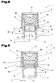
- FIG. 5 is a partial area of the receiving device 1 with that in the receiving container 5 arranged separator 11 on a larger scale during the physical Separation process of the mixture 2 from the media 3, 4 shown, being the same Parts the same reference numerals as in Figs. 1 to 4 are used.
- the separating device 11 consisting of the support body 70 and the sealing device 68 arranged thereon with sealing element 69, that described above Embodiment.
- the receptacle 5 has the inner dimension perpendicular to its longitudinal central axis 21 14, the separating device due to the centrifugal forces that occur 11 with the sealing element 69 arranged thereon against the inner surface 15 is pressed. Furthermore occurs due to the different previously described Materials of the support body 70 to the sealing element 69 only a deformation of the sealing element 69 on, as is also indicated schematically. It is in the left part of the separating device 11 of the support body 70 in its rest position dashed lines shown.
- the centrifugal force causes an offset of the central longitudinal axis 81 of the support body 70 with respect to the longitudinal central axis 21 of the receptacle 5 by a maximum deformation path 91, whereby in the opposite area the separating device 11, the sealing element 69 with respect to the inner surface 15 loses its sealing system in some areas and there is a gap in this area 92 with a width 93 in the direction measured perpendicular to the longitudinal central axis 21 forms. This is formed between the sealing element 69 and the inner surface 15 Gap 92 serves this purpose.
- the sealing element 69 takes centrifugal forces because of its resiliently resettable Properties in turn are an all-round sealing system on the inner surface 15 of the receptacle 5, but between the two media 3, 4.
- the maximum deformation path 91 of the sealing device 68, in particular of the sealing element 69 in perpendicular to the central longitudinal axis 81 of the sealing element 69 extending direction in the area projecting beyond the supporting body 11 is greater than a dimensional difference of the sealing element 69 in relation to the longitudinal central axis 21 vertical direction in a relaxed rest position and in the interior 10 of the Receiving container 5 inserted, pre-stressed position.
- FIG. 6 shows a further possible embodiment which may be independent in itself of the holding element 45 shown in view and on an enlarged scale, the same reference numerals as in FIGS. 1 to 5 being used for the same parts.
- the embodiment described here, in particular the End wall 62 can also be used in the cap 23 of the closure device 8 and be arranged instead of the extensions 32. If necessary, this is also a thing of the past of the retaining ring 34 possible, whereby the approach 35 directly to the interior 10 facing inside of the cap 23 comes to rest.
- the holding element 45 in turn has the holding device in the region of the end wall 62 49 for the pierceable sealing body 44 for sealing engagement thereof the opening 50 of the receptacle 5.
- the holding device 49 as a circular ring with the one arranged in its center or central region Opening 63 may be formed, which via webs 96 with the in the range of the maximum Outer dimension 65 arranged coupling device 47 is connected.
- openings between the webs 96 seen in the radial direction 97 arranged, which is in the circumferential direction between the individual webs 96 extend.
- the opening 63 in the center of the holding element 45 serves to an unimpeded piercing through the sealing body 44 into the interior 10 of the To ensure receiving device 1.
- FIG. 7 shows a further embodiment, which may be independent a separating device 11 with part of the receiving device 1 is shown, the same reference numerals being used for the same parts as in FIGS. 1 to 6 become.
- the separating device 11 shown here consists of the support body 70 and the sealing device 68 arranged thereon, which in the present exemplary embodiment from two in the direction of the central longitudinal axis 81 of the support body 70 from each other spaced sealing elements 69 is formed.
- the support body 70 in turn has the outer dimension 84, with its center the central longitudinal axis 81 is arranged to run.
- This outer dimension 84 is delimited by the side wall 71, which preferably runs all around, on which the two sealing elements 69 are also arranged.
- These sealing elements 69 can in turn be inserted into the recesses 72 of the support body 70, whereby the sealing elements 69 protrude 98 beyond the parallel to the central longitudinal axis 81 have aligned side wall 71 all around, which preferably has a uniform Has value.
- the support body 70 is further aligned by the two perpendicular to the central longitudinal axis 81 End faces 82, 83 limited in its longitudinal extent, whereby between this again forms the overall height 85.
- the sealing elements 69 for the sealing device 68 is in each case a means of the recesses from the end faces 82, 83 arranged at an edge distance 99. 100, whereby a distance 101 is formed between the two sealing elements 69.
- the separating device 11 has a maximum cross-sectional dimension 102 in the area of the sealing elements 69 in a vertical to the central longitudinal axis 81 arranged plane, which results from the outer dimension 84 of the support body 70 and the double projection 98 of the sealing element 69 trained over the support body 70.
- This cross-sectional dimension 102 is relaxed and not in the position used in the interior 10 at least the same or to some extent larger than the inner dimension 14 in one as well Plane of the receptacle 5 oriented perpendicular to the longitudinal central axis 21. Due to the preferably slight differences in diameter, there is a sealing Contact of the sealing elements 69 on the inner surface 15 of the receptacle 5th
- sealing elements 69 for the Sealing device 68 can for example but also through sealing lips, sealing beads and sealing lugs in a wide variety Embodiments can be formed. But it would be possible that at least a sealing element of the sealing device 68 to that aligned parallel to the height 85 Central longitudinal axis 81 is arranged eccentrically. But it would also be possible that two or more sealing elements 69 of the sealing device 68 to the central longitudinal axis 81 of the support body 70 are arranged eccentrically to the opposite. As beneficial can prove if, for example, a center of gravity of the support body 70 in one the medium 3, 4 of the mixture 2 with the higher specific weight or the end region assigned to the higher density.
- a holding device 103 is arranged, around the separator 11 during the assembly process, throughout Storage period of the receiving device 1 and during the filling process of the Interior 10 with the mixture 2 up to the start of the centrifugation process in to hold this position.
- the central longitudinal axis 81 of the separating device 11 is centered or congruent to the longitudinal center axis 21 of the receptacle 5 is arranged.
- a holding device 103 consists of at least an approximately spherical holding extension 104 in the region of the central longitudinal axis 81 of the support body 70 as well as at least one of counterparts Holding receptacle 105 in the central region of the longitudinal central axis 21 of the sealing device 24.
- the shape of the mounting device 103 or its parts is only exemplary here shown, although of course any other form of training is possible.
- the holding extension 104 on the sealing device can also 24 and the holding receptacle 105 can be arranged on the support body 70.
- the holding extension 104 in the holding receptacle 105 with a certain holding force is supported, which is sufficient, the separating device 11 in its position in relation to the closure device 8 hold securely until the start of the centrifugation process.
- the Bracket device 103 must reach the separation device when reaching a certain centrifugal force 11 release, whereby this due to their own weight and the possibly on this acting centrifugal force in the direction of an arrow 106 starting from the closure device 8 in the direction of the further closure device 9 is moved.
- the holding extension 104 preferably projects beyond that end face 83, on which this is arranged, molded, etc.
- This extension 107 can be designed in a wide variety of ways, for example by individual extensions 107 distributed over the circumference or by one in the direction the longitudinal central axis 21 projecting and continuous, bundle-shaped Extension 107 may be formed.
- the necessary holding force can either be via the Number of individual extensions 107 and, if appropriate, over their length of the projection can be influenced and controlled in the direction of the longitudinal central axis 21 and thus be matched to the different operating conditions.
- FIGS. 1 to 8 show a further possible and possibly independent training the mounting device 103 between the separator 11 and the Receiving container 5 in the area of the closure device 8 of the receiving device 1 shown on an enlarged scale and schematically simplified, again the same reference numerals as in FIGS. 1 to 8 are used for the same parts.
- the receptacle 5 has in its End region 6, in which the sealing device 24 of the closure device 8 is inserted, starting from the open end face 22 of the receptacle 5 in Direction of the longitudinal central axis 21 over a length 108 relative to the inner dimension 14 larger inner dimension 109 in a perpendicular to the longitudinal central axis 21 level.
- This bundle-shaped or shoulder-shaped approach 110 is formed by the previously described dimensional difference two inner dimensions 14 and 109 from each other. This approach 110 can for example by reducing the wall thickness 13 in the area of the end face 22 or by increasing the same following the length 108.
- the sealing surface 36 of the sealing device 24 in a secured sealing system on the inner surface 15 of the receptacle 5 in the end region 6 thereof comes. It is advantageous if the difference in dimensions between the inner dimensions 14 and 109 is between 0.1 mm and 4.0 mm, preferably 1.0 mm. Furthermore can a dimension of the extension 107 or extension projecting beyond the inner surface 15 110 between 0.01 mm and 2.0 mm, preferably 0.5 mm.
- FIG. 10 is one of the possible configurations of the receiving device 1 according to the separation of the two media 3, 4 of the mixture 2 shown, wherein for same parts the same reference numerals as in Figs. 1 to 9 are used.
- the receiving device 1 consisting of the receiving container 5, the two in its end regions 6. 7 arranged locking devices 8, 9 and in Interior 10 arranged separator 11 is shown in that operating state, in which the mixture 2 already spatially from one another in its two media 3, 4 is separated. So the mixture 2, e.g. Blood in a serum medium 3 - and a plasma medium 4 - divided.
- the entire receiving device 1 is usually centrifuged in a preferably vertical position of the longitudinal central axis 21, preferably the Closure device 8 at the upper end of the receptacle 5 and the closure device 9 is arranged at the lower end of the receptacle 5.
- the interior 1 () of the receptacle 5 is in the Ready-to-operate version on a sub-atmospheric pressure Pressure is evacuated, with the separating device 11 also being in the vicinity or adjacent to one of the closure devices 8, 9, as in the present Embodiment is arranged on the closure device 8.
- the filling of the Interior 10 takes place here in the area of the pierceable sealing body 44 of the closure device 9.
- the receiving device 1 shown there after the filling process and immediately before the centrifugation process.
- the separating device 11 is located between the two separate media 3, 4 of the mixture 2, wherein during the Centrifuging the specifically lighter medium 3 from the specifically heavier Medium 4 is physically separated, as is already the case in FIG. 5 for only one Sealing element has been described. Due to the weight of the separator 11 and the selected specific weight or the previously described The density of the same drops into the medium 3 and then floats on specifically heavier medium 4.
- a deeper sinking of the separation device 11 in the medium 4 is due to the physical properties described above not possible, causing the separator 11 after the centrifugation has ended process and the reshaping of the sealing device 68 again with its sealing elements 69 sealingly against the inner surface 15 of the receptacle 5 comes and so a new mixing of the two media 3, 4 of the mixture 2 is safely avoided.
- the separating device 11 Due to the design of the separating device 11, it is possible, for example, too volumes of the mixture 2 filled differently into the interior 10 from one another to separate without an exact filling quantity or filling height in the Receiving container 5 must be observed when filling. The separation process of the Both media 3, 4 must continue until it is ensured that the separating device 11 is arranged between the two media 3, 4 and on the physical heavier medium 4 floats.
- Fig. 8 is also shown schematically that the mounting device 103 e.g. also by one applied to the inner surface 15 of the receptacle 5 Coating 111 can be formed, which the separating device 11 to Start of the centrifuging process in the vicinity of one of the closure devices 8, 9 holds. It is possible to design the coating 111 such that it during the entire storage period of the receiving device 1 until the filling process serves as a holding device 103 and only directly at the beginning of the centrifuging process loses its holding effect for the separating device 11 and e.g. also afterwards serves as a lubricant for the separating device 11 during its movement, since it softens or through the liquid introduced into the receptacle 5 is dissolved or rinsed off.
- the coating 111 can be applied to the entire surface of the inner surface 15 as well as applied to it only in certain areas.
- FIG. 11 shows a further embodiment, which may be independent a separating device 11 with a part of the one forming the receiving device 1 Receiving container 5 shown, again the same reference numerals for the same parts as used in Figs. 1 to 10. To a variety of different To be able to represent training options for the sealing device 68 and to avoid multiple representations, these were in a common figure, however shown in different positions.
- the separating device 11 shown here consists of the support body 70 and the sealing device 68 arranged thereon, which preferably consists of at least one sealing element arranged centrally to the central longitudinal axis 81 of the support body 70 69 is formed.
- the support body 70 in turn has the outer dimension 84, with its center the central longitudinal axis 81 is arranged.
- This outer dimension 84 is represented by delimits the side wall 71 which preferably runs all around, on which also the different sealing elements 69 can be arranged.
- These sealing elements 69 can either again in differently designed recesses 72 of the Support body 70 used or held on the support body 70, the sealing elements 69 a projection 98 aligned over the parallel to the central longitudinal axis 81
- the support body 70 is further aligned by the two perpendicular to the central longitudinal axis 81 End faces 82. 83 limited in its longitudinal extent, whereby between this again forms the overall height 85.
- the separating device 11 has a maximum cross-sectional dimension 102 in the area of the sealing elements 69 in a vertical to the central longitudinal axis 81 arranged plane, which deviates from the outer dimension 84 of the support body 70 and the double projection 98 of the sealing element 69 composed over the support body 70.
- This cross-sectional dimension 102 is in the relaxed and not used in the interior 10 position at least the same or to some extent larger than the inner dimension 14 in one too Plane of the receptacle 5 oriented perpendicular to the longitudinal center axis 21 due to the preferably slight differences in diameter, this leads to a sealing contact of the sealing elements 69 on the inner surface 15 of the receptacle 5th
- the sealing element 69 shown in the upper left area of the support body 70 has an approximately circular base body with an arranged thereon, protruding in the direction facing away from the central longitudinal axis 81 112, which has a thickness of 113 on that facing away from the central longitudinal axis 81 Direction is preferably continuously decreasing.
- the basic body of the sealing element 69 can be formed in the groove-shaped recess 72 may be used in the support body 70. Of course there is also a multiple arrangement of the sealing element 69 possible to form the sealing device 68.
- the sealing element 69 In the upper right area of the support body 70 is another possible training of the sealing element 69 shown, which consists of an approximately cylindrical Base body 114 and at least one, but preferably several extensions 112, which on the side of the separating device facing away from the central longitudinal axis 81 11 protrude, is formed.
- the extensions 112 can in turn also with a relatively small thickness 113 in the direction parallel to the central longitudinal axis 81 be and through preferably all-round, thin webs, lamellae, sealing lips or the like.
- the body 114 in the region of the side wall 71, at least one extension 115 is arranged, which extends from the side wall 71 in the direction of the central longitudinal axis 81.
- this approach 115 can only in certain areas and with respect to one another be staggered or continuous. It goes without saying seen a multiple arrangement of the approach 115 in the direction of the central longitudinal axis 81 possible, this approach 115 in turn a correspondingly dimensionally trained Recess 72 in the support body 70 is assigned. This makes it possible Sealing element 69 against axial movement in the direction of the central longitudinal axis 81 in Secure relation to the support body 70, whereby the sealing device 68, which in the present embodiment is formed by the sealing element 69 in its Position relative to the support body 70 is fixed. These previously described and interacting Components provide means for holding between the support body 70 and the sealing device 68.
- the sealing device 68 is in the lower right area of the support body 70 shown, which in this embodiment is the immediate previously described sealing element 69 is very similar.
- the individual point Extensions 112 have an even smaller thickness 113 compared to those described immediately above Extensions 112 on, creating an even better seal of the two Media 3, 4 to be separated from one another can take place after the separation process.
- the individual extensions 112 are again arranged on a common base body 114, here the base body 114 on its side wall 71 of the support body 70 facing surface by means of a schematically indicated adhesive layer 116 is supported on the support body 70.
- the formation and arrangement of the adhesive layer 116 depends on the choice of materials from which the support body 70 or the Sealing device 68 is formed, and can of course be chosen freely. However, it is also possible to use an adhesive or press fit instead of the adhesive layer 116 between the sealing element 69 and the support body 70 to provide a turn to achieve secure positioning of the sealing element 69 in relation to the support body 70.
- the sealing element 69 of the sealing device 68 on the support body 70 is a further training and arrangement options of the sealing element 69 of the sealing device 68 on the support body 70 shown.
- the sealing element 69 can be similar to that described immediately above Be formed sealing element 69 and in turn from the base body 114 and the one arranged thereon and facing away from the central longitudinal axis 81 Be projecting extensions 112 are formed.
- Be projecting extensions 112 are formed.
- the base body 114 a dimensionally coordinated recess 72 assigned in the support body 70, in which the base body 114 is inserted.
- a great advantage over previously known recording devices, which for Separation of different media are used, is also that due to the weight design of the separation device 11 a floating between the separate 3, 4 media takes place, without thereby an exact filling quantity the media 3, 4 to be separated must be observed before the centrifugation process got to.
Landscapes
- Health & Medical Sciences (AREA)
- Chemical & Material Sciences (AREA)
- Analytical Chemistry (AREA)
- General Health & Medical Sciences (AREA)
- Hematology (AREA)
- Clinical Laboratory Science (AREA)
- Chemical Kinetics & Catalysis (AREA)
- Centrifugal Separators (AREA)
- Apparatus Associated With Microorganisms And Enzymes (AREA)
- Investigating Or Analysing Biological Materials (AREA)
- Closures For Containers (AREA)
- Sampling And Sample Adjustment (AREA)
- Load-Engaging Elements For Cranes (AREA)
- Basic Packing Technique (AREA)
- Medical Preparation Storing Or Oral Administration Devices (AREA)
- External Artificial Organs (AREA)
- Surgical Instruments (AREA)
- Noodles (AREA)
- Massaging Devices (AREA)
- Supplying Of Containers To The Packaging Station (AREA)
Claims (59)
- Dispositif collecteur (1), notamment pour des liquides corporels, des parties de tissu respectivement des cultures de tissu qui comportent un récipient collecteur (5) ainsi que des dispositifs de fermeture (8, 9) pouvant être ouverts en cas de besoin, et le récipient collecteur (5) présente une paroi de récipient (12) avec des surfaces intérieure et extérieure (15, 16), et le récipient collecteur (5) délimite un espace intérieur (10) et présente deux zones d'extrémité (6, 7) espacées l'une de l'autre dans la direction d'un axe médian longitudinal (21), avec un côté frontal ouvert (22, 59), et les deux zones d'extrémité (6, 7) sont fermées par des corps d'étanchéité (44) des dispositifs de fermeture (8, 9), caractérisé en ce que l'espace intérieur (10) délimité par la paroi de récipient (12) par la surface intérieure (15), en partant d'une première zone d'extrémité (6), s'étend vers l'autre zone d'extrémité (7), et en ce que le premier dispositif de fermeture (8) est formé par un capuchon (23) présentant le côté frontal (22) du récipient collecteur (5) pour la réception d'un dispositif d'étanchéité cylindrique (24) pouvant être perforé, dont l'enveloppe cylindrique forme en partie une face d'étanchéité (36) sur laquelle fait saillie au moins un bout rapporté (35) en forme de bride, réalisé de préférence d'une manière continue, radialement vers l'extérieur, qui est retenu entre deux prolongements (32, 33) du capuchon espacés en direction de l'axe médian longitudinal (21) du capuchon (23) l'un de l'autre qui sont disposés dans des plans s'étendant perpendiculairement à cet axe médian longitudinal (21) et qui font saillie sur la surface intérieure cylindrique du capuchon (23) en direction de l'axe médian longitudinal (21), où est disposé entre le bout rapporté en forme de bride (35) et la face d'étanchéité (36) au moins le prolongement (33) dépassant en direction de la face d'étanchéité (36) pour le côté frontal (22) du récipient collecteur (5), et en ce que, pour réaliser l'autre dispositif de fermeture (9), le récipient collecteur (5) présente au voisinage d'une ouverture (50) dans le côté frontal ouvert (59) de l'autre zone d'extrémité (7) une face d'étanchéité conique, diminuant en direction de l'espace intérieur (10), et en ce que le corps d'étanchéité (44) de l'autre dispositif de fermeture (9) est réalisé d'une manière conique et que son extrémité frontale (52) réalisée en un plus grand diamètre (53) est orientée vers un élément de retenue (45), où sont disposés entre l'élément de retenue (45) et le récipient collecteur (5) des moyens pour l'accouplement d'un dispositif d'accouplement (47) et que l'élément de retenue (45) est pourvu de moyens pour maintenir le corps d'étanchéité (44) en une position étanche dans l'ouverture (50) diminuant vers l'espace intérieur (10), réalisée d'une manière diamétralement opposée au corps d'étanchéité (44) et en ce que sont réalisés au récipient collecteur (5) les moyens pour accoupler le dispositif d'accouplement (47) au voisinage de la surface extérieure (16) de la zone d'extrémité (7).
- Dispositif collecteur selon la revendication 1, caractérisé en ce que le premier dispositif de fermeture (8) présente un capuchon (23) réalisé d'une manière tubulaire, entourant le côté frontal (22) du récipient collecteur cylindrique (5) et est pourvu d'un dispositif d'étanchéité (24) inséré dans une ouverture de côté frontal qui est reliée par un dispositif d'accouplement (31) au capuchon (23) et/ou au récipient collecteur cylindrique (5), où le dispositif d'accouplement (31) est formé par au moins deux parties d'accouplement (27, 28) reliées quant au déplacement, au capuchon (23), espacées dans leur direction longitudinale l'une de l'autre qui font saillie sur une face intérieure cylindrique du capuchon (23) dans la direction radiale du récipient collecteur cylindrique (5) et renferment entre elles une zone de réception, ainsi qu'une partie d'accouplement (29) du dispositif d'étanchéité (24) qui est formée par un bout rapporté en forme de bride (35) et qui est placée dans la zone de réception et par une bague de retenue (34), qui est disposée sous précontrainte de la partie d'accouplement (29) du dispositif d'étanchéité (24) entre celle-ci et la partie d'accouplement (27) faisant saillie en direction de l'axe médian longitudinal (21) sur l'ouverture de réception cylindrique du capuchon (23) vers l'intérieur, disposé au côté éloigné du récipient collecteur (5), notamment d'un tube collecteur de sang, et qu'une épaisseur du bout rapporté en forme de bride (35) du dispositif d'étanchéité (24) formant la partie d'accouplement (29) est plus grande à l'état non monté qu'une distance entre les deux parties d'accouplement (27, 28) en direction de l'axe médian longitudinal (21) moins l'épaisseur de la bague de retenue (34).
- Dispositif collecteur selon la revendication 1 ou 2, caractérisé en ce qu'une épaisseur de paroi (13) du récipient collecteur (5), dans la zone d'extrémité (7) recevant l'ouverture (50), est plus grande que dans les autres zones de paroi.
- Dispositif collecteur selon l'une des revendications précédentes, caractérisé en ce que les moyens d'accouplement sont disposés au pourtour extérieur (17) du récipient collecteur (5) en une position de recouvrement avec l'ouverture (50).
- Dispositif collecteur selon l'une des revendications précédentes, caractérisé en ce que ces moyens d'accouplement sont formés par des parties de rainure (67) réparties par segments sur le pourtour.
- Dispositif collecteur selon l'une des revendications 1 à 4, caractérisé en ce que ces moyens d'accouplement sont formés par une rainure (66) s'étendant tout autour.
- Dispositif collecteur selon l'une des revendications précédentes 1 à 4, caractérisé en ce que ces moyens d'accouplement sont formés par des perçages de réception répartis sur le pourtour, diminuant de préférence d'une manière conique vers l'intérieur. .
- Dispositif collecteur selon l'une des revendications précédentes 1 à 4, caractérisé en ce que les moyens d'accouplement sont formés par des parties d'accouplement faisant saillie sur le pourtour extérieur (17) du récipient collecteur (5).
- Dispositif collecteur selon l'une des revendications précédentes, caractérisé en ce qu'il est associé à la surface intérieure (15) du récipient collecteur (5) dans une zone d'extrémité (6, 7) un dispositif de retenue (103).
- Dispositif collecteur selon la revendication 9, caractérisé en ce que le dispositif de retenue (103) est formé par au moins un prolongement (107) faisant saillie sur la surface intérieure (15) en direction de l'axe médian longitudinal (21). .
- Dispositif collecteur selon la revendication 9 ou 10, caractérisé en ce que le dispositif de retenue (103) est formé par un prolongement (107) s'étendant d'une manière continue sur la surface intérieure (15), faisant saillie en direction de l'axe médian longitudinal (21).
- Dispositif collecteur selon l'une des revendications 9 à 11, caractérisé en ce que le dispositif de retenue (103) est formé par un revêtement (111) appliqué au moins par zones à la surface intérieure (15) du récipient collecteur (5).
- Dispositif collecteur selon l'une des revendications 9 à 12, caractérisé en ce que le dispositif de retenue (103) est formé par un bout rapporté (110) s'étendant tout autour au voisinage de la surface intérieure (15), qui est formé par une différence de dimension sur une longueur (108), en partant d'un côté frontal ouvert (22, 59) de la zone d'extrémité (6, 7) en direction de l'autre zone d'extrémité opposée (7, 6), dans une direction perpendiculaire à l'axe médian longitudinal (21), entre une dimension intérieure plus petite (14) et une autre dimension intérieure associée plus grande (109), et que l'autre dimension plus grande (109) est plus proche du côté frontal (22, 59).
- Dispositif collecteur selon l'une des revendications précédentes, caractérisé en ce que le corps d'étanchéité (44) de l'autre dispositif de fermeture (9) est réalisé comme cône tronqué.
- Dispositif collecteur selon la revendication 14, caractérisé en ce que le plus grand diamètre (53) du corps d'étanchéité (44) est plus grand qu'un diamètre le plus grand . (56) de l'ouverture (50) recevant le corps d'étanchéité (44).
- Dispositif collecteur selon la revendication 14 ou 15, caractérisé en ce qu'un diamètre (55) du corps d'étanchéité (44), au voisinage d'une extrémité frontale (54) opposée au plus grand diamètre (53), est plus grand qu'un diamètre le plus petit (57) de l'ouverture (50) recevant le corps d'étanchéité (44).
- Dispositif collecteur selon l'une des revendications 1, 14 à 16, caractérisé en ce que le corps d'étanchéité (44) est réalisé en un matériau hautement élastique et auto-fermant, notamment en un caoutchouc, caoutchouc pharmaceutique, caoutchouc silicone ou caoutchouc bromo-butyle.
- Dispositif collecteur selon l'une des revendication 1, 14 à 17, caractérisé en ce . que sont disposés au voisinage des extrémités frontales (52, 54) respectivement des faces frontales du corps d'étanchéité (44) des creux concaves (77) ou que celles-ci sont réalisées d'une manière concave.
- Dispositif collecteur selon l'une des revendications 1, 14 à 18, caractérisé en ce que le corps d'étanchéité (44) est formé par une pièce de construction multicouche, notamment en des matériaux différents.
- Dispositif collecteur selon l'une des revendications précédentes, caractérisé en ce que les moyens d'accouplement à l'élément de retenue (45) sont formés par une ou plusieurs parties d'accouplement (46), comme par exemple des bras de retenue, des bras d'enclenchement ou des bras d'encliquetage qui sont réalisés pour s'engager dans les évidements ou creux dans le récipient collecteur (5) associés à ceux-ci.
- Dispositif collecteur selon l'une des revendications précédentes, caractérisé en ce que les parties d'accouplement (46) respectivement les bras de retenue, d'enclenchement ou d'encliquetage formant celles-ci peuvent se déformer élastiquement avec un rappel dans la direction radiale de l'élément de retenue (45).
- Dispositif collecteur selon l'une des revendications précédentes, caractérisé en ce que l'une des parties d'accouplement (46) est équipée d'un collet (78) apte à s'expanser, s'étendant tout autour, avec un élément de couplage en forme de collet (79) faisant saillie vers l'intérieur dans la direction périphérique sur au moins une zone partielle de l'élément de retenue (45).
- Dispositif collecteur selon l'une des revendications précédentes, caractérisé en ce que l'élément de retenue (45) est réalisé à la manière d'un capuchon.
- Dispositif collecteur selon l'une des revendications précédentes, caractérisé en ce que les parties d'accouplement (46) de l'élément de retenue (45), dans une position placée sur le récipient collecteur (5), font saillie sur une dimension extérieure (19) du récipient collecteur (5) en direction de son axe médian longitudinal (21).
- Dispositif collecteur selon l'une des revendications précédentes, caractérisé en ce qu'une dimension extérieure maximale (65) de l'élément de retenue (45) est aussi grande ou légèrement plus grande qu'une section transversale extérieure maximale (20) respectivement la dimension extérieure maximale (19) du récipient collecteur (5).
- Dispositif collecteur selon l'une des revendications précédentes, caractérisé en ce que l'élément de retenue (45) respectivement ses parties d'accouplement (46) est pourvu d'au moins une nervure de butée (80) faisant saillie sur le pourtour extérieur (17).
- Dispositif collecteur selon l'une des revendications précédentes, caractérisé en ce que le corps d'étanchéité (44) est fixé à l'élément de retenue (45) ou est réalisé par moulage à injection à deux composants.
- Dispositif collecteur selon l'une des revendications précédentes, caractérisé en ce que le corps d'étanchéité (44) est collé à l'élément de retenue (45) ou est relié par une opération de formage à celui-ci.
- Dispositif collecteur selon l'une des revendications précédentes, caractérisé en ce que le corps d'étanchéité (44) et l'élément de retenue (45) sont réalisés en une pièce et sont constitués de préférence d'un matériau hautement élastique et auto-fermant, notamment en caoutchouc, caoutchouc pharmaceutique, caoutchouc silicone ou caoutchouc bromo-butyle.
- Dispositif collecteur selon l'une des revendications précédentes, caractérisé en ce que les moyens de retenue de l'élément de retenue (45) font saillie sur une telle distance de . l'extérieur dans une zone médiane centrale de l'élément de retenue (45) qu'en position placés . sur le récipient collecteur (5), ils font saillie sur le diamètre le plus grand (53) du corps d'étanchéité (44) en direction de la zone médiane dans la direction radiale.
- Dispositif collecteur selon l'une des revendications précédentes, caractérisé en ce que les moyens de retenue-sont-formés par une paroi frontale (62) de l'élément de retenue-(45)-avec une ouverture (63) ménagée dans la zone médiane.
- Dispositif collecteur selon l'une des revendications précédentes, caractérisé en ce qu'il est disposé dans l'espace intérieur (10) du récipient collecteur (5) un dispositif de séparation (11) qui comporte un dispositif d'étanchéité (68) s'étendant tout autour qui est formé par au moins un élément d'étanchéité (69) en un premier matériau, ainsi qu'un corps de support (70) en un deuxième matériau, où le dispositif d'étanchéité (68) est disposé au corps de support (70) et fait saillie dans celui-ci dans la direction périphérique, et que le premier matériau pour l'élément d'étanchéité (69) est déformable par un rappel élastique.
- Dispositif collecteur selon la revendication 32, caractérisé en ce que l'élément d'étanchéité (69) est réalisé en un caoutchouc, caoutchouc silicone, caoutchouc pharmaceutique, caoutchouc bromo-butyle, en un gel ou en un matériau synthétique élastomère.
- Dispositif collecteur selon l'une des revendications précédentes, caractérisé en ce que l'espace intérieur (10) du récipient collecteur (5) peut être évacué.
- Dispositif collecteur selon l'une des revendications 32 à 34, caractérisé en ce que le dispositif de séparation (11), à l'état évacué, non rempli du récipient collecteur (5), est disposé à proximité d'un des deux dispositifs de fermeture (8, 9), notamment en s'appliquant avec sa face frontale (82, 83) à celui-ci.
- Dispositif collecteur selon l'une des revendications 32 à 35, caractérisé en ce que la surface (15) du récipient collecteur (5) orientée vers l'espace intérieur (10) est pourvue d'un revêtement (73), au moins entre le dispositif de séparation (11) et la zone d'extrémité opposée (6, 7).
- Dispositif collecteur selon la revendication 36, caractérisé en ce que le revêtement (73), lors d'un contact avec les milieux (3,4) à recevoir dans l'espace intérieur (10) est réalisé de façon à pouvoir être détaché de la paroi.
- Dispositif collecteur selon l'une des revendications 32 à 37, caractérisé en ce que le deuxième matériau pour le corps de support (70) présente une densité et/ou dureté plus élevée que le premier matériau pour l'élément d'étanchéité (69).
- Dispositif collecteur selon l'une des revendications 32 à 38, caractérisé en ce que le deuxième matériau pour le corps de support (70) est formé par un matériau synthétique pourvu le cas échéant de produits ajoutés respectivement de charges, par exemple une résine thermodurcissable.
- Dispositif collecteur selon l'une des revendications 32 à 39, caractérisé en ce que la densité du corps de support (70) représente entre 1,03 g/cm3 et 1,06 g/cm3, qu'elle est de préférence de 1,05 g/cm3.
- Dispositif collecteur selon l'une des revendications 32 à 40, caractérisé en ce que le matériau ou le deuxième matériau du corps de support (70) est du polystyrène clair.
- Dispositif collecteur selon l'une des revendications 32 à 41, caractérisé en ce que le corps de support (70) est étanche au liquide.
- Dispositif collecteur selon l'une des revendications 32 à 42, caractérisé en ce que le corps de support (70) présente une perméabilité aux gaz qui empêche presque le passage de gaz au moins pendant une durée de temps de 72 heures.
- Dispositif collecteur selon l'une des revendications 32 à 43, caractérisé en ce que l'élément d'étanchéité (69) est rapporté fixement par une opération de formage au corps de support (70).
- Dispositif collecteur selon l'une des revendications 32 à 44, caractérisé en ce que l'élément d'étanchéité (69) est formé par un joint torique et/ou une lèvre d'étanchéité et/ou une nervure à paroi mince respectivement une lamelle à paroi mince.
- Dispositif collecteur selon l'une des revendications 32 à 45, caractérisé en ce que le poids du corps de support (70) et/ou du dispositif de séparation (11) peut être modifié.
- Dispositif collecteur selon l'une des revendications 32 à 46, caractérisé en ce que la perméabilité aux gaz de l'élément d'étanchéité (69) est au moins égale ou le cas échéant plus grande que celle du corps de support (70).
- Dispositif collecteur selon l'une des revendications 33 à 47, caractérisé en ce qu'une dimension de coin diagonale (88) entre un point de coupe (89) d'une face frontale inférieure (82) orientée perpendiculairement à la hauteur de construction (85) et une paroi latérale (71) du corps de support (70) s'étendant tout autour et un autre point de coupe (90) opposé diamétralement à celui-ci entre la paroi latérale (71) s'étendant tout autour et l'autre face . frontale (83) du corps de support (70) opposée à la face frontale (82) est plus grande qu'une dimension intérieure (14) dans une section transversale intérieure (18) orientée selon une direction perpendiculaire à l'axe médian longitudinal (21) de l'espace intérieur (10) du récipient collecteur (5) recevant le dispositif de séparation (11).
- Dispositif collecteur selon l'une des revendications 32 à 48, caractérisé en ce qu'un trajet de déformation maximal (91) du dispositif d'étanchéité (68) dans la direction s'étendant perpendiculairement à l'axe médian longitudinal (81) de l'élément d'étanchéité (69) dans la zone faisant saillie sur le corps de support (70) est plus grand qu'une différence de dimension de l'élément d'étanchéité (69) dans la direction perpendiculaire à l'axe médian longitudinal (21) en position de repos détendue et en position précontrainte placée dans l'espace intérieur (10) du récipient collecteur (5).
- Dispositif collecteur selon l'une des revendications 32 à 49, caractérisé en ce que le poids spécifique du deuxième matériau du corps de support (70) est plus petit que le poids spécifique plus élevé des milieux (3, 4) à séparer par le dispositif de séparation (11).
- Dispositif collecteur selon l'une des revendications 32 à 50, caractérisé en ce que le poids spécifique du deuxième matériau du corps de support (70) est plus grand que le poids spécifique plus réduit des milieux (3, 4) à séparer par le dispositif de séparation (11).
- Dispositif collecteur selon l'une des revendications 32 à 51, caractérisé en ce que le dispositif d'étanchéité (68) est formé par plusieurs éléments d'étanchéité (69) disposés au corps de support (70) dans la hauteur de construction (85) de celui-ci et espacés les uns des autres.
- Dispositif collecteur selon l'une des revendications 32 à 52, caractérisé en ce qu'au moins un élément d'étanchéité (69) du dispositif d'étanchéité (68) est disposé d'une manière excentrique à un axe médian longitudinal (81) orienté parallèlement à la hauteur de construction (85).
- Dispositif collecteur selon l'une des revendications 32 à 53, caractérisé en ce que deux éléments d'étanchéité ou plus (69) du dispositif d'étanchéité (68) sont disposés d'une manière excentrique, diamétralement opposés à l'axe médian longitudinal (81) du corps de support (70).
- Dispositif collecteur selon l'une des revendications 32 à 54, caractérisé en ce que. le centre de gravité du corps de support (70) est disposé dans la zone d'extrémité à associer au milieu (3, 4) du mélange (2) ayant le poids spécifique plus élevé.
- Dispositif collecteur selon l'une des revendications 32 à 55, caractérisé en ce que sont disposés entre l'élément d'étanchéité (69) et le corps de support (70) des moyens de retenue.
- Dispositif collecteur selon l'une des revendications 32 à 56, caractérisé en ce que le dispositif de séparation (11) est retenu en cas de besoin d'une manière relâchable au moyen d'un dispositif de retenue (103) dans une position avoisinant l'un des dispositifs de fermeture (8, 9).
- Dispositif collecteur selon la revendication 57, caractérisé en ce que le dispositif de retenue (103) est formé par au moins un prolongement de retenue (104) et/ou un logement de retenue (105) au corps de support (70) au voisinage d'une des deux faces frontales (82, 83).
- Dispositif collecteur selon la revendication 58, caractérisé en ce que le prolongement de retenue (104) est disposé au voisinage de l'axe médian longitudinal (81) du corps de support (70) et est réalisé pour faire saillie sur la face frontale (82, 83) de celui-ci.
Applications Claiming Priority (4)
| Application Number | Priority Date | Filing Date | Title |
|---|---|---|---|
| AT138696 | 1996-08-02 | ||
| AT1386/96 | 1996-08-02 | ||
| AT0138696A AT404317B (de) | 1996-08-02 | 1996-08-02 | Verschlussvorrichtung, trennvorrichtung sowie aufnahmebehälter für eine aufnahmeeinrichtung |
| PCT/AT1997/000180 WO1998005426A2 (fr) | 1996-08-02 | 1997-08-01 | Dispositif de fermeture, dispositif de separation et recipient collecteur pour dispositif collecteur |
Publications (2)
| Publication Number | Publication Date |
|---|---|
| EP0915737A2 EP0915737A2 (fr) | 1999-05-19 |
| EP0915737B1 true EP0915737B1 (fr) | 2003-06-04 |
Family
ID=3512760
Family Applications (1)
| Application Number | Title | Priority Date | Filing Date |
|---|---|---|---|
| EP97932645A Expired - Lifetime EP0915737B1 (fr) | 1996-08-02 | 1997-08-01 | Dispositif collecteur |
Country Status (10)
| Country | Link |
|---|---|
| US (1) | US6277331B1 (fr) |
| EP (1) | EP0915737B1 (fr) |
| JP (1) | JP2000515420A (fr) |
| AT (2) | AT404317B (fr) |
| AU (1) | AU3613297A (fr) |
| BR (1) | BR9710904A (fr) |
| CA (1) | CA2262919A1 (fr) |
| DE (1) | DE59710234D1 (fr) |
| IL (1) | IL128281A (fr) |
| WO (1) | WO1998005426A2 (fr) |
Cited By (1)
| Publication number | Priority date | Publication date | Assignee | Title |
|---|---|---|---|---|
| EP2277625A1 (fr) | 2004-01-23 | 2011-01-26 | Greiner Bio-One GmbH | Dispositif de retenue pour le sang, les liquides organiques, des échantillons de tissus ou de cultures de tissus |
Families Citing this family (59)
| Publication number | Priority date | Publication date | Assignee | Title |
|---|---|---|---|---|
| US6406671B1 (en) * | 1998-12-05 | 2002-06-18 | Becton, Dickinson And Company | Device and method for separating components of a fluid sample |
| US6803022B2 (en) * | 1999-12-06 | 2004-10-12 | Becton, Dickinson And Company | Device and method for separating components of a fluid sample |
| US7947236B2 (en) | 1999-12-03 | 2011-05-24 | Becton, Dickinson And Company | Device for separating components of a fluid sample |
| US6793892B1 (en) * | 1999-12-06 | 2004-09-21 | Volker Niermann | Device and method for separating components of a fluid sample |
| US6749078B2 (en) | 2000-07-25 | 2004-06-15 | Becton, Dickinson And Company | Collection assembly |
| WO2002072265A1 (fr) | 2001-03-09 | 2002-09-19 | Gen-Probe Incorporated | Bouchon susceptible d'etre perfore |
| AT500247B1 (de) * | 2001-03-30 | 2007-06-15 | Greiner Bio One Gmbh | Aufnahmeeinrichtung, insbesondere für körperflüssigkeiten, mit einer trennvorrichtung sowie trennvorrichtung hierzu |
| ITVI20020088A1 (it) * | 2002-05-08 | 2003-11-10 | Ivan Paolo Cinquini | Tappo composito in materiali sintetici |
| AU2003251594A1 (en) | 2002-06-19 | 2004-01-06 | Medical Instill Technologies, Inc. | Sterile filling machine having needle filling station within e-beam chamber |
| BRPI0313992B1 (pt) * | 2002-09-03 | 2015-07-21 | Medical Instill Tech Inc | Conjunto de frasco para armazenar uma substância e métodos para fabricar e encher o mesmo |
| US7959866B2 (en) * | 2002-09-04 | 2011-06-14 | Becton, Dickinson And Company | Collection assembly |
| US7074577B2 (en) * | 2002-10-03 | 2006-07-11 | Battelle Memorial Institute | Buffy coat tube and float system and method |
| US20040179971A1 (en) * | 2003-03-12 | 2004-09-16 | Becton, Dickinson And Company | Method and device for transporting evacuated blood collection tubes |
| CN100515568C (zh) * | 2003-08-05 | 2009-07-22 | 贝克顿·迪金森公司 | 收集生物流体样品及处理选定成分的装置和方法 |
| US20050065454A1 (en) * | 2003-09-22 | 2005-03-24 | Becton, Dickinson And Company | Non-evacuated blood collection tube |
| TW200643396A (en) * | 2005-03-14 | 2006-12-16 | Nipro Corp | Specimen material collection liquid container |
| JP4492396B2 (ja) * | 2005-03-14 | 2010-06-30 | ニプロ株式会社 | 検体採取液容器 |
| JP2007278886A (ja) * | 2006-04-07 | 2007-10-25 | Olympus Corp | 反応容器、分析装置および分析方法 |
| ES2261104B1 (es) * | 2006-06-19 | 2007-06-16 | Grifols, S.A. | "tapon para frascos de productos esteriles y utilizacion de dicho tapon en la dosificacion esteril". |
| US20080017577A1 (en) * | 2006-07-21 | 2008-01-24 | Becton, Dickinson And Company | Membrane-based Double-layer Tube for Sample Collections |
| US8387810B2 (en) * | 2007-04-16 | 2013-03-05 | Becton, Dickinson And Company | Pierceable cap having piercing extensions for a sample container |
| US8387811B2 (en) | 2007-04-16 | 2013-03-05 | Bd Diagnostics | Pierceable cap having piercing extensions |
| US8783484B2 (en) * | 2007-08-31 | 2014-07-22 | Saint-Gobain Performance Plastics Corporation | Septa |
| CN102149473B (zh) | 2008-07-21 | 2014-12-31 | 贝克顿·迪金森公司 | 密度相分离装置 |
| ES2430638T3 (es) | 2008-07-21 | 2013-11-21 | Becton, Dickinson And Company | Dispositivo de separación de fases por densidad |
| BRPI0916368B1 (pt) | 2008-07-21 | 2020-10-06 | Becton, Dickinson And Company | Separador mecânico para a separação de uma amostra de fluido, conjunto de separação para possibilitar a separação de uma amostra de fluido e método de montagem de um separador mecânico |
| US7985188B2 (en) | 2009-05-13 | 2011-07-26 | Cv Holdings Llc | Vessel, coating, inspection and processing apparatus |
| US9545360B2 (en) | 2009-05-13 | 2017-01-17 | Sio2 Medical Products, Inc. | Saccharide protective coating for pharmaceutical package |
| MX345403B (es) | 2009-05-13 | 2017-01-30 | Sio2 Medical Products Inc | Revestimiento por pecvd utilizando un precursor organosilícico. |
| EP2923765B1 (fr) | 2009-05-15 | 2021-03-17 | Becton, Dickinson and Company | Dispositif de séparation de phases de densité |
| US9458536B2 (en) | 2009-07-02 | 2016-10-04 | Sio2 Medical Products, Inc. | PECVD coating methods for capped syringes, cartridges and other articles |
| US8603417B2 (en) * | 2009-08-24 | 2013-12-10 | Michael J. Cefaratti | Combination tube and cap for storage and transport of fluid samples |
| US10105706B2 (en) * | 2010-01-19 | 2018-10-23 | Becton, Dickinson And Company | Container assembly and system for detection thereof |
| EP2526917B1 (fr) * | 2010-02-01 | 2017-05-17 | Sekisui Medical Co., Ltd. | Bouchon et ensemble d'instruments de collecte de fluide corporel |
| US11624115B2 (en) | 2010-05-12 | 2023-04-11 | Sio2 Medical Products, Inc. | Syringe with PECVD lubrication |
| US9878101B2 (en) | 2010-11-12 | 2018-01-30 | Sio2 Medical Products, Inc. | Cyclic olefin polymer vessels and vessel coating methods |
| US9272095B2 (en) | 2011-04-01 | 2016-03-01 | Sio2 Medical Products, Inc. | Vessels, contact surfaces, and coating and inspection apparatus and methods |
| GB201113009D0 (en) * | 2011-07-28 | 2011-09-14 | Ge Healthcare Bio Sciences Ab | Improvements in and relating to fluid sample holders |
| US9554968B2 (en) | 2013-03-11 | 2017-01-31 | Sio2 Medical Products, Inc. | Trilayer coated pharmaceutical packaging |
| US11116695B2 (en) | 2011-11-11 | 2021-09-14 | Sio2 Medical Products, Inc. | Blood sample collection tube |
| EP2776603B1 (fr) | 2011-11-11 | 2019-03-06 | SiO2 Medical Products, Inc. | Revêtement de passivation, de protection de ph ou à pouvoir lubrifiant pour conditionnement pharmaceutique, processus et appareil de revêtement |
| US20150297800A1 (en) | 2012-07-03 | 2015-10-22 | Sio2 Medical Products, Inc. | SiOx BARRIER FOR PHARMACEUTICAL PACKAGE AND COATING PROCESS |
| CN102783951B (zh) * | 2012-07-29 | 2014-03-12 | 宁波市鄞州青林医疗器械技术咨询有限公司 | 离心防滑式促凝管 |
| CA2890066C (fr) | 2012-11-01 | 2021-11-09 | Sio2 Medical Products, Inc. | Procedes d'inspection de revetement |
| US9903782B2 (en) | 2012-11-16 | 2018-02-27 | Sio2 Medical Products, Inc. | Method and apparatus for detecting rapid barrier coating integrity characteristics |
| KR102211950B1 (ko) | 2012-11-30 | 2021-02-04 | 에스아이오2 메디컬 프로덕츠, 인크. | 의료용 주사기 카트리지 등의 pecvd 증착 균일성 제어 |
| US9764093B2 (en) | 2012-11-30 | 2017-09-19 | Sio2 Medical Products, Inc. | Controlling the uniformity of PECVD deposition |
| US20160015898A1 (en) | 2013-03-01 | 2016-01-21 | Sio2 Medical Products, Inc. | Plasma or cvd pre-treatment for lubricated pharmaceutical package, coating process and apparatus |
| US9937099B2 (en) | 2013-03-11 | 2018-04-10 | Sio2 Medical Products, Inc. | Trilayer coated pharmaceutical packaging with low oxygen transmission rate |
| US9863042B2 (en) | 2013-03-15 | 2018-01-09 | Sio2 Medical Products, Inc. | PECVD lubricity vessel coating, coating process and apparatus providing different power levels in two phases |
| US11066745B2 (en) | 2014-03-28 | 2021-07-20 | Sio2 Medical Products, Inc. | Antistatic coatings for plastic vessels |
| US9694359B2 (en) | 2014-11-13 | 2017-07-04 | Becton, Dickinson And Company | Mechanical separator for a biological fluid |
| CN108138316A (zh) | 2015-08-18 | 2018-06-08 | Sio2医药产品公司 | 具有低氧气传输速率的药物和其他包装 |
| ITUA20163963A1 (it) * | 2016-05-31 | 2017-12-01 | Traces S R L | Contenitore per la raccolta e la conservazione di campioni bioptici. |
| US10488160B2 (en) | 2016-12-02 | 2019-11-26 | Joseph D. La Scola | Firearms target |
| MX2019010800A (es) | 2017-03-15 | 2020-07-28 | Ancestry Com Dna Llc | Dispositivo y metodo de recoleccion de muestras. |
| US11325117B2 (en) | 2017-07-27 | 2022-05-10 | Biomerieux, Inc. | Centrifugally separating samples in a container having a seal and containing a plunger for opening the seal |
| MX2020003624A (es) | 2017-10-06 | 2020-09-25 | Ancestry Com Dna Llc | Sistemas, dispositivos y metodos para recoleccion de muestras. |
| AT525541B1 (de) | 2021-11-29 | 2023-05-15 | Greiner Bio One Gmbh | Aufnahmeeinrichtung mit Septum und Verfahren zu dessen Herstellung |
Citations (1)
| Publication number | Priority date | Publication date | Assignee | Title |
|---|---|---|---|---|
| US4342724A (en) * | 1980-08-21 | 1982-08-03 | E. R. Squibb & Sons, Inc. | Red cell labeling vial |
Family Cites Families (16)
| Publication number | Priority date | Publication date | Assignee | Title |
|---|---|---|---|---|
| US3081029A (en) * | 1959-06-19 | 1963-03-12 | Copolymer Rubber & Chem Corp | Improved centrifuge tube |
| US3434615A (en) | 1967-09-11 | 1969-03-25 | Int Equipment Co | Centrifuge bottle and closure therefor |
| US3508653A (en) * | 1967-11-17 | 1970-04-28 | Charles M Coleman | Method and apparatus for fluid handling and separation |
| US3897343A (en) | 1974-02-27 | 1975-07-29 | Becton Dickinson Co | Plasma separator-hydrostatic pressure type |
| US4083788A (en) * | 1975-11-19 | 1978-04-11 | Ferrara Louis T | Blood serum-isolation device |
| US4259184A (en) * | 1976-08-30 | 1981-03-31 | Arnal Hubert A D | Sealed container adapted for medical usage and method of sealing |
| US4279863A (en) * | 1979-09-12 | 1981-07-21 | Sherwood Medical Industries, Inc. | Reagent separator for a blood collection tube |
| US4465200A (en) * | 1983-06-06 | 1984-08-14 | Becton, Dickinson And Company | Low contamination closure for blood collection tubes |
| US4957637A (en) * | 1988-05-23 | 1990-09-18 | Sherwood Medical Company | Serum separator system for centrifuge with piercable membrane |
| US4927013A (en) * | 1989-04-12 | 1990-05-22 | Eastman Kodak Company | Package for storing and remixing two materials |
| AT401341B (de) * | 1990-03-09 | 1996-08-26 | Greiner & Soehne C A | Verschlussvorrichtung für ein, insbesondere evakuierbares gehäuse |
| US5271852A (en) | 1992-05-01 | 1993-12-21 | E. I. Du Pont De Nemours And Company | Centrifugal methods using a phase-separation tube |
| JPH07103969A (ja) | 1993-08-13 | 1995-04-21 | Niigata Kako Kk | 血液分離部材及び血液分離用採血管 |
| US5533518A (en) * | 1994-04-22 | 1996-07-09 | Becton, Dickinson And Company | Blood collection assembly including mechanical phase separating insert |
| SE9402812D0 (sv) * | 1994-08-19 | 1994-08-19 | Karl Erik Sundstroem | Bloodcollection, plasmaseparation and high precision plasma dispensing device |
| EP0753741A4 (fr) * | 1995-01-30 | 1998-04-29 | Niigata Engineering Co Ltd | Element de separation de composants et separateur de composants equipe dudit element |
-
1996
- 1996-08-02 AT AT0138696A patent/AT404317B/de not_active IP Right Cessation
-
1997
- 1997-08-01 AU AU36132/97A patent/AU3613297A/en not_active Abandoned
- 1997-08-01 DE DE59710234T patent/DE59710234D1/de not_active Expired - Fee Related
- 1997-08-01 CA CA002262919A patent/CA2262919A1/fr not_active Abandoned
- 1997-08-01 JP JP10507382A patent/JP2000515420A/ja not_active Ceased
- 1997-08-01 BR BR9710904-5A patent/BR9710904A/pt unknown
- 1997-08-01 IL IL12828197A patent/IL128281A/en not_active IP Right Cessation
- 1997-08-01 US US09/230,771 patent/US6277331B1/en not_active Expired - Fee Related
- 1997-08-01 EP EP97932645A patent/EP0915737B1/fr not_active Expired - Lifetime
- 1997-08-01 WO PCT/AT1997/000180 patent/WO1998005426A2/fr not_active Ceased
- 1997-08-01 AT AT97932645T patent/ATE242057T1/de not_active IP Right Cessation
Patent Citations (1)
| Publication number | Priority date | Publication date | Assignee | Title |
|---|---|---|---|---|
| US4342724A (en) * | 1980-08-21 | 1982-08-03 | E. R. Squibb & Sons, Inc. | Red cell labeling vial |
Cited By (1)
| Publication number | Priority date | Publication date | Assignee | Title |
|---|---|---|---|---|
| EP2277625A1 (fr) | 2004-01-23 | 2011-01-26 | Greiner Bio-One GmbH | Dispositif de retenue pour le sang, les liquides organiques, des échantillons de tissus ou de cultures de tissus |
Also Published As
| Publication number | Publication date |
|---|---|
| JP2000515420A (ja) | 2000-11-21 |
| BR9710904A (pt) | 2000-01-11 |
| ATE242057T1 (de) | 2003-06-15 |
| WO1998005426A2 (fr) | 1998-02-12 |
| CA2262919A1 (fr) | 1998-02-12 |
| DE59710234D1 (de) | 2003-07-10 |
| WO1998005426A3 (fr) | 1998-05-07 |
| ATA138696A (de) | 1998-03-15 |
| IL128281A (en) | 2002-12-01 |
| US6277331B1 (en) | 2001-08-21 |
| AU3613297A (en) | 1998-02-25 |
| IL128281A0 (en) | 1999-11-30 |
| EP0915737A2 (fr) | 1999-05-19 |
| AT404317B (de) | 1998-10-27 |
Similar Documents
| Publication | Publication Date | Title |
|---|---|---|
| AT404317B (de) | Verschlussvorrichtung, trennvorrichtung sowie aufnahmebehälter für eine aufnahmeeinrichtung | |
| EP1372850B1 (fr) | Dispositif de reception notamment pour liquides organiques, muni d'un dispositif de separation et dispositif de separation correspondant | |
| AT500459B1 (de) | Verfahren zum zusammenbau einer kappe mit einem aufnahmebehälter | |
| WO2006055993A1 (fr) | Dispositif de separation, en particulier pour des liquides corporels, et dispositif recepteur pourvu d'un dispositif de separation de ce type | |
| EP0150172B1 (fr) | Tube de prélèvement sanguin | |
| AT400802B (de) | Haltevorrichtung für ein blutprobenentnahmeröhrchen einer blutabnahmevorrichtung | |
| DE3029631C2 (de) | Sammelbehälter zur Aufnahme gefährlicher biologischer Flüssigkeiten | |
| EP3054850B1 (fr) | Module de prélèvement, en particulier d'échantillons sanguins | |
| EP0766955B1 (fr) | Système d'embout d'accès pour une poche | |
| EP1772191A1 (fr) | Dispsitif por séparation, dispositif pour réception et procédure pour séparation | |
| DE29702824U1 (de) | Trinkflasche | |
| DE3425900C2 (de) | Vorrichtung mit Tropfenzähler zum Abgeben einer flüssigen oder pastösen Substanz | |
| EP0419490B1 (fr) | Dispositif de fermeture pour recipients cylindriques se pretant notamment au vide | |
| DE102015107312A1 (de) | Misch- und oder Transfervorrichtung | |
| CH632465A5 (de) | Kippduesenverschluss an einer flasche. | |
| CH627642A5 (de) | Behaelter mit verschluss. | |
| DE69218727T2 (de) | Medikamentenbehälter | |
| DE19858715B4 (de) | Entnahmevorrichtung zur festen Anordnung auf dem geschlossen ausgebildeten Behälterhals eines Medikamenten-, insbesondere Infusionsbehälters | |
| AT409725B (de) | Trennvorrichtung | |
| EP0103600B1 (fr) | Capuchon apte a etre place sur l'ouverture centrale d'un recipient pour liquide | |
| WO2015154115A2 (fr) | Récipient ainsi qu'unité de réception destinés à recevoir un liquide corporel | |
| WO2017211505A1 (fr) | Adaptateur | |
| EP3068304B1 (fr) | Dispositif de réception, procédé de production de celui-ci et procédé de séparation d'un mélange | |
| DE3208786A1 (de) | Zweikammerbehaeltnis mit zerstoerbarer trennwand | |
| EP0087562B1 (fr) | Distributeur pour produits liquides, pâteux ou en poudre |
Legal Events
| Date | Code | Title | Description |
|---|---|---|---|
| PUAI | Public reference made under article 153(3) epc to a published international application that has entered the european phase |
Free format text: ORIGINAL CODE: 0009012 |
|
| 17P | Request for examination filed |
Effective date: 19990122 |
|
| AK | Designated contracting states |
Kind code of ref document: A2 Designated state(s): AT BE CH DE DK ES FI FR GB GR IE IT LI LU MC NL PT SE |
|
| AX | Request for extension of the european patent |
Free format text: AL PAYMENT 19990122;LT PAYMENT 19990122;LV PAYMENT 19990122;RO PAYMENT 19990122;SI PAYMENT 19990122 |
|
| RAP1 | Party data changed (applicant data changed or rights of an application transferred) |
Owner name: GREINER LABORTECHNIK GMBH |
|
| 17Q | First examination report despatched |
Effective date: 20020204 |
|
| RAP1 | Party data changed (applicant data changed or rights of an application transferred) |
Owner name: GREINER BIO-ONE GMBH |
|
| RTI1 | Title (correction) |
Free format text: COLLECTOR DEVICE |
|
| GRAH | Despatch of communication of intention to grant a patent |
Free format text: ORIGINAL CODE: EPIDOS IGRA |
|
| GRAH | Despatch of communication of intention to grant a patent |
Free format text: ORIGINAL CODE: EPIDOS IGRA |
|
| PUAK | Availability of information related to the publication of the international search report |
Free format text: ORIGINAL CODE: 0009015 |
|
| GRAA | (expected) grant |
Free format text: ORIGINAL CODE: 0009210 |
|
| AK | Designated contracting states |
Designated state(s): AT BE CH DE DK ES FI FR GB GR IE IT LI LU MC NL PT SE |
|
| AX | Request for extension of the european patent |
Extension state: AL LT LV RO SI |
|
| AK | Designated contracting states |
Designated state(s): AT BE CH DE DK ES FI FR GB GR IE IT LI LU MC NL PT SE |
|
| AX | Request for extension of the european patent |
Extension state: AL LT LV RO SI |
|
| PG25 | Lapsed in a contracting state [announced via postgrant information from national office to epo] |
Ref country code: NL Free format text: LAPSE BECAUSE OF FAILURE TO SUBMIT A TRANSLATION OF THE DESCRIPTION OR TO PAY THE FEE WITHIN THE PRESCRIBED TIME-LIMIT Effective date: 20030604 Ref country code: IT Free format text: LAPSE BECAUSE OF FAILURE TO SUBMIT A TRANSLATION OF THE DESCRIPTION OR TO PAY THE FEE WITHIN THE PRESCRIBED TIME-LIMIT;WARNING: LAPSES OF ITALIAN PATENTS WITH EFFECTIVE DATE BEFORE 2007 MAY HAVE OCCURRED AT ANY TIME BEFORE 2007. THE CORRECT EFFECTIVE DATE MAY BE DIFFERENT FROM THE ONE RECORDED. Effective date: 20030604 Ref country code: IE Free format text: LAPSE BECAUSE OF FAILURE TO SUBMIT A TRANSLATION OF THE DESCRIPTION OR TO PAY THE FEE WITHIN THE PRESCRIBED TIME-LIMIT Effective date: 20030604 Ref country code: GB Free format text: LAPSE BECAUSE OF FAILURE TO SUBMIT A TRANSLATION OF THE DESCRIPTION OR TO PAY THE FEE WITHIN THE PRESCRIBED TIME-LIMIT Effective date: 20030604 Ref country code: FR Free format text: LAPSE BECAUSE OF NON-PAYMENT OF DUE FEES Effective date: 20030604 Ref country code: FI Free format text: LAPSE BECAUSE OF FAILURE TO SUBMIT A TRANSLATION OF THE DESCRIPTION OR TO PAY THE FEE WITHIN THE PRESCRIBED TIME-LIMIT Effective date: 20030604 |
|
| REG | Reference to a national code |
Ref country code: GB Ref legal event code: FG4D Free format text: NOT ENGLISH |
|
| REG | Reference to a national code |
Ref country code: CH Ref legal event code: EP |
|
| REG | Reference to a national code |
Ref country code: IE Ref legal event code: FG4D Free format text: GERMAN |
|
| REF | Corresponds to: |
Ref document number: 59710234 Country of ref document: DE Date of ref document: 20030710 Kind code of ref document: P |
|
| PG25 | Lapsed in a contracting state [announced via postgrant information from national office to epo] |
Ref country code: LU Free format text: LAPSE BECAUSE OF NON-PAYMENT OF DUE FEES Effective date: 20030801 Ref country code: AT Free format text: LAPSE BECAUSE OF NON-PAYMENT OF DUE FEES Effective date: 20030801 |
|
| PG25 | Lapsed in a contracting state [announced via postgrant information from national office to epo] |
Ref country code: MC Free format text: LAPSE BECAUSE OF NON-PAYMENT OF DUE FEES Effective date: 20030831 Ref country code: LI Free format text: LAPSE BECAUSE OF NON-PAYMENT OF DUE FEES Effective date: 20030831 Ref country code: CH Free format text: LAPSE BECAUSE OF NON-PAYMENT OF DUE FEES Effective date: 20030831 Ref country code: BE Free format text: LAPSE BECAUSE OF NON-PAYMENT OF DUE FEES Effective date: 20030831 |
|
| PG25 | Lapsed in a contracting state [announced via postgrant information from national office to epo] |
Ref country code: SE Free format text: LAPSE BECAUSE OF FAILURE TO SUBMIT A TRANSLATION OF THE DESCRIPTION OR TO PAY THE FEE WITHIN THE PRESCRIBED TIME-LIMIT Effective date: 20030904 Ref country code: PT Free format text: LAPSE BECAUSE OF FAILURE TO SUBMIT A TRANSLATION OF THE DESCRIPTION OR TO PAY THE FEE WITHIN THE PRESCRIBED TIME-LIMIT Effective date: 20030904 Ref country code: GR Free format text: LAPSE BECAUSE OF FAILURE TO SUBMIT A TRANSLATION OF THE DESCRIPTION OR TO PAY THE FEE WITHIN THE PRESCRIBED TIME-LIMIT Effective date: 20030904 Ref country code: DK Free format text: LAPSE BECAUSE OF FAILURE TO SUBMIT A TRANSLATION OF THE DESCRIPTION OR TO PAY THE FEE WITHIN THE PRESCRIBED TIME-LIMIT Effective date: 20030904 |
|
| PG25 | Lapsed in a contracting state [announced via postgrant information from national office to epo] |
Ref country code: ES Free format text: LAPSE BECAUSE OF FAILURE TO SUBMIT A TRANSLATION OF THE DESCRIPTION OR TO PAY THE FEE WITHIN THE PRESCRIBED TIME-LIMIT Effective date: 20030915 |
|
| NLV1 | Nl: lapsed or annulled due to failure to fulfill the requirements of art. 29p and 29m of the patents act | ||
| LTIE | Lt: invalidation of european patent or patent extension |
Effective date: 20030604 |
|
| GBV | Gb: ep patent (uk) treated as always having been void in accordance with gb section 77(7)/1977 [no translation filed] |
Effective date: 20030604 |
|
| REG | Reference to a national code |
Ref country code: IE Ref legal event code: FD4D |
|
| BERE | Be: lapsed |
Owner name: *GREINER BIO-ONE G.M.B.H. Effective date: 20030831 |
|
| PG25 | Lapsed in a contracting state [announced via postgrant information from national office to epo] |
Ref country code: DE Free format text: LAPSE BECAUSE OF NON-PAYMENT OF DUE FEES Effective date: 20040302 |
|
| PLBE | No opposition filed within time limit |
Free format text: ORIGINAL CODE: 0009261 |
|
| STAA | Information on the status of an ep patent application or granted ep patent |
Free format text: STATUS: NO OPPOSITION FILED WITHIN TIME LIMIT |
|
| REG | Reference to a national code |
Ref country code: CH Ref legal event code: PL |
|
| 26N | No opposition filed |
Effective date: 20040305 |
|
| EN | Fr: translation not filed |