EP0916148B1 - Boitier de chambre de commutation pour un sectionneur de puissance et modules servant a fabriquer ce boitier de chambre de commutation - Google Patents
Boitier de chambre de commutation pour un sectionneur de puissance et modules servant a fabriquer ce boitier de chambre de commutation Download PDFInfo
- Publication number
- EP0916148B1 EP0916148B1 EP97934489A EP97934489A EP0916148B1 EP 0916148 B1 EP0916148 B1 EP 0916148B1 EP 97934489 A EP97934489 A EP 97934489A EP 97934489 A EP97934489 A EP 97934489A EP 0916148 B1 EP0916148 B1 EP 0916148B1
- Authority
- EP
- European Patent Office
- Prior art keywords
- housing
- fixed contact
- shaped
- contact piece
- modules
- Prior art date
- Legal status (The legal status is an assumption and is not a legal conclusion. Google has not performed a legal analysis and makes no representation as to the accuracy of the status listed.)
- Expired - Lifetime
Links
- 239000004020 conductor Substances 0.000 claims description 13
- 230000008033 biological extinction Effects 0.000 claims 4
- 238000010791 quenching Methods 0.000 description 9
- 230000000171 quenching effect Effects 0.000 description 9
- 238000004519 manufacturing process Methods 0.000 description 2
- 239000000463 material Substances 0.000 description 2
- 238000012217 deletion Methods 0.000 description 1
- 230000037430 deletion Effects 0.000 description 1
- 238000007373 indentation Methods 0.000 description 1
Images

Classifications
-
- H—ELECTRICITY
- H01—ELECTRIC ELEMENTS
- H01H—ELECTRIC SWITCHES; RELAYS; SELECTORS; EMERGENCY PROTECTIVE DEVICES
- H01H1/00—Contacts
- H01H1/12—Contacts characterised by the manner in which co-operating contacts engage
- H01H1/14—Contacts characterised by the manner in which co-operating contacts engage by abutting
- H01H1/20—Bridging contacts
- H01H1/2041—Rotating bridge
-
- H—ELECTRICITY
- H01—ELECTRIC ELEMENTS
- H01H—ELECTRIC SWITCHES; RELAYS; SELECTORS; EMERGENCY PROTECTIVE DEVICES
- H01H9/00—Details of switching devices, not covered by groups H01H1/00 - H01H7/00
- H01H9/30—Means for extinguishing or preventing arc between current-carrying parts
- H01H9/34—Stationary parts for restricting or subdividing the arc, e.g. barrier plate
- H01H9/345—Mounting of arc chutes
Definitions
- the switching chamber housing according to the invention have the large one Advantage that in every housing module before assembly of the interrupter housing with the corresponding extinguishing chamber Extinguishing plates etc. fully pre-assembled and if necessary can be checked for their function.
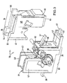
- Rotary double breaker which essentially consists of two fixed contact pieces 6, 7 and a the fixed contact pieces bridging switching element 9 rotatable about an axis 8.
- the fixed contact pieces 6, 7 are each rail-shaped Conductors 10, 11 with appropriate terminals 12, 13 connected.
- the rotatable contact piece 9 is by means of a Shaft 14 pivotable in the direction of arrow 15. For the drive the shaft 14 or to connect the shaft 14 with parallel switched corresponding rotary double breakers for further phases is the shaft 14 through the side wall 16 of the Switch chamber housing 1 out.
- the vertically represented first leg of the respective L-shaped housing module 2 and 3 corresponding first housing part 17 and 18 contains each an extinguishing chamber 19 (Fig.2), within this Arcing chamber 19 both the fixed contact 6 and 7 as well the associated arm 20 or 21 of the rotatable switching element Switch piece 9 is arranged. That the horizontal
- the second housing part 22 shown, forming the second leg or 23 of the respective housing module 2 or 3 is a bearing block designed for the shaft 14 of the rotatable contact piece 9, the side walls 24, 26 or 25 of the second housing part 22 or 23 semicircular openings 27, 29 and 28, which surround the shaft 14.
- the assembly of the entire switching chamber 1 is very simple: In the two finished housing modules 2, 3 are each Extinguishing plates (not shown) and the fixed contact pieces 6, 7 inserted with the rail-shaped conductors 10, 11, assembled and, if necessary, tested the function of the quenching chambers 19. Furthermore, one of the second housing parts 22, 23 the rotatable contact piece 9 inserted and optionally attached. Then the two housing modules 2, 3 connected to each other with the pre-assembled switch contact parts, e.g. screwed, riveted, locked or welded.
Landscapes
- Switch Cases, Indication, And Locking (AREA)
- Breakers (AREA)
Claims (8)
- Boítier de chambre de commutation pour un sectionneur de puissance avec un interrupteur rotatif double, dans lequel l'interrupteur rotatif double comprend deux pièces de contact fixes (6, 7; 37), qui sont chacune reliées par des conducteurs en forme de barres (10, 11; 41, 42) à des bornes de raccordement correspondantes (12, 13; 39, 40), et une pièce de contact (9; 38) à deux bras, tournant autour d'un axe (8), qui, dans sa position fermée, relie l'une à l'autre les deux pièces de contact fixes (6, 7; 37), dans lequel les pièces de contact fixes (6, 7; 37) sont configurées de manière telle qu'en cas de surcharge il se produise entre elles et la pièce de contact rotative (9; 38) parcourue par le courant, à cause des champs magnétiques, des efforts qui basculent la pièce de contact rotative (9; 38) dans une position ouverte, dans lequel une chambre d'extinction (19) est disposée à chaque fois dans la région des pièces de contact fixes (6, 7; 37) pour l'extinction de l'arc électrique qui se forme entre les pièces de contact, et dans lequel le boítier de chambre de commutation (1; 30) est composé de deux modules de boítier (2, 3; 31, 32), caractérisé en ce que les deux modules de boítier (2, 3; 31, 32) sont sensiblement en forme de L et sont tournés l'un vers l'autre par leurs faces transversales intérieures (4, 5), et en ce que les premières parties du boítier (17, 18; 33, 34) correspondant aux premières branches des modules de boítier en forme de L (2, 3; 31, 32) constituent des chambres d'extinction (19).
- Boítier de chambre de commutation suivant la revendication 1, caractérisé en ce que les deux modules de boítier (2, 3; 31, 32) possèdent une structure identique.
- Module de boítier pour la fabrication d'un boítier de chambre de commutation (1; 30) suivant la revendication 1, avec les caractéristiques suivantes:la première partie de boítier (17; 18; 33; 34) formant la première branche du module de boítier (2; 3; 31; 32) en forme de L constitue une chambre d'extinction (19);à l'intérieur de la chambre d'extinction (19) sont disposés aussi bien une des pièces de contact fixes (6; 7; 37) que le bras (20; 21) de la pièce de contact rotative (9; 38) associé à la pièce de contact fixe respective;la seconde partie de boítier (22; 23; 35; 36) du module de boítier (2; 3; 31; 32) formant la seconde branche constitue un support de palier pour un arbre (14) actionnant la pièce de contact rotative (9; 38).
- Module de boítier suivant la revendication 3, caractérisé en ce que les parois latérales (24, 26; 25) de la seconde partie de boítier (22; 23; 35; 36) formant le support de palier présentent des ouvertures semi-circulaires (27, 29; 28).
- Module de boítier suivant la revendication 3 ou 4, caractérisé en ce qu'il est prévu, sur au moins une face extérieure (47, 48; 49, 50) de la première partie de boítier (33; 34) des bords en retrait (45, 46), dans lesquels peuvent être insérés des conducteurs en forme de barres (41; 42) configurés en boucles, disposés entre la pièce de contact fixe respective (37) et la borne de raccordement associée (39; 40).
- Module de boítier suivant la revendication 5, caractérisé en ce que les extrémités des conducteurs (41; 42) en forme de barres, configurés en boucles, sont reliées l'une à l'autre par des nervures de liaison (51, 52).
- Module de boítier suivant la revendication 5 ou 6, caractérisé en ce qu'il est prévu, sur au moins une face extérieure de la seconde partie de boítier (35; 36) dans la région du bord située à l'opposé de la première partie de boítier (33; 34), un retrait (43, 44) dans lequel peut être insérée au moins une portion partielle du conducteur (41; 42) en forme de barre disposé entre la pièce de contact fixe respective (37) et la borne de raccordement correspondante (39; 40).
- Module de boítier suivant l'une quelconque des revendications 3 à 7, caractérisé en ce que le module de boítier (2; 3; 31; 32) se compose d'une pièce moulée en matière plastique.
Applications Claiming Priority (3)
| Application Number | Priority Date | Filing Date | Title |
|---|---|---|---|
| DE19630471A DE19630471A1 (de) | 1996-07-27 | 1996-07-27 | Schaltkammergehäuse für einen Leistungsschalter und Gehäusemodule zur Herstellung eines derartigen Schaltkammergehäuses |
| DE19630471 | 1996-07-27 | ||
| PCT/EP1997/003863 WO1998005049A1 (fr) | 1996-07-27 | 1997-07-18 | Boitier de chambre de commutation pour un sectionneur de puissance et modules servant a fabriquer ce boitier de chambre de commutation |
Publications (2)
| Publication Number | Publication Date |
|---|---|
| EP0916148A1 EP0916148A1 (fr) | 1999-05-19 |
| EP0916148B1 true EP0916148B1 (fr) | 2001-10-04 |
Family
ID=7801111
Family Applications (1)
| Application Number | Title | Priority Date | Filing Date |
|---|---|---|---|
| EP97934489A Expired - Lifetime EP0916148B1 (fr) | 1996-07-27 | 1997-07-18 | Boitier de chambre de commutation pour un sectionneur de puissance et modules servant a fabriquer ce boitier de chambre de commutation |
Country Status (4)
| Country | Link |
|---|---|
| US (1) | US6087609A (fr) |
| EP (1) | EP0916148B1 (fr) |
| DE (2) | DE19630471A1 (fr) |
| WO (1) | WO1998005049A1 (fr) |
Families Citing this family (10)
| Publication number | Priority date | Publication date | Assignee | Title |
|---|---|---|---|---|
| US6621020B2 (en) * | 2000-10-25 | 2003-09-16 | Fuji Electric Co., Ltd. | Breaking mechanism for circuit breaker |
| FR2850203B1 (fr) | 2003-01-20 | 2005-02-25 | Schneider Electric Ind Sas | Boitier de coupure d'un appareil electrique interrupteur |
| US7907389B2 (en) | 2008-08-06 | 2011-03-15 | Egs Electrical Group Llc | Sealed circuit breaker |
| EP2550669B1 (fr) * | 2010-03-26 | 2018-10-17 | Appleton Grp LLC | Disjoncteur étanche |
| US8350168B2 (en) | 2010-06-30 | 2013-01-08 | Schneider Electric USA, Inc. | Quad break modular circuit breaker interrupter |
| CN103403833B (zh) | 2010-08-18 | 2016-09-14 | 艾普顿集团有限责任公司 | 密封的电路断路器 |
| CA2829600C (fr) | 2011-03-10 | 2017-01-03 | Ron Hughes | Enveloppe de protection electrique |
| USD776622S1 (en) * | 2015-02-13 | 2017-01-17 | Layerzero Power Systems, Inc. | Cover |
| CA2937325C (fr) | 2015-08-13 | 2023-10-10 | Layerzero Power Systems, Inc. | Couvercle de borne de disjoncteur et bande de couvercles de borne |
| USD1072776S1 (en) | 2021-07-16 | 2025-04-29 | Layer Zero Power Systems, Inc. | Cover |
Family Cites Families (12)
| Publication number | Priority date | Publication date | Assignee | Title |
|---|---|---|---|---|
| US2100753A (en) * | 1935-12-24 | 1937-11-30 | Westinghouse Electric & Mfg Co | Circuit interrupter |
| DE3431288A1 (de) * | 1984-08-23 | 1986-03-06 | Siemens AG, 1000 Berlin und 8000 München | Kontaktanordnung fuer niederspannungs-leistungsschalter mit einem zweiarmigen kontakthebel |
| US4675481A (en) * | 1986-10-09 | 1987-06-23 | General Electric Company | Compact electric safety switch |
| DE3852455T2 (de) * | 1987-10-01 | 1996-04-18 | Cge-Compagnia Generale Elettromeccanica S.P.A., Mailand/Milano | Hand- und elektromagnetisch betätigbare Kontaktanordnung für strombegrenzende Schalter. |
| FR2622347B1 (fr) * | 1987-10-26 | 1995-04-14 | Merlin Gerin | Dispositif de coupure pour un disjoncteur multipolaire a contact rotatif double |
| DE8903836U1 (de) * | 1989-03-29 | 1989-05-24 | Licentia Patent-Verwaltungs-Gmbh, 6000 Frankfurt | Gehäuse einer Lichtbogenlöschkammer für Niederspannungs-Leistungsschalter |
| DE3910753A1 (de) * | 1989-04-03 | 1990-10-04 | Concordia Sprecher Energie | Mehrfeldriger mittelspannungs-drehschalter |
| FR2648952B1 (fr) * | 1989-06-26 | 1991-09-13 | Merlin Gerin | Disjoncteur limiteur equipe d'un dispositif retardateur de retombee de contact a effet electromagnetique |
| FR2682531B1 (fr) * | 1991-10-15 | 1993-11-26 | Merlin Gerin | Disjoncteur multipolaire a blocs unipolaires. |
| FR2683089B1 (fr) * | 1991-10-29 | 1993-12-31 | Merlin Gerin | Mecanisme de manóoeuvre pour disjoncteur tetrapolaire. |
| FR2688625B1 (fr) * | 1992-03-13 | 1997-05-09 | Merlin Gerin | Contact d'un disjoncteur a boitier moule |
| EP0617449B1 (fr) * | 1993-03-25 | 1997-10-22 | Schneider Electric Sa | Appareil interrupteur |
-
1996
- 1996-07-27 DE DE19630471A patent/DE19630471A1/de not_active Withdrawn
-
1997
- 1997-07-18 WO PCT/EP1997/003863 patent/WO1998005049A1/fr not_active Ceased
- 1997-07-18 EP EP97934489A patent/EP0916148B1/fr not_active Expired - Lifetime
- 1997-07-18 US US09/230,577 patent/US6087609A/en not_active Expired - Fee Related
- 1997-07-18 DE DE59704805T patent/DE59704805D1/de not_active Expired - Fee Related
Also Published As
| Publication number | Publication date |
|---|---|
| US6087609A (en) | 2000-07-11 |
| EP0916148A1 (fr) | 1999-05-19 |
| WO1998005049A1 (fr) | 1998-02-05 |
| DE19630471A1 (de) | 1998-01-29 |
| DE59704805D1 (de) | 2001-11-08 |
Similar Documents
| Publication | Publication Date | Title |
|---|---|---|
| DE69209972T2 (de) | Aus einpoligen Einheiten bestehender Schutzschalter | |
| DE3878429T2 (de) | Mehrpoliger schalter fuer hoeheren strombereich bestehend aus zwei verbundenen formgepressten gehaeusen. | |
| EP0174904B1 (fr) | Dispositif de contact pour disjoncteur basse tension avec un levier de contact à deux bras | |
| DE3888140T2 (de) | Hochkalibriger mehrpoliger Ausschalter mit abgeformtem Gehäuse. | |
| DE69920796T2 (de) | Schutzschalter mit mehreren parallelgeschalteten Schaltkammern pro Phase | |
| DE3621268C2 (de) | Dreiphasig gekapselte, gasisolierte Schaltanlage | |
| DE3732472A1 (de) | Mehrpoliger niederspannungs-leistungsschalter mit einem isolierstoffgehaeuse und lichtbogenloeschkammern | |
| AT400781B (de) | Überspannungsschutzvorrichtung | |
| EP0916148A1 (fr) | Boitier de chambre de commutation pour un sectionneur de puissance et modules servant a fabriquer ce boitier de chambre de commutation | |
| CH618540A5 (fr) | ||
| DE4404706A1 (de) | Bewegliche Kontaktgebervorrichtung in einem Schutzschalter | |
| DE69111571T2 (de) | Mehrpoliger Drehschalter. | |
| EP0003236B1 (fr) | Interrupteur de puissance à basse tension constitué d'un boîtier en matière isolante subdivisé par des parois de séparation | |
| EP0496213B1 (fr) | Disjoncteur, notamment disjoncteur comportant un fusible | |
| EP0205397B1 (fr) | Sectionneur pour une installation interrupteur haute tension blindée et isolée au gaz comprimé | |
| DE69710581T2 (de) | Schaltgerät wie umpolschalter für eine elektrische anlage | |
| DE4336951A1 (de) | Hochspannungsschaltgerät | |
| EP0745260B1 (fr) | Contact de rupture avec des pieces de contact en pont mobiles les unes par rapport aux autres | |
| DE69603000T2 (de) | Elektrische Anschlussleiste | |
| DE2924630A1 (de) | Drehtrennschalter | |
| EP1423862B1 (fr) | Systeme de contacts de commutation comportant un dispositif destine a amplifier une force de contact s'exer ant entre des contacts de commutation | |
| EP0069045A2 (fr) | Socle enfichable pour disjoncteurs de protection multipolaires | |
| EP0177438A2 (fr) | Interrupteur multipolaire avec des boîtiers séparés en matière isolante pour chaque pôle | |
| DE2907559C2 (de) | Dreipoliger Hochspannungsschalter insbesondere Lasttrenner | |
| DE2855205C2 (de) | Mehrpoliges Mittelspannungsschaltgerät mit stufenloser Einstellung von unterschiedlichen Polmittenabständen |
Legal Events
| Date | Code | Title | Description |
|---|---|---|---|
| PUAI | Public reference made under article 153(3) epc to a published international application that has entered the european phase |
Free format text: ORIGINAL CODE: 0009012 |
|
| 17P | Request for examination filed |
Effective date: 19990129 |
|
| AK | Designated contracting states |
Kind code of ref document: A1 Designated state(s): DE FR GB IT |
|
| RAP1 | Party data changed (applicant data changed or rights of an application transferred) |
Owner name: MOELLER GMBH |
|
| GRAG | Despatch of communication of intention to grant |
Free format text: ORIGINAL CODE: EPIDOS AGRA |
|
| 17Q | First examination report despatched |
Effective date: 20000919 |
|
| GRAG | Despatch of communication of intention to grant |
Free format text: ORIGINAL CODE: EPIDOS AGRA |
|
| GRAH | Despatch of communication of intention to grant a patent |
Free format text: ORIGINAL CODE: EPIDOS IGRA |
|
| RIN1 | Information on inventor provided before grant (corrected) |
Inventor name: JUNG, KLAUS Inventor name: ERVEN, WOLFGANG Inventor name: THILKER, LUTZ |
|
| GRAH | Despatch of communication of intention to grant a patent |
Free format text: ORIGINAL CODE: EPIDOS IGRA |
|
| GRAA | (expected) grant |
Free format text: ORIGINAL CODE: 0009210 |
|
| AK | Designated contracting states |
Kind code of ref document: B1 Designated state(s): DE FR GB IT |
|
| REF | Corresponds to: |
Ref document number: 59704805 Country of ref document: DE Date of ref document: 20011108 |
|
| REG | Reference to a national code |
Ref country code: GB Ref legal event code: IF02 |
|
| GBT | Gb: translation of ep patent filed (gb section 77(6)(a)/1977) |
Effective date: 20020108 |
|
| ET | Fr: translation filed | ||
| PLBE | No opposition filed within time limit |
Free format text: ORIGINAL CODE: 0009261 |
|
| STAA | Information on the status of an ep patent application or granted ep patent |
Free format text: STATUS: NO OPPOSITION FILED WITHIN TIME LIMIT |
|
| 26N | No opposition filed | ||
| PGFP | Annual fee paid to national office [announced via postgrant information from national office to epo] |
Ref country code: DE Payment date: 20080722 Year of fee payment: 12 |
|
| PGFP | Annual fee paid to national office [announced via postgrant information from national office to epo] |
Ref country code: IT Payment date: 20080726 Year of fee payment: 12 Ref country code: FR Payment date: 20080715 Year of fee payment: 12 |
|
| PGFP | Annual fee paid to national office [announced via postgrant information from national office to epo] |
Ref country code: GB Payment date: 20080722 Year of fee payment: 12 |
|
| GBPC | Gb: european patent ceased through non-payment of renewal fee |
Effective date: 20090718 |
|
| REG | Reference to a national code |
Ref country code: FR Ref legal event code: ST Effective date: 20100331 |
|
| PG25 | Lapsed in a contracting state [announced via postgrant information from national office to epo] |
Ref country code: FR Free format text: LAPSE BECAUSE OF NON-PAYMENT OF DUE FEES Effective date: 20090731 |
|
| PG25 | Lapsed in a contracting state [announced via postgrant information from national office to epo] |
Ref country code: GB Free format text: LAPSE BECAUSE OF NON-PAYMENT OF DUE FEES Effective date: 20090718 |
|
| PG25 | Lapsed in a contracting state [announced via postgrant information from national office to epo] |
Ref country code: DE Free format text: LAPSE BECAUSE OF NON-PAYMENT OF DUE FEES Effective date: 20100202 |
|
| PG25 | Lapsed in a contracting state [announced via postgrant information from national office to epo] |
Ref country code: IT Free format text: LAPSE BECAUSE OF NON-PAYMENT OF DUE FEES Effective date: 20090718 |