EP0916507A2 - Dispositif pour acheminer des feuilles et appareil d'enregistrement - Google Patents
Dispositif pour acheminer des feuilles et appareil d'enregistrement Download PDFInfo
- Publication number
- EP0916507A2 EP0916507A2 EP98121638A EP98121638A EP0916507A2 EP 0916507 A2 EP0916507 A2 EP 0916507A2 EP 98121638 A EP98121638 A EP 98121638A EP 98121638 A EP98121638 A EP 98121638A EP 0916507 A2 EP0916507 A2 EP 0916507A2
- Authority
- EP
- European Patent Office
- Prior art keywords
- recording
- sheet
- recording apparatus
- outer case
- gear
- Prior art date
- Legal status (The legal status is an assumption and is not a legal conclusion. Google has not performed a legal analysis and makes no representation as to the accuracy of the status listed.)
- Granted
Links
- 239000000463 material Substances 0.000 title claims abstract description 43
- 230000002829 reductive effect Effects 0.000 claims abstract description 13
- 230000002093 peripheral effect Effects 0.000 claims description 12
- 230000000694 effects Effects 0.000 abstract description 8
- 239000000758 substrate Substances 0.000 description 57
- 230000008020 evaporation Effects 0.000 description 28
- 238000001704 evaporation Methods 0.000 description 28
- 238000011084 recovery Methods 0.000 description 25
- 238000000034 method Methods 0.000 description 17
- 238000007599 discharging Methods 0.000 description 13
- 230000006870 function Effects 0.000 description 12
- 239000007788 liquid Substances 0.000 description 12
- 230000004304 visual acuity Effects 0.000 description 9
- 230000007246 mechanism Effects 0.000 description 8
- 238000004891 communication Methods 0.000 description 7
- 239000005030 aluminium foil Substances 0.000 description 6
- 238000010276 construction Methods 0.000 description 6
- 230000035939 shock Effects 0.000 description 6
- 230000005540 biological transmission Effects 0.000 description 5
- 230000003247 decreasing effect Effects 0.000 description 5
- 230000005611 electricity Effects 0.000 description 5
- 238000007639 printing Methods 0.000 description 5
- 230000001105 regulatory effect Effects 0.000 description 5
- 230000003068 static effect Effects 0.000 description 5
- 239000004411 aluminium Substances 0.000 description 4
- 229910052782 aluminium Inorganic materials 0.000 description 4
- XAGFODPZIPBFFR-UHFFFAOYSA-N aluminium Chemical compound [Al] XAGFODPZIPBFFR-UHFFFAOYSA-N 0.000 description 4
- 229920001971 elastomer Polymers 0.000 description 4
- 230000009471 action Effects 0.000 description 3
- 230000001276 controlling effect Effects 0.000 description 3
- 230000000994 depressogenic effect Effects 0.000 description 3
- 239000013013 elastic material Substances 0.000 description 3
- 238000003780 insertion Methods 0.000 description 3
- 230000037431 insertion Effects 0.000 description 3
- 238000007789 sealing Methods 0.000 description 3
- 230000001360 synchronised effect Effects 0.000 description 3
- 238000012360 testing method Methods 0.000 description 3
- VFWCMGCRMGJXDK-UHFFFAOYSA-N 1-chlorobutane Chemical compound CCCCCl VFWCMGCRMGJXDK-UHFFFAOYSA-N 0.000 description 2
- HBBGRARXTFLTSG-UHFFFAOYSA-N Lithium ion Chemical compound [Li+] HBBGRARXTFLTSG-UHFFFAOYSA-N 0.000 description 2
- 239000012790 adhesive layer Substances 0.000 description 2
- 230000006835 compression Effects 0.000 description 2
- 238000007906 compression Methods 0.000 description 2
- 230000000881 depressing effect Effects 0.000 description 2
- 238000010586 diagram Methods 0.000 description 2
- 239000006185 dispersion Substances 0.000 description 2
- 239000000428 dust Substances 0.000 description 2
- 230000005484 gravity Effects 0.000 description 2
- 229910001416 lithium ion Inorganic materials 0.000 description 2
- 238000004519 manufacturing process Methods 0.000 description 2
- 239000004033 plastic Substances 0.000 description 2
- 229920003023 plastic Polymers 0.000 description 2
- 230000009467 reduction Effects 0.000 description 2
- 230000003014 reinforcing effect Effects 0.000 description 2
- 230000004044 response Effects 0.000 description 2
- 238000012546 transfer Methods 0.000 description 2
- 230000037303 wrinkles Effects 0.000 description 2
- RNFJDJUURJAICM-UHFFFAOYSA-N 2,2,4,4,6,6-hexaphenoxy-1,3,5-triaza-2$l^{5},4$l^{5},6$l^{5}-triphosphacyclohexa-1,3,5-triene Chemical compound N=1P(OC=2C=CC=CC=2)(OC=2C=CC=CC=2)=NP(OC=2C=CC=CC=2)(OC=2C=CC=CC=2)=NP=1(OC=1C=CC=CC=1)OC1=CC=CC=C1 RNFJDJUURJAICM-UHFFFAOYSA-N 0.000 description 1
- JOYRKODLDBILNP-UHFFFAOYSA-N Ethyl urethane Chemical compound CCOC(N)=O JOYRKODLDBILNP-UHFFFAOYSA-N 0.000 description 1
- 239000004640 Melamine resin Substances 0.000 description 1
- 229920000877 Melamine resin Polymers 0.000 description 1
- 239000004433 Thermoplastic polyurethane Substances 0.000 description 1
- 230000001133 acceleration Effects 0.000 description 1
- WNLRTRBMVRJNCN-UHFFFAOYSA-N adipic acid Chemical group OC(=O)CCCCC(O)=O WNLRTRBMVRJNCN-UHFFFAOYSA-N 0.000 description 1
- 239000002131 composite material Substances 0.000 description 1
- 230000007797 corrosion Effects 0.000 description 1
- 238000005260 corrosion Methods 0.000 description 1
- 230000003111 delayed effect Effects 0.000 description 1
- 238000013461 design Methods 0.000 description 1
- 238000001514 detection method Methods 0.000 description 1
- 239000003063 flame retardant Substances 0.000 description 1
- 239000006260 foam Substances 0.000 description 1
- 239000006261 foam material Substances 0.000 description 1
- 239000011888 foil Substances 0.000 description 1
- 238000009434 installation Methods 0.000 description 1
- 238000009413 insulation Methods 0.000 description 1
- 239000003562 lightweight material Substances 0.000 description 1
- 230000007774 longterm Effects 0.000 description 1
- 229910052751 metal Inorganic materials 0.000 description 1
- 239000002184 metal Substances 0.000 description 1
- 239000003595 mist Substances 0.000 description 1
- 230000036961 partial effect Effects 0.000 description 1
- 230000000149 penetrating effect Effects 0.000 description 1
- 229920000515 polycarbonate Polymers 0.000 description 1
- 239000004417 polycarbonate Substances 0.000 description 1
- 229920000728 polyester Polymers 0.000 description 1
- 229920000642 polymer Polymers 0.000 description 1
- 230000005855 radiation Effects 0.000 description 1
- 230000001846 repelling effect Effects 0.000 description 1
- 230000002441 reversible effect Effects 0.000 description 1
- 239000004065 semiconductor Substances 0.000 description 1
- 229920002379 silicone rubber Polymers 0.000 description 1
- 239000004945 silicone rubber Substances 0.000 description 1
- 230000006641 stabilisation Effects 0.000 description 1
- 238000011105 stabilization Methods 0.000 description 1
- 229920002803 thermoplastic polyurethane Polymers 0.000 description 1
- 230000032258 transport Effects 0.000 description 1
- 238000011144 upstream manufacturing Methods 0.000 description 1
Images












Classifications
-
- B—PERFORMING OPERATIONS; TRANSPORTING
- B41—PRINTING; LINING MACHINES; TYPEWRITERS; STAMPS
- B41J—TYPEWRITERS; SELECTIVE PRINTING MECHANISMS, i.e. MECHANISMS PRINTING OTHERWISE THAN FROM A FORME; CORRECTION OF TYPOGRAPHICAL ERRORS
- B41J13/00—Devices or arrangements of selective printing mechanisms, e.g. ink-jet printers or thermal printers, specially adapted for supporting or handling copy material in short lengths, e.g. sheets
Definitions
- the present invention relates to a sheet material conveying apparatus and a recording apparatus, and more particularly, it relates to a technique in which rigidity of frames of such apparatuses is enhanced.
- a sheet material such as a paper sheet or a plastic thin plate is conveyed by a sheet material conveying apparatus in response to image information, and an image is recorded on the sheet material by a recording means.
- the recording apparatuses can be grouped into ink jet type, wire dot type, thermal type and laser beam type, in dependence upon a recording system of the recording means.
- Fig. 58 is a sectional explanatory view showing such a compact recording apparatus of portable serial type.
- a recording head 1011 for effecting recording on a recording medium, and the recording medium (sheet material) P is conveyed by a sheet feed roller 1013 along a sheet material convey path H defined by a sheet supply tray 1016, a lower guide 1014 and an upper guide 1015 to be sent to a recording portion M.
- the sheet material on which the recording was effected at the recording portion M is discharged out of the apparatus by a sheet discharge roller 1012.
- the convey path H has a width of 60 to 90% of the width of the recording apparatus.
- the apparatus since the convey path H having the width of 60 to 90% of the width of the recording apparatus forms a tunnel-shaped space in a sheet conveying direction of the apparatus, the apparatus is apt to become weak to an urging force acting from a direction substantially perpendicular to the convey path H.
- the apparatus has greater rigidity.
- Such a compact apparatus is designed also in consideration of the portable ability, and, thus, one of important design factors is to reduce a weight of the apparatus as less as possible. Accordingly, if the rigidity of a frame surrounding the convey path H is merely increased, the weight of the apparatus is increased, or, if light weight material having great strength is used, the apparatus becomes more expensive. Thus, these problems must be solved with good balance.
- the rigidity can be enhanced by a method including "increasing a thickness of an outer frame” or “providing a double-wall outer frame”; however, in case of the portable recording apparatus, both light weight and compactness are required, such a method cannot be used.
- the present invention aims to solve the above-mentioned conventional problems, and an object of the present invention is to provide an apparatus in which a weight and cost are reduced as less as possible and which is strong to load and shock by increasing rigidity of a frame forming the apparatus and in which increase in weight is suppressed to improve portable ability.
- a recording apparatus for recording an image on a sheet material comprising an outer case formed as a box shape, a convey path for conveying the sheet material within the case, a recording means disposed within the case for recording on the sheet material conveyed by the convey path, opening portions provided in the case and defining a sheet inlet and a sheet outlet of the convey path, and a lid member for closing at least one of the opening portions defining the inlet and outlet, and wherein flexion of the outer case is reduced by closing the opening portion by means of the lid member.
- the present invention provides a recording apparatus for recording an image on a sheet material, comprising a convey path for conveying the sheet material, first and second cases opposed to each other with the interposition of the convey path and defining a box-shaped outer case, a recording means disposed within the case and adapted to effect recording on the sheet material conveyed by the convey path, opening portions disposed between the first and second cases and defining a sheet inlet and a sheet outlet of the convey path, and a lid member provided for closing at least one of the opening portions defining the inlet and outlet and selectively shiftable between a first position where the lid member is engaged by an engagement portions provided on the first and second cases to maintain a positional relation between the cases and a second position where the lid member is not engaged by the engagement portion of at least one of the cases.
- a recording apparatus 401 according to an embodiment of the present invention will now be explained with reference to the accompanying drawings.
- the arrangements as conventional ones can be adopted.
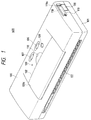
- Fig. 1 is a perspective view of the recording apparatus 401
- Fig. 4 is a sectional view of the recording apparatus.
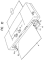
- Fig. 10 is a perspective view of the recording apparatus 401 in a condition that a sheet supply tray 111 is opened
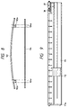
- Fig. 9 is a view showing the sheet supply tray 111 in detail.
- an error release switch 107 for releasing an error condition of the apparatus so that, after a trouble condition of the recording apparatus is removed, the error is released by depressing the error release switch.
- An error lamp 109 for indicating the error condition of the apparatus is turned ON if any of various trouble conditions of the recording apparatus occurs.
- the reference numeral 110 denotes a power lamp for indicating an ON condition of a power source
- 102 denotes a head exchange lid which can be opened when a recording head cartridge arranged within the apparatus is exchanged
- 108 denotes a head exchange switch to be depressed when the recording head cartridge is cleaned
- 111 denotes the sheet supply tray as a lid member
- 106 denotes a power source switch for switching the power source.
- These operation parts are positioned on an upper surface at a center of the recording apparatus so that an operator (user) can manipulate these part from either a left side or a right side.
- a frame (outer wall) of the recording apparatus 401 is constituted by two frame portions (upper case 100 and lower case 101) which will be described later.
- a substrate plate 57 is disposed immediately below the upper case (first frame portion) 100, and the error release switch (input switch of the operation portion), power source switch 106 and lamps 109, 110 are provided on the substrate plate 57. Further, input/output devices of the operation portions, a logic portion for controlling the entire recording apparatus and a power source portion for supplying power to a recording head and the logic portion are provided on the substrate plate 57.
- a battery 116 for supplying an electric power to the substrate plate 57 is detachably mounted to a lower part of the substrate plate 57.
- a recording head cartridge (recording means) 1 is mounted on a carrier 2 shiftable along a guide shaft 5 and a guide rail 12 in a main scan direction.
- the carrier 2 can be shifted reciprocally by a carrier motor 10 via a drive pulley 13 and a belt 11.
- a shifting direction of the carrier 2 is determined by changing the rotational direction of the carrier motor 10.
- the recording head cartridge 1 When the recording head cartridge 1 is of ink jet recording type, it is preferable that a sheet is conveyed substantially horizontally and ink is discharged downwardly so that the ink flow is prevented and a discharging speed of the ink does not interfere with a gravity force.
- the sheet P inserted through a sheet supply opening 121 is passed through a sheet supply path.
- the sheet P is sent to a printing portion M by a sheet feeding roller 6 and a pinch roller 7.
- a sheet discharge roller 15 and a spur roller 16 are provided at a downstream side, and the sheet P is conveyed by using these elements.
- the sheet P on which the recording was effected is pinched between two pairs of sheet discharge rollers 15 and spur rollers 16 and is discharged out of the recording apparatus.
- the direction of the sheet P is determined by two sets of sheet discharge rollers 15 so that, after a trail end of the sheet P leaves the sheet feeding roller 6, the distance between the sheet P and the recording head cartridge 1 is maintained to the constant value.
- the sheet supply tray (lid member) 111 is rotatably connected to the lower case (second frame portion) 101 of the recording apparatus 401.
- a bearing portion 101d provides an engagement portion for the sheet supply tray 111.
- the sheet supply tray 111 has a left guide 111a formed integrally therewith, so that the sheets P are inserted into the sheet supply path of the recording apparatus 401 while guiding left edges of the sheets along the left guide.
- a right guide 112 can be shifted on the sheet supply tray 111 while sliding on the tray with predetermined friction therebetween, so that the right tray is appropriately shifted by the operator in accordance with the width of the sheet P.
- An urging mechanism as shown in Fig. 9 is provided on a shaft portion opposed to the left guide 111a of the sheet supply tray 111.
- a shaft 39 urged by a spring 38 is disposed in a hole of the sheet supply tray 111, thereby generating an urging force directing toward the left guide 111a.
- a width of a fit portion (for the sheet supply tray) of the lower case 101 is designed to become slightly greater than a width of the sheet supply tray 111 in consideration of dispersion in dimensions of parts.
- the entire sheet supply tray 111 is always urged against one side of the lower case 101, thereby preventing occurrence of any play at the left guide 111a side.
- the position of the left guide 111a as a reference for the sheet P is maintained to constant without changing due to margins (occurrence of play) of the width of the fit portion (for the sheet supply tray) of the lower case 101 and the width of the sheet supply tray 111.
- the sheet supply tray 111 When the recording apparatus 401 is not used, the sheet supply tray 111 is closed (first position) as shown in Fig. 2. In a condition that the sheet supply tray 111 is closed, the sheet supply opening 121 (opening portion of the sheet supply path of the apparatus) is closed. Thus, the sheet supply tray 111 acts as both a dust-proof cover and a reinforcing member.
- the sheet supply tray 111 is closed in such a manner that a tip end portion 111b of the tray is inserted into an engagement portion 100d provided on a peripheral edge portion (position near the opening portion of the sheet supply opening) of a sheet supply opening of the upper case 100.
- the sheet supply path creates a tunnel-shaped space in a sheet conveying direction of the recording apparatus 401
- the sheet supply path is apt to be flexed by an urging force from a direction perpendicular to a sheet path.
- the opening portion of the sheet supply path is closed and the tip end portion 111b of the sheet supply tray 111 abuts against the engagement portion 110d to form a beam, thereby strongly opposing to the urging force. Accordingly, in the condition that the sheet supply tray 111 is closed, if the urging pressure acts on both cases 100, 101, the flexion of the cases is suppressed, thereby maintaining the proper positional relation.
- the battery 116 and the substrate plate 57 are positioned at the sheet supply opening 121 side, and the recording portion M has great space due to the existence of the carriage scanning space.
- a gravity center of the apparatus is generally located near the sheet supply opening 121 from the center, when looked at on a line connecting between the sheet supply opening 121 and a sheet discharge opening of the apparatus.
- an outline of the sheet supply tray 111 is constituted by a curved surface.
- the recording apparatus includes the battery 116 therein for use as a portable equipment. Since a length of a human's palm is generally about 70 to 120 mm, in consideration of easy gripping, a thickness of the apparatus is preferably 60 mm or less. Thus, the dimension of the apparatus is selected to have a length of about 300 mm, a width of about 110 mm and a thickness of about 50 mm to permit hand gripping, thereby improving the portable ability.
- a total weight of the recording apparatus is made about 900 g(grams), thereby improving the portable ability.
- Fig. 1 is a perspective view of an ink jet recording apparatus according to an embodiment of the present invention.
- Fig. 2 is a perspective view of the recording apparatus of Fig. 1, looked at from above and oblique direction.
- Fig. 10 is a perspective view of the recording apparatus in a usable condition.
- the upper case 100 covering an upper surface of the recording apparatus
- the lower case 101 covering a lower surface of the recording apparatus, which cases are divided at a sheet passage.
- a pawl 100b is formed on the upper case 100, and a corresponding hook portion 101b is formed on the lower case 101.
- a gap 124 is created between the pawl 100b and the hook portion 101b.
- the gap 124 is normally selected to about 0.2 to 0.5 mm in consideration of dispersion in dimensions of parts and assembling error.
- a projection 101a is formed on a surface of the lower case 101 to be contacted with the upper case 100.
- the gap is eliminated to absorb any play between the upper case 100 and the lower case 101, thereby improving rigidity and preventing noise due to vibration in a printing operation of the recording apparatus.
- the number of parts and the number of assembling steps are reduced, thereby making the recording apparatus cheaper. Further, spaces for the screws can be omitted, thereby making the recording apparatus more compact.
- the head exchange lid 102 is positioned to cover an opening portion 100c of the upper case 100.
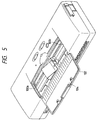
- the opening portion 100c can be opened by opening the head exchange lid 102 as shown in Fig. 5 when a recording head is exchanged or when a sheet jammed within the recording apparatus is removed or when the internal structure of the recording apparatus is cleaned.
- the opening portion 100c is formed in a substantially central portion of the upper case 100 through which a portion of a carriage scan range is exposed (described later). By forming the opening portion 100c in the part of the upper case 100, reduction of rigidity of the upper case 100 can be minimized.
- a head exchange explaining plate 104 is formed from a polyester sheet having a thickness of 0.2 mm on which a method for exchanging the head and the like is printed.
- the reason that the head exchange explaining plate 104 is provided separately from the head exchange lid 102 is that, if the printing is effected on the head exchange lid 102 or a printed matter is adhered to the head exchange lid, in the recycle, the head exchange lid is handled as a foreign matter.
- the head exchange lid 102 is formed as a plate shape having a first face as an outer surface when closed and a second face opposed to a carrier operation portion.
- the head exchange explaining plate 104 is provided on the second face of the head exchange lid 102.
- the head exchange lid 102 is provided with two opposed hooks 102a to which hole portions 104a of the head exchange explaining plate 104 can be engaged and secured.
- the head exchange explaining plate 104 and the head exchange lid 102 are formed to be greater than the opening portion 100c of the upper case 100 by about 2 mm so that they are overlapped with a stepped portion 100a of the opening portion 100c of the upper case 100.
- an end of the head exchange explaining plate 104 is pinched between the head exchange lid 102 and the upper case, thereby preventing the end from suspending to interfere with the carrier 2.
- Fig. 8 shows a method for attaching the head exchange explaining plate 104.
- the head exchange lid 102 is formed from polycarbonate plastic having a thickness of 2 mm and is fitted into the hole portions 104a of the head exchange explaining plate 104 by flexing it as shown in Fig. 8. The flexion of the head exchange lid 102 is released, as shown in Fig. 7, the head exchange explaining plate 104 is attached via the hooks 102a. When discrimination is effected for recycle, the head exchange explaining plate can be dismounted in a manner reverse to the above-mentioned manner.
- the power lamp 110 indicating an ON condition of the power source switch 106 for switching the power source of the recording apparatus.
- the error lamp 109 indicates an error condition of the recording apparatus and is turned ON if any of various trouble conditions of the recording apparatus occurs.
- the error release switch 107 serves to release or remove the error condition of the recording apparatus, so that, after the trouble condition of the recording apparatus is removed, the error is released by depressing the error release switch.
- a hold switch 105 has a function for nullifying the power source switch 106 not to turn ON the power source erroneously when the recording apparatus is transported.
- a power source connector 117 provided on the upper case 100 serves to supply an electric power to the recording apparatus.
- An interface connector 118 for connecting a signal cable from a host computer is covered by an interface connector cover 119.
- the interface connector cover 119 is made of elastic body and has one end forming a hinge portion 119a on the upper case 100 and the other free end.
- the hinge portion 119a is made thinner than the other portion so as to be used as a hinge of the interface connector cover 119.
- Material of the hinge portion 119a thermoplastic polyurethane having good anti-tearing ability and adipate group hardness (Shore hardness) of 85.
- some note-type personal computers have infrared ray communication function. To permit the infrared ray communication, an infrared ray communication window 120 is provided in the vicinity of a flush surface of the interface connector 118 and the lower case 101.
- the sheet is inserted through the sheet supply opening 121 and is discharged from the sheet discharge opening 122.
- the sheet supply tray 111 is closed as shown in Fig. 2, and, in use, the sheet supply tray is opened as shown in Fig. 10 to guide the insertion of the sheet P.
- the sheet supply tray 111 is provided with the left guide (reference for sheet insertion) 111a formed integrally therewith. The left reference position is unchanged regardless of the size of the sheet.
- the right guide 112 for guiding the right edge of the sheet P can be slid by the operator in accordance with the size of the sheet.
- An option connector 58 is provided on a face of the sheet supply opening 121. In the inoperative condition, the option connector 58 is covered by an option connector cover 126.
- an automatic sheet supplying apparatus or feeder (ASF) 127 As an example of option of the recording apparatus, there is an automatic sheet supplying apparatus or feeder (ASF) 127.
- the ASF 127 is provided with an ASF connector 128 connected to the option connector 58.
- the recording apparatus can be connected to the ASF 127 by sliding it in a direction shown by the arrow in Fig. 15. In this case, since the direction of the sheet path and the connecting direction are the same, a space for discharging the sheet is normally maintained in the sheet discharging direction at a place where the ASF 127 is installed. Thus, the mounting of the ASF can easily be effected.
- the recording apparatus is connected to the ASF from a direction perpendicular to the sheet path
- the installation place for the ASF is limited.
- the direction of the sheet path and the connecting and disconnecting direction are the same, the sheet jam treatment can easily be performed.
- the option connector 58 is located in flush with the sheet supply opening 121, the connection to the ASF connector 128 is also effected simultaneously and automatically.
- the time required for the connection can be saved and trouble such as mis-connection and poor insertion can be prevented.
- the recording apparatus includes the battery therein for providing the portable ability. Since the length of the human's palm is about 70 to 120 mm, in consideration of easy gripping, the thickness of the apparatus is preferably 60 mm or less. Thus, the dimension of the apparatus is selected to have the length of about 300 mm, the width of about 110 mm and the thickness of about 50 mm to permit hand gripping, thereby improving the portable ability. Further, by using light weight elements (aluminium pinch roller, hollow sheet feeding roller, hollow guide shaft, lithium ion battery having good volume efficiency), the total weight of the recording apparatus is made about 900 grams, thereby improving the portable ability.
- light weight elements aluminium pinch roller, hollow sheet feeding roller, hollow guide shaft, lithium ion battery having good volume efficiency
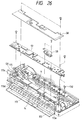
- Figs. 26 and 27 are perspective view showing an internal construction of the recording apparatus according to the embodiment of the present invention.
- a platen 14 constitutes a part of a recovery system (described later) and a lower part of a sheet feeding portion.
- a frame 4 made of aluminium to achieve light weight purpose holds a carrier operation portion (described later) and an upper part of the sheet feeding portion to define the recording apparatus.
- the platen 14 and the frame 4 are positioned to each other by fitting bosses of the platen 14 provided on left and right side at the sheet discharge side into notched portions of the frame 4 provided on left and right side at the sheet discharge side and are secured to each other by hooking the frame 4 to pawl portions of the platen 14 provided on left and right side at the sheet supply side.
- a substrate holder 113 shown in Figs. 26 and 27 is positioned at the sheet supply side of the frame 4 by two bosses (not shown) and is secured by three upper pawls and a lower central screw.
- the substrate holder 113 has a function for detachably holding the battery 116, a function for holding the substrate plate 57, a function for guiding an upper path when the sheet P is supplied and the like.
- a battery contact 115 having four male terminals is welded to a battery substrate (not shown) outside of a left wall of the substrate holder 113, looked at from the sheet supply side for the sheet P.
- the male terminals of the battery contact 115 protrude into a substrate holder recess 113b into which the battery 116 is housed.
- a battery cable 131 from the battery substrate is connected to the substrate plate 57 via a battery connector 132.
- a substrate holder rail 113a substantially parallel with a sheet pass direction and provided on the substrate holder 113, and a battery hook 125 slidable for extension and retraction.
- the battery hook 125 is extended and retracted in synchronous with a sliding movement of a battery lock lever 114.
- the battery hook 125 is normally held in an extended condition by a battery lock spring (not shown).
- a battery stepped portion 116a in correspondence to the substrate holder recess 113b of the substrate holder 113, and a female battery contact 116b is located at a position where it is connected to the battery contact 115.
- a battery groove 116c is located at a position corresponding to the substrate holder rail 113a and a battery recess 116d is located at a position corresponding to the battery hook 125.
- the battery stepped portion 116a of the battery 116 is inserted into the substrate holder recess 113b of the substrate holder 113.
- the battery contact 115 and the female battery contact 116b are contacted with each other, and, when the battery 116 is rotated in a direction shown by the arrow A in Fig. 28 while inserting the battery groove 116c onto the substrate holder rail 113a until the groove abuts against the rail, the battery hook 125 is fitted into the battery recess 116d by the spring force of the battery lock spring (not shown) and is secured therein.
- a battery pop-up 60 near the battery hook 125 is biased by a battery pop-up spring 61 toward a direction along which the battery 116 is pushed out.
- the battery hook 125 is driven to disengage from the battery recess 116d, with the result that the battery pop-up 60 is protruded in a direction shown by the arrow C in Fig. 28 by the spring force of the battery pop-up spring 61, thereby pushing out the battery 116. Consequently, the battery 116 is rotated in a direction shown by the arrow B in Fig. 28 around the battery contact 115 and the female battery contact 116b, thereby disengaging the battery 116.
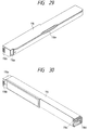
- the battery 116 will be briefly described with reference to Figs. 29 and 30.
- battery cells are arranged in series and are covered by a welded lid.
- a battery rib 116e is provided at a front upper part of the battery 116 to prevent entrance of dust when the sheet supply tray 111 is closed.
- a central portion of the battery rib 116e is curved and is slightly bent downwardly not to interfere with the operator's finger when the sheet supply tray 111 is opened.
- a function of the recording apparatus for supplying the sheet P will be explained.
- front lower portions (looked at from the sheet supply side of the sheet P) of the substrate holder 113 and the battery 116 are curved to facilitate the sheet supply.
- a supply path for the sheet P is defined by the platen 14 (at a lower side) and the substrate holder 113 and the battery 116 (at an upper side).
- the substrate holder 113 and the battery 116 also act as a guide of the sheet supply path.
- substrate holder bosses 113c are formed on left and right upper parts of the substrate holder 113 at a front sheet supply side.
- the substrate holder bosses 113c are inserted into holes of the substrate plate 57 to position and support the substrate plate 57.
- the rear side of the substrate plate 57 is secured to the frame 4 by two left and right screws. At this position, the substrate plate 57 is grounded.
- the option connector 58 is secured to the substrate holder 113 by two screws.
- a sheet sensor 25 is held at a lower part of the substrate holder 113 where the sheet P is passed.
- a memory back-up secondary battery (not shown) is housed in a space surrounded by the substrate holder 113.
- a substrate holder hole 113d is formed in the substrate holder 113 at the left side thereof and a substrate holder elongated hole 113e is formed in the substrate holder at the right side thereof, which holes serve to position the ASF 127.
- the shield plate 56 is constituted by an upper conductive shield plate aluminium foil 56b and a lower insulation shield plate PET 56a.
- the aluminium foil 56b and the PET 56a are bonded together by a shield plate adhesive layer 56c.
- the shield plate 56 is secured to the frame 4 by two screws and is electrically connected to the frame 4 by contacting the screws with the upper aluminium foil 56b.
- the frame 4 is electrically connected to a ground (not shown).
- the shield plate 56 covers the upper surface of the substrate plate 57 to shield radiation noise generated from the substrate plate 57. Under a low humidity condition, static electricity may be accumulated in the operator, and, when the operator manipulates the recording apparatus, atmospheric discharge to the recording apparatus may occur.
- the voltage of the atmospheric discharge may reach up to 40 kV. If the voltage is discharged to the pattern on the substrate plate 57, elements on the substrate plate 57 will be destroyed or erroneous operation will occur. Also in such a case, since the substrate plate 57 is covered by the shield plate 56, the static electricity is flowing to the ground through the aluminium foil 56b, thereby protecting the substrate plate 57.
- a thickness of the shield plate aluminium foil 56b is about 50 ⁇ m
- a thickness of the shield plate PET 56a is about 100 ⁇ m
- a thickness of the shield plate adhesive layer 56c is about 40 ⁇ m.
- Arrangement of the upper case 100, power source switch 106, error release switch 107, shield plate 56 and substrate plate 57 will be explained with reference to Fig. 25 (sectional view).
- the power source switch 106 and the error release switch 107 are elastically attached so that the operation faces of these switches protrude from the holes 100d of the upper case 100.
- Contact switches 57b are provided on the substrate plate 57 via the shield plate 56 immediately below the power source switch 106 and the error release switch 107. Accordingly, the contact switch 57b corresponding to the power source switch 106 arranged on the substrate plate 57 and the contact switch corresponding to the error release switch 107 are depressed via the shield plate 56.
- a contact switch (not shown) corresponding to the head exchange switch is also depressed via the shield plate 56.
- the holes 100d are formed to be greater than the power source switch 106 and the error release switch 107 by about 0.2 mm in dimension so as not to interfere with the latter.
- the recording apparatus has the carrier 2 for detachably holding the recording head cartridge 1.
- the carrier 2 is supported by the guide shaft 5 and the guide rail 12 which have both ends secured to the frame 4 and are disposed in parallel with each other in such a manner that the carrier is located perpendicular to the sheet conveying direction and can be slid in the main scan direction parallel with the surface of the sheet P.
- the guide shaft 5 is formed from a pipe-shaped hollow shaft having a thin wall.
- a look arm 370 and a plug 5a having a groove for securing the guide shaft 5 to the frame 4 are secured within one end of the guide shaft 5.
- the carrier 2 is connected to a portion of a belt 11 mounted between a drive pulley 13 rotating driven by a carrier motor 10 secured to the frame 4 and an idle pulley slidable in a direction parallel to the guide shaft 5 and rotatably supported by the frame 4 via a spring (not shown), so that, when the carrier motor 10 is energized, the belt 11 is driven to reciprocally shift the carrier in the above-mentioned direction along the guide shaft 5 and the guide rail 12.
- An ink tank 8 is detachably mounted on the recording head cartridge 1 so that, when ink is used up by the recording, the ink tank 8 can be exchanged. Further, the recording apparatus has a home position sensor 26 for detecting the position of the carrier 2 by detecting the passage of the carrier 2, and a flexible cable 3 for transmitting an electric signal from the substrate plate 57 to the recording head cartridge 1.
- a sheet feeding roller 6 is rotatably supported by the frame 4, and an LF gear 18 is secured to an end of a shaft of the sheet feeding roller 6.
- the sheet feeding roller 6 is a pipe-shaped hollow shaft having a thin wall and coated by urethane. As shown in Fig. 55, the pipe has an outer diameter D2 of about 7.561 mm, an inner diameter d2 of about 5 mm and a wall thickness t of about 1.28 mm.
- the sheet feeding roller 6 is rotatingly driving by a sheet feeding motor 23 via the LF gear 18.
- the above-mentioned dimensions are determined in consideration of manufacturing run-out accuracy, outer peripheral tolerance, light weight and shock strength.
- the outer diameter D2 of the sheet feeding roller 6 is selected by the following reasons.
- the outer diameter D2 is so selected that, when the sheet feeding motor 23 is rotated by one step, the sheet P is fed by the sheet feeding roller 6 by 1/360 inch.
- the wall thickness of the pipe In order to make the sheet feeding roller 6 having the outer diameter D2 lighter as less as possible and to provide the shock strength of the frame 4, the wall thickness of the pipe must be made thinner. On the other hand, when it is manufactured so that the run-out accuracy of the sheet feeding roller 6 and flexion due to pinch pressure receiving four pinch rollers 7 do not affect an influence upon sheet feeding accuracy, the greater wall of the pipe more the sheet feeding roller is stabilized. By balancing these two conditions, the thickness of the pipe is determined, with the result that the inner diameter d2 is also determined.
- Fig. 4 is a sectional view of the recording apparatus.
- a lower side of the sheet conveying path is defined by the platen 14.
- the platen 14 is incorporated along the inner wall of the lower case 101 and has a box shape for providing a space for containing a disposal ink absorbing body 327 (described later) between the platen and the lower case 101.
- a plurality of rows of protruded ribs (not shown) for reducing adhesion of the sheet P to the platen due to the static electricity and the sliding load during the sheet conveyance are formed on the surface of the platen 14 along the sheet conveying direction.
- the pinch roller 7 held by a pinch roller holder 9 rotatably attached to the platen 14 is urged against the sheet feeding roller 6 from the below by a spring (not shown), so that the sheet P pinched between the sheet feeding roller 6 and the pinch roller 7 is conveyed by driving the sheet feeding motor 23.
- an outer peripheral portion D1 of the pinch roller 7 for pinching the sheet between it and the sheet feeding roller 6 has a diameter of about 6 mm substantially equal to or slightly smaller than the sheet feeding roller 6. Further, a ratio between an outer diameter d1 of a rotary shaft portion 7a held by the pinch roller holder 9 and the diameter D1 of the outer peripheral portion of the pinch roller 7 is 2 : 15, and, thus, the shaft diameter d1 is 0.8 mm.
- the sheet feeding roller 6 is made of aliminium (light weight metal). Thus, since the sheet feeding roller 6 has light weight and less rotational load, there is almost no sheet feeding loss.
- the outer diameter D1 of the pinch roller 7 and the outer diameter D2 of the sheet feeding roller 6 are substantially the same, when the sheet is supplied, the sheet P can easily be directed to a nip 33 between the pinch roller 7 and the sheet feeding roller 6. Thus, a pushing force for penetrating the tip end of the sheet into the nip 33 can be reduced.
- the outer peripheral portion and the shaft portion of the pinch roller 7 made of aluminium are both subjected to allodine treatment, so that corrosion of these parts due to the presence of ink mist discharged from the recording head cartridge 1 and included in the atmosphere within the apparatus and wear of the outer peripheral portion when it is driven for a long time while contacting with the pinch roller 7 are reduced, with the result that the rotational load of the pinch roller 7 is almost not increased even after the long term use.
- Figs. 3 and 4 two rows of sheet discharge rollers 15 for discharging the recorded sheet out of the apparatus are attached at an opposite side of the sheet feeding roller 6 with the interposition of the recording head cartridge 1.
- the sheet discharge rollers 15 are rotated in synchronous with the sheet feeding roller 6 by transmitting a driving force from the sheet feeding roller 6 through an idle gear train 21.
- the spur rollers 16 attached to the guide rail 12 are located above the sheet discharge rollers 15, and the sheet discharge rollers 15 are urged against the spur rollers 16 from the below by springs (not shown) so that the sheet is pinched between and conveyed by the sheet discharge rollers and the spur rollers.
- the sheet sensor 25 is disposed at an upstream side of the sheet feeding roller 6 at the side of the sheet supply opening 121 remote from the recording head cartridge 1 and a discharge sheet sensor 17 is disposed between two rows of sheet discharge rollers 15, thereby detecting presence/absence of the sheet P.
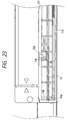
- Fig. 23 is a front view of the sheet supply opening 121 of the recording apparatus according to the illustrated embodiment.
- the platen 14 is provided at its left end with a sheet guide portion 14a acting as a reference when the sheet is inserted.
- a rib 14b nearest to the sheet guide portion 14a has a smooth inclined surface or slope only at a side opposite to the sheet guide portion 14a in order to prevent the sheet from being caught by the rib when the sheet is directed toward the sheet guide portion 14a.
- the platen 14 has a recess 14c for containing a tip end of the sheet sensor when the sheet is not inserted.
- the sheet sensor 25 has a tapered portion 25a at a side opposite to the sheet guide portion 14a.
- the function of the recording apparatus is to effect one-line recording on the sheet by discharging the ink downwardly (in Fig. 3) from the recording head cartridge 1 in response to a recording signal in synchronous with the reciprocal movement of the carrier 2. That is to say, the recording head cartridge 1 has fine liquid discharge openings (orifices), liquid passages, energy acting portions provided within the liquid passages, and energy generating means for generating liquid droplet forming energy acting on the liquid in the acting portions.
- a recording method utilizing such energy generating means a recording method using electrical-mechanical converters such as piezo-electric elements, a recording method in which heat is generated by radiating a electromagnetic wave such as laser and a liquid droplet is discharged by the action of the heat, or a recording method in which liquid is heated by an electrical-thermal converter such as a heat generating element having heat generating resistance thereby to discharge the liquid may be used.
- a recording head used in an ink jet recording method for discharging liquid by thermal energy since liquid discharge openings for discharging recording liquid to form a discharge liquid droplet can be arranged with high density, recording with high resolving power can be performed.
- a recording head using an electrical-thermal converter as an energy generating source can easily be compact, can fully utilize merits of IC techniques and micro-working techniques in which progress of technique and reliability have remarkably been enhanced in a semi-conductor field, can be mounted with high density and can be manufactured cheaply.
- the sheet is conveyed by one line by means of the sheet feeding motor 23 in the conveying direction shown by the arrow in Fig. 10, and then, the next one-line recording is effected.
- a recovery portion has a recovery mechanism (described later) for removing the ink and/or foreign matters accumulated in the nozzles of the recording head cartridge 1. Further, a preliminary discharge operation for removing a small amount of foreign matters and/or ink remaining in the nozzles after the recovery operation is effected. In the preliminary discharge operation, the driving of the recording head for performing normal printing is effected at a predetermined position other than the surface of the sheet P. Disposal ink discharged by these operations is absorbed by the disposal ink absorbing body 327 incorporated into the inner wall of the platen 14.
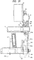
- Fig. 31 is a view showing a piston drive transmitting path from the sheet feeding motor 23 to the recovery system of the ink jet recording apparatus.
- the rotation of the sheet feeding motor 23 is transmitted from the LF motor gear 30 and the LF double gear 31 to the LF gear 18 to rotate the sheet feeding roller 6.
- a trigger gear 32 slidingably and rotatably mounted on the sheet feeding roller 6 in coaxial therewith
- a clutch switching projection 2c formed on the carrier 2 the trigger gear 32 is shifted toward the LF gear 18, with the result that a driving force of the LF gear 18 is transmitted to the trigger gear 32 due to engagement which will be described later.
- the trigger gear 32 is meshed with a pump gear 316, the driving force is transmitted to the pump gear 316.
- the trigger gear 32 is separated from the LF gear 18 and a non-toothed portion of the pump gear 316 is located at an engagement position between the pump gear and the LF gear 18, the driving force from the LF gear 18 is not transmitted to the pump gear 316.
- the carrier 2 is shifted to a capping position, where the ink discharge openings of the recording head cartridge 1 is covered or closed by a cap 317.
- the pump gear 316 shifts a piston in a cylinder 321 via a cylinder gear 361, with the result that the ink is absorbed from the ink discharge openings of the recording head cartridge 1 into the cylinder 321 through the cap 317, thereby recovering the ink discharging function of the recording head cartridge 1.
- the transmission of the driving force from the sheet feeding motor 32 to the pump gear 316 is controlled by the pump gear 316, LF gear 18, trigger gear 32 and carrier 2.
- Fig. 32 is an enlarged view showing a switching mechanism of the ink jet recording apparatus and therearound.
- the trigger gear 32 is slidably provided on the sheet feeding roller 6 in coaxial therewith.
- the trigger gear 32 is meshed with the pump gear 316.
- the driving force from the LF gear 18 is not transmitted to the trigger gear 32.
- the non-toothed portion of the pump gear 316 is opposed to the LF gear 18, the pump gear does not receive the driving force of the LF gear 18.
- the trigger gear 32 is further shifted toward the LF gear 18 to contact with the LF gear 18.
- Opposed side surfaces of the trigger gear and of the LF gears are provided with triangular teeth which are to be engaged by each other.
- Figs. 33A, 33B, 34A and 34B are views showing the engagement condition between the LF gear 18 and the trigger gear 32. More specifically, Fig. 32 shows a contact surface configuration 18a of the LF gear 18 to be contacted with the trigger gear 32, and Fig. 34B shows a contact surface configuration 32a of the trigger gear 32 to be contacted with the LF gear 18.
- the contact teeth configurations shown in Figs. 33B and 34B are looked at from directions shown by the arrows.
- the contact surface configuration is constituted by triangle-shaped teeth 18a (referred to as "triangular teeth” hereinafter) each having pitch angles ⁇ same as those of gears 18b and tooth bottoms aligned with those of the teeth 18b.
- triangular teeth 32a constituting the contact surface configuration same as the contact surface configuration 18a of the LF gear 18 have pitch angle ⁇ same as those of gears 32b and tooth tips aligned with tooth bottoms of the gear 32b.
- the pitch angle means an angle of a space (pitch) between adjacent teeth with respect to a center of the gear.
- a wider notched portion 316a extending in a radial direction are formed on the peripheral portion of the pump gear 316. That is to say, the pump gear 316 has thicker portions than the trigger gear 32 and the LF gear 18, and, further, the peripheral portion of the pump gear 316 is provided with the notched portion having teeth parts of which are notched from the vicinity of an axial center toward one end direction (shown by the arrow E in Fig. 32).
- Figs. 35 and 36 are views showing a positional relation between the pump gear and the trigger gear 32, and Fig. 35 is a view looked at from the right side in Fig. 31 and Fig. 35 is a view looked at from the left side in Fig. 31.
- a width of the notch (shown by the arrow F in Fig. 36) is selected so that, even when the pump gear 316 and the LF gear 18 are in the engagement position, the notched portion 316a is not contacted with the LF gear 18.
- the pump gear 316 is rotated to shift the notched portion, with the result that the pump gear 316 is directly engaged by the LF gear 18, thereby providing the great driving force.
- the driving force continues to be transmitted.
- the trigger gear 32 is disengaged from the LF gear 18 while shifting in the condition that the trigger gear is still engaged by the pump gear 316, there is no problem regarding interfere between the teeth due to the shifting of the trigger gear 32. Since the engagement condition between the pump gear 316 and the trigger gear 32 is not required at the time when the pump gear 316 is engaged by the LF gear 18, an engagement area (hatched portion indicated by the arrow G in Fig. 36) of the pump gear 316 regarding the trigger gear 32 may be greater than at least the notched area. With this arrangement, since the width of the gear other than the engagement portion of the pump gear 316 regarding the trigger gear 32 can be reduced, another mechanism or parts can be installed in such a width-reduced section.
- the triangular teeth formed on the contact surfaces of these gears are engaged by each other. From this condition, even when the carrier 2 is separated from the trigger gear 32 and the LF gear 18 is rotated, the driving force is directly transmitted between the LF gear 18 and the pump gear 316. Since the driving force is not transmitted to the trigger gear 32, the trigger gear 32 tries to maintain the engagement condition between the trigger gear and the LF gear 18 (Actually, the engagement condition may be released due to vibration or the like).
- the LF gear 18 is rotated reversely in order to release the drive transmission from the LF gear 18 to the pump gear 316.
- the notched portion 316a of the pump gear reappears again, and, at the same time, the engagement portion (G in Fig. 36) of the pump gear 316 regarding the trigger gear 32 is engaged by the trigger gear 32 again.
- the direct drive transmission between the pump gear 316 and the LF gear 18 ceases, thereby stopping the pump gear 316.
- Figs. 37 to 43 are explanatory views for explaining an operation of the recovery system according to the illustrated embodiment.
- the cap 317 made of butyl chloride rubber or other appropriate material having elasticity is integrally held on a cap holder 341.
- the cap holder 341 is rotatably connected to the arm portion 321a of the cylinder 321 via a connection pin 341b provided on the cap holder 341.
- the cylinder 321 includes a piston 342 made of elastic material such as rubber therein, so that negative pressure can be generated within the cylinder 321 by driving a piston shaft 343. Movements of the piston shaft 343 and the piston 342 will be described later.
- a joint portion 317a is integrally formed with the cap 317. By fitting the joint portion 317a onto a joint portion 321b of the cylinder 321 with interference, the cylinder 321 and the cap 317 are interconnected in a sealed condition. An ink suction opening for communicating the interior of the cylinder with the cap 317 is formed within the joint portion 321b of the cylinder 321.
- the cap 317 integrally held on the cap holder 341 as mentioned above is sealingly connected to the cylinder 321, and the cap holder 341 is rotatably held by the arm portion 321a of the cylinder 321.
- the cap 317 and the cylinder 321 are interconnected via the joint portions 317a, 321b, since the joint portion 317a is made of elastic material such as butyl chloride rubber and is integrally formed with the cap 317 and has an L-shape which can be deformed, the rotation of the cap holder 341 is not obstructed (refer to Figs. 38, 39 and 40).
- a different diameter compression cap spring 344 is disposed between the platen 14 and the cap holder 341 to always bias the cap holder 341 toward the recording head cartridge.
- the cylinder 321 is supported by the platen for rotation around a cylinder axis. Accordingly, the cylinder 321 and the cap 317 are subjected to a rotating force from the different diameter compression cap spring 344 for rotation around the cylinder axis.
- a cylinder control portion 321d is integrally formed with the cylinder 321, and a tip end of the cylinder control portion 321d abuts against a cap control cam portion (first cam member) 316b of the pump gear 316. Accordingly, the rotation of the cylinder is controlled by the cap control cam portion 316b of the pump gear 316 via the cylinder control portion 321d. That is to say, by shifting the cylinder control portion 321d upwardly and downwardly along the cap control cam portion 316b of the pump gear 316, the capping and uncapping of the cap 317 with respect to the recording head cartridge 1 can be effected via the cylinder 321.
- Figs. 38 and 39 show a condition that the cap 317 is engaged by the recording head cartridge 1
- Fig. 40 shows a condition that the cap 317 is disengaged from the recording head cartridge 1.
- the entire length of a cap control spring 318 is regulated by a spring regulating portion 14d of the platen 14 so that the cap control spring is spaced apart from the lower surface of the cap holder 341. Accordingly, the engagement condition of the cap 317 is not influenced upon the cap control spring.
- Fig. 40 shows a condition that the cylinder 321 is rotated by the rotation of the pump gear 316 to separate the cap 317 from the recording head cartridge 1.
- the cap control spring 318 abuts against the lower surface of the cap holder 341 to provide a clockwise rotating force on the cap holder 341.
- the cap holder 341 is rotated in a clockwise direction until a stopper 341a of the cap holder 341 abuts against the arm portion 321a of the cylinder.
- the pump gear 316 can selectively be connected to the LF gear 18 so that the driving force of the sheet feeding motor (not shown) is transmitted to the LF gear 18 through a gear train (not shown). Thereafter, when the clutch operation is performed by the movement of the carrier 2, the driving force transmitted to the LF gear 18 is transmitted to the pump gear 316. When the clutch operation is not performed by the carrier 2, since the non-toothed portion is provided in the pump gear 316, the driving force of the LF gear 18 is not transmitted to the pump gear 316.
- the pump gear 316 is engaged by a cylinder gear 361. That is to say, when the clutch operation is performed by the carrier 2, the rotation of the LF gear 18 is transmitted to the pump gear 316 and then is transmitted to the cylinder gear 361. Further, a boss 361a provided on an inner wall of the cylinder gear 361 is received in a lead groove 343a formed in the piston shaft 343 and guides 321e of the cylinder 321 are fitted into grooves 343b provided at a tip end of the piston shaft 343 so that rotation of the piston shaft 343 is prevented, thereby converting the rotational movement of the pump gear 316 into a straight movement of the piston shaft 343.
- Two flange portions 343c, 343d are integrally formed with the piston shaft 343.
- a doughnut-shaped piston 342 having a central through hole and made of elastic material such as silicone rubber, NBR rubber or the like is disposed between the flanges.
- the cylinder 321 and the piston 342 are cylindrical, and an outer diameter of the piston 342 is greater than an inner diameter of the cylinder 321 to provide any interference (about 0.2 to 0.5 mm) therebetween. Accordingly, during the shifting movement of the piston 342, the sealing ability can be maintained between the inner wall of the cylinder and the outer wall of the piston.
- a cylinder seal 345 has a doughnut shape, and an outer diameter of the cylinder seal 345 is selected to provide a sealing ability between the seal and the inner wall of the cylinder and an inner diameter of the cylinder seal 345 is selected to provide a sealing ability between the seal and the piston shaft 343.
- a cylinder washer 346 is locked to a different diameter portion of the cylinder 321.
- a circumferential rib 342a is formed on a side surface of the piston 342 in a confronting relation to the flange 343c, and an inner diameter of the piston 342 is greater than an outer diameter of the piston shaft 343 to provide a gap therebetween. Further, a distance between two flanges provided on the piston shaft 343 is greater than a width of the piston 342. Such gaps contribute to the discharging of the sucked ink, which will be described later. As shown in Fig. 37, in an initial condition of the pump, the piston shaft is lifted to urge the piston 342 against the flange 343d (Fig. 37).
- cap control cam portion 316b of the pump gear 316 so that when the piston 342 passes through the ink suction opening 321c the recording head cartridge 1 is sealingly closed by the cap 317, the ink can be sucked.
- the ink absorbed from the recording head cartridge 1 is accumulated in the space 321f of the cylinder. Then, when the motor is driven reversely, the piston shaft 343 is shifted to the right shown by the arrow B in Fig. 43. As a result, since the width of the piston 342 is smaller than the distance between the flanges of the piston shaft 343 and the inner diameter of the piston is greater than the outer diameter of the piston shaft 343, as the piston shaft 343 (piston 342) is shifted to the right, the ink within the space 321f flows a space 321h at a left side of the piston 342 through the gap between the piston 342 and the piston shaft 343 (as shown by the arrows C in Fig. 43).
- the ink is gradually discharged through an end 321g of the cylinder 321.
- a cylinder absorbing body 326 is inserted into the cylinder end 321g.
- the cylinder absorbing body 326 is formed from material having good ink transferring ability such as foam sponge. That is to say, an ability for effectively discharging the ink in the cylinder 321 outside is required for the cylinder absorbing body, and, thus, in the illustrated embodiment, the cylinder absorbing body is formed from foam material of melamine resin group.
- the cylinder absorbing body 326 is contacted with the disposal ink absorbing body 327 contained within the platen 14.
- the disposal ink absorbing body 327 is formed from material having high ink holding ability such as a laminated sheet or a polymer absorbing body.
- the disposal ink absorbed from the recording head cartridge 1 is transmitted to the disposal ink absorbing body 327 through the cylinder and the cylinder absorbing body 326 and is held therein.
- a volume of the disposal ink absorbing body 327 itself is about 120 cm 3 , and it was found from tests that an amount of ink which can be held by the disposal ink absorbing body is about 84 cm 3 (about 70% of the body volume).
- Fig. 44 shows a released condition of the lock arm according to the illustrated embodiment, looked at from the left in Fig. 31.
- Fig. 45 shows a locked condition of the lock arm, looked at from the left in Fig. 31.
- Fig. 46 shows a carrier releasing condition obtained by the lock arm 370, looked at a front side in Fig. 31.
- Fig. 47 shows a carrier locking condition obtained by the lock arm according to the illustrated embodiment, looked at from the front side in Fig. 31.
- the cap control cam portion 316b for controlling the opening and closing of the cap 317 via the arm portion 321a of the cylinder 321 is provided on the left (Fig. 31) side surface of the pump gear 316.
- the right (Fig. 31) side surface of the pump gear 316 is provided with a groove-shaped lock control cam portion (second cam member) 316d for engaging by a boss portion 370a of the lock arm 370 and for effecting locking and unlocking of the carrier 2 via the lock arm 370.
- the boss portion 370a of the lock arm 370 is engaged by the lock control cam portion 316d of the pump gear 316.
- Figs. 44 and 45 the boss portion 370a of the lock arm 370 is engaged by the lock control cam portion 316d of the pump gear 316.
- the lock arm 370 is arranged within a range substantially equal to a width of the gear train including the LF gear 18 and the pump gear 316 at the right part of the apparatus and is disposed outside of the shifting movement range of the carrier 2 on which the recording head cartridge 1 is mounted.
- a rotation center portion 370b of the lock arm 370 is formed as a bearing a part of which is opened, and is rotatably supported on the guide shaft 5.
- the rotation center portion 370b has elasticity and is supported on the guide shaft 5 by forcibly fitting the opened portion of the rotation center portion 370b onto the guide shaft 5 from the above.
- the boss portion 370a is provided substantially at a central portion of the lock arm 370 and is engaged by the lock control cam portion 316d of the pump gear 316.
- the lock arm 370 extends from the rotation center portion 370b toward the boss portion 370a and is provided with a lock portion 370c.
- the lock portion 370c of the lock arm 370 is formed as an L-shape at a tip end of the elongated member extending from the rotation center portion 370b toward the boss portion 370a.
- the lock portion 370c is provided with a carrier fixing portion 370d engageable with a lock projection 2d of the carrier 2 and a regulating portion 370e engageable between an arm engaging portion 12a of the guide rail 12 and the frame 4.
- the pump gear 316 exists in an initial condition as shown in Fig. 44.
- the driving force of the LF gear 18 is not transmitted to the pump gear 316 and the cap (not shown) is uncapped or released by the cap control cam portion 316b.
- the lock arm 370 is lifted upwardly around the rotation center portion 370b by the boss portion 370a and the lock control cam portion 316d of the pump gear 316.
- the lock portion 370c is located at an elevated position.
- Fig. 46 shows a positional relation between the L-shaped portion of the lock portion 370c and the carrier 2.
- the carrier fixing portion 370d is positioned above the lock projection 2d of the carrier 2 so that the carrier 2 can be shifted.
- the pump gear 316 is capped as shown in Fig. 45. That is to say, the lock arm 370 is lowered downwardly by lowering the boss portion 370a by means of the pump gear 316 and the lock control cam portion 316d. The lock portion 370c is also lowered. In this condition, Fig. 47 shows an engagement condition between the L-shaped portion of the lock portion 370c and the carrier 2. The carrier fixing portion 370d is engaged by the lock projection 2d and not to permit the shifting movement of the carrier 2. Further, the regulating portion 370e is located between the arm engaging portion 12a of the guide rail 12 and the frame 4.
- a tip end 370f of the lock arm 370 is located at the left of the cap 317.
- the carrier 2 is separated from the cap 317 for any reason to position the cap at a position same as the position where the cap 317 is mounted to the carrier 2, when the carrier 2 tries to be forcibly shifted to the cap position, since the cap 317 is in a convex condition, the cap 317 may be damaged by the carrier 2 and the recording head cartridge 1 or the recording head cartridge 1 may be damaged by the cap 317.
- the tip end 370f of the lock arm 370 since the tip end 370f of the lock arm 370 is extended, the lock projection 2d of the carrier 2 is prevented from shifting the cap mounting position by the tip end 370f, thereby preventing the damage of the cap or the recording head cartridge.
- an arm stopper 4a provided on the frame 4 is located above the lock arm 370 with a clearance 4b between the stopper and the upper surface of the lock arm 370 in the released condition shown in Fig. 46.
- the clearance 4b is selected to have the following relation with respect to a chamfered dimension 370g (Fig. 50) of the tip end of the boss portion 370a of the lock arm, a distance 370h (Fig. 44) between a rotation center of the lock arm and the center of the boss portion 370a, and a distance 370i between the rotation center and the arm stopper 4a: 370g ⁇ (370i/370h) > 4b
- a condition that shock due to drop is applied to the recording apparatus is considered.
- the carrier 2 is fixed by the lock arm 370. That is to say, the conditions shown in Figs. 45 and 47 are maintained. If the recording apparatus is erroneously dropped with the upper surface thereof facing downwardly, strong inertia force directing upwardly in Fig. 47 acts on the lock arm 370 (According to tests, even when the recording apparatus is dropped at a height of 30 cm, acceleration of 150 to 200 G is applied to the apparatus).
- the boss portion 370a of the lock arm 370 can be held by the engagement between the boss portion and the lock control cam portion 316d of the pump gear 316 for a certain value of the force, if the greater force is applied, the pump gear 316 and the platen 14 supporting the pump gear are elastically deformed to prevent the damage of the boss portion 370a, with the result that the boss portion 370a is disengaged from the lock control cam portion 316d due to the deformation of the pump gear 316.
- Figs. 48 and 49 are enlarged views of the pump gear 316.
- the pump gear 316 is located at the position where the carrier 2 is fixed by the lock arm 370, and the position of the lock arm 370 in the normal condition is shown by the reference numeral 370(a).
- a force 370j which is received by the lock arm 370 due to repelling force of the pump gear 316 can be divided into a force component 370k and a force component 370l, and the force component 370l tries to shift the lock arm 370 downwardly.
- the recording apparatus can be returned to the normal condition. Further, since the strength of the boss portion 370a of the lock arm 370 and/or pump gear 316 and/or platen 14 are not required to be increased excessively, a compact recording apparatus having light weight and high reliability can be provided.
- Fig. 51 shows another embodiment in which a tip end of the boss portion 370a is semi-spherical.
- a radius of the sphere corresponds to the chamfered dimension 370g.
- the cylindrical boss is chamfered along the circumference, but, one surface of a prismatic boss may be chamfered. It is enough that there is a certain amount chamfer in a direction regulated by the stopper.
- the recording apparatus also has a mechanism for detecting, with high accuracy, an amount of the disposal ink discharged from the recording head cartridge by the recovery means and collected in the disposal ink absorbing body 327, which will be described hereinbelow.
- An EEPROM 509 (Fig.
- a 16) disposed on the control substrate plate 57 includes a four-byte area (referred to as "preliminary discharge counter” hereinafter) for integrating or calculating the amount of ink discharged by the preliminary discharge operation with a unit of 1 ng (10 -9 g), a two-byte area (referred to as “evaporation part counter” hereinafter) for integrating or calculating an amount of ink (occupying a predetermined ratio of the amount of ink discharged by the recovery operation) which is assumed to be evaporated as time goes on with a unit of 10 mg (10 -2 g), a two-byte area (referred to as “non-evaporation part counter” hereinafter) for integrating or calculating an amount of ink (occupying a predetermined ratio of the amount of ink discharged by the recovery operation) which is assumed not to be evaporated in the feature with a unit of 10 mg (10 -2 g), and a one-byte area (referred to as "disposal ink timer” hereinafter) for storing
- the total amount of the disposal ink contained in the disposal ink absorbing body 327 is determined by the sum of a value of evaporation part, a value of non-evaporation part and a value of the preliminary discharge counter.
- the preliminary discharge is effected during the recovery operation, prior to the sheet supplying operation or during the recording operation, the sum of the preliminary discharge amount depending upon the number of discharges from each nozzle and an amount of ink per one discharge is added to the preliminary discharge counter.
- the preliminary discharge counter is capable of calculating up to about 4,000 mg, as indicated in a flow chart for preliminary discharge counter check shown in Fig.
- the ink amount is divided into the evaporation part and the non-evaporation part with a predetermined ratio, and the divided values are added to the evaporation part and non-evaporation part counters.
- the ink is discharged by the recovery operation, in accordance with the kind of the recording head cartridge 1 and the kind of the recovery operation, the previously stored discharge amounts are added to the evaporation part and non-evaporation part counters, respectively.
- Fig. 53 shows a flow chart for disposal ink evaporation amount calculation in the recording apparatus.
- a step S202 it is judged whether the value of the disposal ink timer exceeds a predetermined time T, and, in a step S203, the value of the disposal ink timer is renewed to a value obtained by subtracting by the predetermined time T. Further, in a step S204, a value of the evaporation part counter obtained by subtracting an ink amount which is assumed to be evaporated within the predetermined time is calculated. Then, the program is returned to the step S202 again, and the sequence is repeated. Thereafter, an amount of disposal ink to be discharged by the operation which is now desired to be performed is calculated by the above-mentioned sequence, and a new total amount of the disposal ink is calculated.
- evaporation part counter value evaporation part counter value ⁇ (1 - k1/non-evaporation part counter value)
- k1 evaporation coefficient determined in Figs. 54 and 55 which show evaporation feature (sought by tests) of the ink and the disposal ink absorbing body 327 used in the recording apparatus.
- Fig. 54 shows ink remaining ratios (ratios by weight) when ink of 50%, 25% and 12% regarding the ink amount of about 84 grams which can be contained within the disposal ink absorbing body 327 is loaded and leaves as it is.
- Fig. 55 shows a relation between an evaporation ink amount per predetermined time T and a ratio (ink remaining ratio of evaporation part) between the amount of non-evaporation part ink which is assumed not to be evaporated in the feature and the amount of evaporation part ink which is assumed to be evaporated as time goes on (occupying a predetermined ratio of the amount of loaded ink).
- the above-mentioned evaporation ink amount calculation equation is sought by closely resembling the above curves to a straight line having inclination of k1.
- the amount of ink discharged to the disposal ink absorbing body 327 may be directly measured by using a weight meter or a flowmeter.
- the recording apparatus can be used again. If the total amount of the disposal ink is decreased as the time goes on to be reduced below the above-mentioned disposal ink alarming amount, the information to the operator is stopped, and the apparatus can be used in the normal condition.
- the recording apparatus can be used again. Further, if the total amount of the disposal ink is decreased as the time goes on to be reduced below the above-mentioned disposal ink alarming amount, the information to the operator is stopped, and the apparatus can be used in the normal condition.
- a monochromatic recording head portion 49, color recording head portion 50 and scanner head 200 are generically referred to as "head portion”.
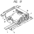
- Fig. 17 is a perspective view of the carrier 2 on which the head portion (recording head cartridge 1) shown in Fig. 3 is not mounted.
- a cable terminal portion 3a of the flexible cable 3 is provided at one end of the carrier 2.
- the cable terminal portion 3a is contacted with a head terminal portion 656 of each head portion (Figs. 18, 19 and 20) to electrical connection therebetween.
- Two head portion positioning projections 2a, 2b are integrally formed on a surface of the carrier 2 on which the cable terminal portion 3a is provided.
- the head portion positioning projection 2a is fitted in a positioning notch 657 of the head portion and the head portion positioning projection 2b is fitted in a positioning hole 658 of the head portion, thereby correctly positioning the head portion with respect to the carrier 2.
- a contact spring 28 is provided on the cable at a position opposed to the cable terminal portion 3a, and a resin-molded head guide 29 is mounted on a tip end of the contact spring. That is to say, the head guide 29 is elastically supported by the carrier 2.
- the head guide 29 is flexed, thereby permitting mounting and dismounting of the head portion, and the head guide serves to hold the head portion not to be disengaged upwardly.
- the head terminal portion 656 of the head portion is inserted into the cable terminal portion 3a of the carrier 2, and, by pushing the upper surface of the head portion downwardly, the head guide 29 is flexed, thereby completing the mounting of the head portion. In this case, the electrical connection is also completed.
- the head portion is dismounted, by pulling a head portion mounting and dismounting operation portion 51a, 53a or 200a upwardly by the operator's finger, the head guide 29 is flexed, thereby permitting the dismounting of the head portion.
- Fig. 18 is a perspective view of the monochromatic recording head 49 for effecting mono-color (normally, black) printing alone.
- a discharge opening surface 51b having nozzles for discharging recording ink is formed on a front side of a monochromatic recording head cartridge 51.
- the monochromatic recording head cartridge 51 has the head terminal portion 656 for receiving an electric signal.
- the electric signal is supplied from the recording apparatus portion (not shown) to the monochromatic recording head cartridge 51 through the head terminal portion 656, the ink is discharged from the nozzle provided in the discharge opening surface 51b downwardly (Fig. 18), thereby effecting the recording.
- the positioning notch 657 and the positioning hole 658 are provided for fitting onto the head portion positioning projections 2a, 2b provided on the carrier 2 to positively position the head portion with respect to the carrier 2.
- the ink is contained in a monochromatic ink tank 52.
- the monochromatic ink tank 52 is detachably fixed to the monochromatic recording head cartridge 51 by an elastic latch portion 52a integrally formed with the monochromatic ink tank 52.
- An ink flow passage defined by a detachable joint portion (not shown) is formed between the monochromatic ink tank 52 and the monochromatic recording head cartridge 51. Accordingly, when the ink is consumed by the recording and the ink in the monochromatic ink tank 52 is used up, the monochromatic ink tank 52 is removed from the monochromatic recording head cartridge 51 and a new monochromatic ink tank 52 is mounted to the monochromatic recording head cartridge 51. In this way, the recording can be continued.
- Fig. 19 is a perspective view of the color recording head portion 50 for effecting the color recording. Only the difference from the monochromatic recording head portion 49 will be described.
- Four kinds of independent nozzle groups (not shown) for discharging yellow color ink, magenta color ink, cyan color ink and black color ink to effect the color recording are provided in a discharge opening surface 653b of a color recording head cartridge 53.
- a black ink tank 54 contains the black ink therein and is connected to the nozzle group for black ink provided in the discharge opening surface 653b through a detachable joint portion (not shown).
- Interior of a color ink tank 55 is divided into three chambers within which the yellow ink, magenta ink and cyan ink are contained, respectively.
- the yellow ink chamber, magenta ink chamber and cyan ink chamber of the color ink tank 55 are connected to the nozzle group for yellow ink, nozzle group for magenta ink and nozzle group for cyan ink through three independent detachable joint portions (not shown).
- the black ink tank 54 has a latch portion 54a for exchange of the tank
- the color ink tank 55 has a latch portion 55a for exchange of the tank.
- the color recording head portion 50 by mounting the color recording head portion 50 to the recording apparatus portion 401, the color recording can be performed, and, when the black ink is used up, the black ink tank 54 alone can be exchanged, and, when one or all of the yellow ink, magenta ink and cyan ink are used up, the color ink tank 55 alone can be exchanged.
- Fig. 20 is a perspective view of the scanner head 200 which will be described later.
- "X” indicates a distance from the positioning notch 657 to the discharge opening surface 651b or 653b.
- the distance is selected to about 13 mm.
- "Y" indicates a distance from the positioning notch 657 to a reading surface 200b, which distance is set to be smaller than the distance X, and, in the illustrated embodiment, the distance Y is selected to about 9 mm.
- Figs. 21 and 22 are schematic sectional view and a perspective view showing the scanner head 200, respectively.
- LED light 207 emitted from an LED 206 for illuminating a surface 209 of an original is illuminated onto the original surface 209 through an LED opening 211.
- Image light 208 from the original surface 209 passes through a field lens 204 provided in a sensor opening 212 and is deflected at a right angle by a mirror 203 and passes through a focusing lens 201 to be focused on a sensor 202.
- the center of the sensor opening 212 is greater than a distance between the ink discharge opening 213 of the monochromatic recording cartridge 51 and the color recording cartridge 53 and the surface at which the recording head cartridge abuts against the carrier 2 for positioning, and, in the illustrated embodiment, it is deviated by about 4 mm.
- the LED 206 and the sensor 202 are electrically connected and are drawn outside through a wiring substrate 205.
- An electrode formed on a head terminal portion 256 of the wiring substrate 205 is contacted with an electrode (not shown) of the carrier 2 to direct a signal to a control circuit of the apparatus.
- the scanner head 200 has an outer configuration same as a configuration when the ink tank 8 is mounted to the recording head cartridge 1 and can be mounted to the carrier 2 by a latching action of a pawl 210 (a part of an outer wall), similar to the recording head cartridge 1.
- a pawl 210 a part of an outer wall
- an AISIC (CPU) 500 (Fig. 16) which will described later automatically discriminates the scanner to provide a scanner mode.
- a scanner reading signal is inputted to the AISIC 500 from a host computer, similar to a recording sheet 22, the original to be read is conveyed to a predetermined position by the sheet feeding motor 23. After the LED 206 is turned ON, the image signal is read through a scanner driver 513 while driving the carrier motor 10.
- the driving speed of the carrier motor 10 can be changed in dependence upon the original reading mode of the scanner head 200.
- the mode is a combination of a reading resolving power and gradation of read values. Since the resolving power of the scanner head 200 in the sheet supplying direction (main scan direction) is 360 dpi and the resolving power of the sensor 202 of the scanner head 200 in the scan direction of the carrier 2 (sub-scan direction) is 360 dpi, output having 64 gradations can be obtained.
- the scanner head 200 can perform the reading with 64 gradations including resolving powers of 360 dpi in the main scan direction and 360 dpi in the sub-scan direction through the reading with 2 gradations including resolving powers of 90 dpi in the main scan direction and 90 dpi in the sub-scan direction. Further, there is a mode in which the reading with the resolving power of 200 dpi in the main scan direction is effected in consideration of registration with a facsimile.
- the driving speed of the carrier is delayed; whereas, in the reading with 2 gradations including resolving powers of 90 dpi in the main scan direction and 90 dpi in the sub-scan direction, the driving speed of the carrier is increased.
- both the recording on the sheet 22 by using the recording head cartridge 1 and the reading of the original by using the scanner head 200 can be performed.
- the term “recording sheet” also includes the original, except for explanation regarding the recording alone.
- Fig. 16 shows an electrical block diagram of the recording apparatus.
- the reference numeral 500 denotes ASIC in which an MPU and a controller of the recording apparatus are integrally formed.
- the reference numeral 504 a flash ROM storing a program for controlling the entire recording apparatus;
- 505 denotes a mask ROM storing character fonts and the like;
- 506 denotes a DRAM used as a work area of the ASIC 500 and a signal buffer.
- the EEPROM 509 is constituted by re-writable ROM, so that the contents in the ROM is not erased even when the power is not supplied to the ROM.
- this EEPROM information regarding setting performed by the operator after the power source is turned ON, used ink amount and calculated disposal ink amount remaining in the recording apparatus and the like are stored.
- DC-DC converters 508 serve to convert voltage from an adaptor 507 into power source voltage used in the recording apparatus.
- the adaptor 507 is a transformer for converting domestic AC voltage of 100 V into DC voltage of 13 V.
- the recording apparatus includes a battery 116 therein for permitting the use of the apparatus outdoors. Further, since the recording apparatus includes a battery charge TC 510 therein, the apparatus can be re-charged without an additional charger.
- the reference numeral 502 denotes a carrier motor driver for driving the carrier 2; 503 denotes a sheet feeding motor driver for driving the sheet feeding roller 6.
- the carrier motor driver 502 and the sheet feeding motor driver 503 control the motors on the basis of control signals outputted from the AISIC 500.
- the reference numeral 106 denotes a power source switch for turning ON and OFF the power source; 108 denotes a head exchange switch for shifting the carrier 2 to an exchange position; 107 denotes an error cancel (release) switch; 110 denotes a power lamp; 109 denotes an error lamp; and 511 denotes a buzzer.
- Signal communication with respect to the external host computer is effected through an interface connector 118 and an infrared ray module 501.
- the interface connector is a wire connected to the host computer.
- the infrared ray module 501 is a serial communication port for infrared ray aligned with an infrared ray port of the host computer to effect infrared signal communication therebetween.
- an option connector 58 is prepared for effecting communication to an option ASF 127.
- the home position sensor 26 is of photo-interrupter type for detecting the position of the carrier 2 by sensing the edge of the carrier 2.
- the sheet sensor 25 and the discharge sheet sensor 17 are of contact type for detecting the presence/absence of the recording sheet in the recording apparatus.
- an openable tray also acting as a sheet discharge tray may be provided at the sheet discharge opening 122.
- the rigidity of the recording apparatus can be enhanced.
- the openable tray there may be provided an engagement portion directly engaged by the sheet supply opening or the sheet discharge opening 122. In this case, by inserting the engagement portion of the tray into the opening portion of the sheet supply path, the closed condition of the tray can be maintained.
- the recording system is not limited to the ink jet type, but, other type such as wire dot type or heat-transfer type may be used.
- the present invention is not limited to the recording apparatus, but, the present invention can be applied to image reading apparatuses or various sheet conveying apparatuses.
- the present invention provides a recording apparatus for recording an image on a sheet material, comprising an outer case having a box-shape, a convey path for conveying a sheet material within the outer case, a recording means disposed within the outer case and adapted to effect recording on the sheet material conveyed by the convey path, opening portions formed in the outer case to provide an inlet and an outlet of the convey path, and a lid member for closing at least one of the opening portions defining the inlet and said outlet, and wherein flexion of the outer case is reduced by closing the opening portion or portions by means of the lid member.
Landscapes
- Accessory Devices And Overall Control Thereof (AREA)
- Ink Jet (AREA)
- Delivering By Means Of Belts And Rollers (AREA)
Applications Claiming Priority (6)
| Application Number | Priority Date | Filing Date | Title |
|---|---|---|---|
| JP330875/97 | 1997-11-14 | ||
| JP33087597A JP3408128B2 (ja) | 1997-11-14 | 1997-11-14 | 記録装置 |
| JP33087597 | 1997-11-14 | ||
| JP12281598 | 1998-04-15 | ||
| JP122815/98 | 1998-04-15 | ||
| JP12281598A JPH11292340A (ja) | 1998-04-15 | 1998-04-15 | 記録装置 |
Publications (3)
| Publication Number | Publication Date |
|---|---|
| EP0916507A2 true EP0916507A2 (fr) | 1999-05-19 |
| EP0916507A3 EP0916507A3 (fr) | 1999-12-22 |
| EP0916507B1 EP0916507B1 (fr) | 2005-02-02 |
Family
ID=26459871
Family Applications (1)
| Application Number | Title | Priority Date | Filing Date |
|---|---|---|---|
| EP98121638A Expired - Lifetime EP0916507B1 (fr) | 1997-11-14 | 1998-11-12 | Imprimante |
Country Status (3)
| Country | Link |
|---|---|
| US (1) | US6382858B1 (fr) |
| EP (1) | EP0916507B1 (fr) |
| DE (1) | DE69828858T2 (fr) |
Families Citing this family (29)
| Publication number | Priority date | Publication date | Assignee | Title |
|---|---|---|---|---|
| JP3430025B2 (ja) * | 1998-07-30 | 2003-07-28 | シャープ株式会社 | ファクシミリ装置 |
| AUPP702498A0 (en) * | 1998-11-09 | 1998-12-03 | Silverbrook Research Pty Ltd | Image creation method and apparatus (ART77) |
| JP2002337415A (ja) * | 2001-03-15 | 2002-11-27 | Canon Inc | キャリッジを備える装置 |
| USD481753S1 (en) | 2002-01-07 | 2003-11-04 | Brother Industries, Limited | Printer with copying, scanning and facsimile functions with ink cartridge storage compartment |
| USD466924S1 (en) | 2002-01-30 | 2002-12-10 | Hewlett-Packard Company | Inkjet printer |
| TW571564B (en) * | 2002-07-22 | 2004-01-11 | Veutron Corp | Scanner |
| JP3913141B2 (ja) * | 2002-08-21 | 2007-05-09 | キヤノン株式会社 | 記録装置 |
| KR100461594B1 (ko) * | 2003-03-04 | 2004-12-18 | 삼성전자주식회사 | 전자사진방식 화상형성장치의 용지가이드 |
| USD516620S1 (en) * | 2004-01-15 | 2006-03-07 | Hewlett-Packard Development Company, L.P. | Printer |
| JP4186834B2 (ja) * | 2004-02-16 | 2008-11-26 | ソニー株式会社 | 液体吐出装置及びその制御方法 |
| USD518094S1 (en) * | 2004-02-18 | 2006-03-28 | Seiko Epson Corporation | Printer |
| US7222936B2 (en) * | 2004-05-11 | 2007-05-29 | Lexmark International, Inc. | Printhead carrier positioning apparatus and method |
| US7766438B2 (en) * | 2004-06-04 | 2010-08-03 | Lexmark International, Inc. | Method of ink evaporation prediction for an ink reservoir |
| USD534181S1 (en) * | 2005-04-22 | 2006-12-26 | Microsoft Corporation | Icon for a portion of a display screen |
| USD542794S1 (en) * | 2005-09-06 | 2007-05-15 | Lite-On Technology Corporation | Thin scanning and printing device |
| DE102006026706A1 (de) * | 2006-06-08 | 2007-12-13 | Siemens Ag | Fahrtschreiber für ein Kraftfahrzeug |
| USD563413S1 (en) * | 2006-07-05 | 2008-03-04 | Pfu Limited | Scanner |
| JP2009040044A (ja) * | 2007-07-17 | 2009-02-26 | Ricoh Co Ltd | 画像形成装置 |
| US20090321491A1 (en) * | 2008-06-06 | 2009-12-31 | Wick William R W | Edge Detection System |
| JP4806717B2 (ja) * | 2009-06-25 | 2011-11-02 | 株式会社沖データ | 画像処理システム |
| JP5479062B2 (ja) * | 2009-12-09 | 2014-04-23 | キヤノン株式会社 | 記録装置 |
| JP5783682B2 (ja) * | 2010-05-14 | 2015-09-24 | キヤノン株式会社 | 液体吐出ヘッドおよび液体吐出装置 |
| USD643039S1 (en) * | 2010-12-08 | 2011-08-09 | Hewlett-Packard Development Company, L.P. | Multi-function imaging and printing device |
| USD689867S1 (en) * | 2011-08-09 | 2013-09-17 | Canon Denshi Kabushiki Kaisha | Scanner |
| USD682834S1 (en) * | 2011-09-21 | 2013-05-21 | Canon Denshi Kabushiki Kaisha | Scanner |
| USD699726S1 (en) * | 2012-10-19 | 2014-02-18 | Brother Industries, Ltd. | Scanner |
| USD706269S1 (en) * | 2012-12-13 | 2014-06-03 | Hewlett-Packard Development Company, L.P. | Imaging device |
| JP6800612B2 (ja) * | 2016-05-26 | 2020-12-16 | キヤノン株式会社 | 液体吐出ヘッド及び液体吐出装置 |
| JP1598197S (fr) * | 2017-10-31 | 2019-02-18 |
Family Cites Families (15)
| Publication number | Priority date | Publication date | Assignee | Title |
|---|---|---|---|---|
| JPS54110009A (en) * | 1978-02-16 | 1979-08-29 | Suwa Seikosha Kk | Microprinter |
| JPS5747664A (en) * | 1980-09-05 | 1982-03-18 | Alps Electric Co Ltd | Serial printer |
| JPS57173188A (en) * | 1981-04-17 | 1982-10-25 | Alps Electric Co Ltd | Serial printer |
| US4623965A (en) * | 1984-02-27 | 1986-11-18 | Wing Donald K | Electronic checkbook |
| EP0268610B1 (fr) | 1986-04-24 | 1991-02-27 | EASTMAN KODAK COMPANY (a New Jersey corporation) | Modele d'imprimante permettant de recevoir une pluralite de formats de support d'impression |
| US5111244A (en) | 1987-10-30 | 1992-05-05 | Mita Industrial Co., Ltd. | Image-forming machine with improved process and optional unit assemblies |
| DE4008541C1 (fr) | 1990-03-16 | 1991-11-21 | Siemens Nixdorf Informationssysteme Ag, 4790 Paderborn, De | |
| JP2984066B2 (ja) * | 1991-01-29 | 1999-11-29 | 富士通アイソテック株式会社 | プリンタ用自動給紙装置 |
| JP2565527Y2 (ja) * | 1992-02-24 | 1998-03-18 | ブラザー工業株式会社 | プリンターの用紙挿入装置 |
| US5348407A (en) * | 1992-05-19 | 1994-09-20 | Hewlett-Packard Company | Snap-on control panel |
| ATE180719T1 (de) * | 1992-09-29 | 1999-06-15 | Canon Kk | Apparat zur papierversorgung |
| JP3197960B2 (ja) * | 1992-09-30 | 2001-08-13 | キヤノン株式会社 | 自動給送装置及び画像形成装置 |
| US5567068A (en) * | 1994-06-30 | 1996-10-22 | Matsushita Electric Industrial Co., Ltd. | Multifunction printer |
| JP3570034B2 (ja) * | 1995-08-31 | 2004-09-29 | ソニー株式会社 | プリンタ装置 |
| US6200043B1 (en) * | 1998-04-15 | 2001-03-13 | Canon Kabushiki Kaisha | Sheet feeding apparatus and image forming apparatus having such sheet feeding apparatus |
-
1998
- 1998-11-10 US US09/188,687 patent/US6382858B1/en not_active Expired - Lifetime
- 1998-11-12 EP EP98121638A patent/EP0916507B1/fr not_active Expired - Lifetime
- 1998-11-12 DE DE69828858T patent/DE69828858T2/de not_active Expired - Lifetime
Non-Patent Citations (1)
| Title |
|---|
| None |
Also Published As
| Publication number | Publication date |
|---|---|
| DE69828858D1 (de) | 2005-03-10 |
| US6382858B1 (en) | 2002-05-07 |
| EP0916507A3 (fr) | 1999-12-22 |
| EP0916507B1 (fr) | 2005-02-02 |
| DE69828858T2 (de) | 2006-01-12 |
Similar Documents
| Publication | Publication Date | Title |
|---|---|---|
| EP0916507B1 (fr) | Imprimante | |
| US6250827B1 (en) | Recording device and sheet material conveying device | |
| JP3733239B2 (ja) | 記録装置 | |
| US8425022B2 (en) | Ink container for ink jet printer, holder for the container, carriage for the holder, and ink jet printer | |
| US6997548B2 (en) | Tank holder, liquid tank and tank attaching and detaching method | |
| US20030035039A1 (en) | Ink jet recording apparatus | |
| US20060192804A1 (en) | Image forming apparatus | |
| AU773069B2 (en) | Ink container for ink jet printer, holder for the container carriage for the holder and ink jet printer | |
| JPH11300989A (ja) | インクジェット記録装置および廃インク量推計方法 | |
| US6076923A (en) | Recording apparatus | |
| JPH11300979A (ja) | 記録装置 | |
| JPH06344548A (ja) | インクジェット記録装置 | |
| JPH04141422A (ja) | 記録装置 | |
| JPH11301062A (ja) | 記録装置及び被記録材搬送装置 | |
| JPH11301080A (ja) | 記録装置およびロック機構 | |
| JPH11292341A (ja) | 記録装置 | |
| JPH11292346A (ja) | シート材検知装置およびシート材搬送装置および記録装置 | |
| JPH11301061A (ja) | 記録装置 | |
| JPH11292340A (ja) | 記録装置 | |
| JP2738777B2 (ja) | インクジェット記録装置 | |
| JP2828499B2 (ja) | インクジェット記録装置 | |
| JPH08282034A (ja) | インクジェット記録装置および該インクジェット記録装置が内蔵された情報処理装置 | |
| JPH0994945A (ja) | 記録装置 | |
| JPH04142943A (ja) | インク圧力検知装置およびインクジェット記録装置 |
Legal Events
| Date | Code | Title | Description |
|---|---|---|---|
| PUAI | Public reference made under article 153(3) epc to a published international application that has entered the european phase |
Free format text: ORIGINAL CODE: 0009012 |
|
| AK | Designated contracting states |
Kind code of ref document: A2 Designated state(s): DE FR GB IT |
|
| AX | Request for extension of the european patent |
Free format text: AL;LT;LV;MK;RO;SI |
|
| PUAL | Search report despatched |
Free format text: ORIGINAL CODE: 0009013 |
|
| AK | Designated contracting states |
Kind code of ref document: A3 Designated state(s): AT BE CH CY DE DK ES FI FR GB GR IE IT LI LU MC NL PT SE |
|
| AX | Request for extension of the european patent |
Free format text: AL;LT;LV;MK;RO;SI |
|
| 17P | Request for examination filed |
Effective date: 20000508 |
|
| AKX | Designation fees paid |
Free format text: DE FR GB IT |
|
| 17Q | First examination report despatched |
Effective date: 20030530 |
|
| GRAP | Despatch of communication of intention to grant a patent |
Free format text: ORIGINAL CODE: EPIDOSNIGR1 |
|
| RTI1 | Title (correction) |
Free format text: RECORDING APPARATUS |
|
| RTI1 | Title (correction) |
Free format text: RECORDING APPARATUS |
|
| GRAS | Grant fee paid |
Free format text: ORIGINAL CODE: EPIDOSNIGR3 |
|
| GRAA | (expected) grant |
Free format text: ORIGINAL CODE: 0009210 |
|
| AK | Designated contracting states |
Kind code of ref document: B1 Designated state(s): DE FR GB IT |
|
| REG | Reference to a national code |
Ref country code: GB Ref legal event code: FG4D |
|
| REF | Corresponds to: |
Ref document number: 69828858 Country of ref document: DE Date of ref document: 20050310 Kind code of ref document: P |
|
| PLBE | No opposition filed within time limit |
Free format text: ORIGINAL CODE: 0009261 |
|
| STAA | Information on the status of an ep patent application or granted ep patent |
Free format text: STATUS: NO OPPOSITION FILED WITHIN TIME LIMIT |
|
| ET | Fr: translation filed | ||
| 26N | No opposition filed |
Effective date: 20051103 |
|
| PGFP | Annual fee paid to national office [announced via postgrant information from national office to epo] |
Ref country code: FR Payment date: 20061108 Year of fee payment: 9 |
|
| PGFP | Annual fee paid to national office [announced via postgrant information from national office to epo] |
Ref country code: IT Payment date: 20061130 Year of fee payment: 9 |
|
| REG | Reference to a national code |
Ref country code: FR Ref legal event code: ST Effective date: 20080930 |
|
| PG25 | Lapsed in a contracting state [announced via postgrant information from national office to epo] |
Ref country code: FR Free format text: LAPSE BECAUSE OF NON-PAYMENT OF DUE FEES Effective date: 20071130 |
|
| PG25 | Lapsed in a contracting state [announced via postgrant information from national office to epo] |
Ref country code: IT Free format text: LAPSE BECAUSE OF NON-PAYMENT OF DUE FEES Effective date: 20071112 |
|
| PGFP | Annual fee paid to national office [announced via postgrant information from national office to epo] |
Ref country code: DE Payment date: 20151130 Year of fee payment: 18 Ref country code: GB Payment date: 20151125 Year of fee payment: 18 |
|
| REG | Reference to a national code |
Ref country code: DE Ref legal event code: R119 Ref document number: 69828858 Country of ref document: DE |
|
| GBPC | Gb: european patent ceased through non-payment of renewal fee |
Effective date: 20161112 |
|
| PG25 | Lapsed in a contracting state [announced via postgrant information from national office to epo] |
Ref country code: GB Free format text: LAPSE BECAUSE OF NON-PAYMENT OF DUE FEES Effective date: 20161112 Ref country code: DE Free format text: LAPSE BECAUSE OF NON-PAYMENT OF DUE FEES Effective date: 20170601 |