EP0916572A2 - Appareil étanche aux poussières et à l'eau pour un vraquier - Google Patents
Appareil étanche aux poussières et à l'eau pour un vraquier Download PDFInfo
- Publication number
- EP0916572A2 EP0916572A2 EP98309303A EP98309303A EP0916572A2 EP 0916572 A2 EP0916572 A2 EP 0916572A2 EP 98309303 A EP98309303 A EP 98309303A EP 98309303 A EP98309303 A EP 98309303A EP 0916572 A2 EP0916572 A2 EP 0916572A2
- Authority
- EP
- European Patent Office
- Prior art keywords
- walls
- frame member
- sensor unit
- roller
- sidewalls
- Prior art date
- Legal status (The legal status is an assumption and is not a legal conclusion. Google has not performed a legal analysis and makes no representation as to the accuracy of the status listed.)
- Withdrawn
Links
- XLYOFNOQVPJJNP-UHFFFAOYSA-N water Substances O XLYOFNOQVPJJNP-UHFFFAOYSA-N 0.000 title claims abstract description 24
- 239000000428 dust Substances 0.000 title claims abstract description 23
- 230000004913 activation Effects 0.000 description 2
- 238000003915 air pollution Methods 0.000 description 1
- 230000000295 complement effect Effects 0.000 description 1
- 238000007599 discharging Methods 0.000 description 1
Images


Classifications
-
- B—PERFORMING OPERATIONS; TRANSPORTING
- B63—SHIPS OR OTHER WATERBORNE VESSELS; RELATED EQUIPMENT
- B63B—SHIPS OR OTHER WATERBORNE VESSELS; EQUIPMENT FOR SHIPPING
- B63B17/00—Vessels parts, details, or accessories, not otherwise provided for
- B63B17/02—Awnings, including rigid weather protection structures, e.g. sunroofs; Tarpaulins; Accessories for awnings or tarpaulins
- B63B17/023—Hatchway tents, e.g. for weather protection of cargo during loading or unloading
Definitions
- This invention relates to a dust and water proof apparatus, more particularly to a dust and water proof apparatus for a bulk carrier.
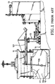
- Fig. 1 is a schematic plan view showing how powdery cargoes 10 are unloaded from a bulk carrier 11 at a quay 14.
- a generally vertical unloading rod member 120 of a conventional shore unloader 12 extends into a cargo hold 110 of the bulk carrier 11 via a cargo hatch 111 of the bulk carrier 11.
- the unloading rod member 120 is operable, for example, via a suction approach, so as to deliver the powdery cargoes 10 therealong to a generally horizontal transporting rod member 121.
- the transporting rod member 121 then delivers the powdery cargoes 10 to a silo room 13 at the quay 14 via other conveying equipment.
- the unloading operation since the dimension of the cargo hatch ill is relatively large, air pollution may result from a gust of wind during the unloading operation.
- the unloading operation must be temporarily stopped in the event of rainy weather, thereby increasing the costs incurred for the unloading operation.
- the object of the present invention is to provide a dust and water proof apparatus for a bulk carrier which can prevent powdery cargoes from becoming wet when unloading during rainy weather, and which can prevent the powdery cargoes from polluting the air during the unloading operation.
- a dust and water proof apparatus is adapted for use with a bulk carrier which has four hatch-defining walls that define a cargo hatch thereamong.
- the apparatus includes: a rectangular first frame member having two opposed sidewalls and two opposed end walls which interconnect the sidewalls, each of the sidewalls and the end walls being adapted to be located on a respective one of the hatch-defining walls, each of the sidewalls being formed with an elongated roller-receiving groove that extends longitudinally between the opposed end walls; a rectangular second frame member disposed among the sidewalls and the end walls of the first frame member, the second frame member having two opposed longer walls which are parallel to the end walls of the first frame member, and two opposed shorter walls which are parallel to the sidewalls of the first frame member, each of the shorter walls having at least two rollers which are mounted rotatably thereon and which extend into the roller-receiving groove of a corresponding one of the sidewalls of the first frame member so that the second frame member is movable relative to the first
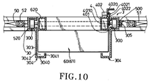
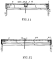
- a dust and water proof apparatus for a bulk carrier includes a rectangular first frame member 2, a rectangular second frame member 3, a rectangular third frame member 4, a first cover unit 5 and a second cover unit 6.
- the rectangular first frame member 2 has two opposed sidewalls 20 and two opposed end walls 21 which interconnect the sidewalls 20.
- each of the sidewalls 20 has an inner surface formed with an elongated roller-receiving groove 200 adjacent to the top of the sidewall 20.
- Each of the sidewalls 20 and end walls 21 of the first frame member 2 is adapted to be located on one of the hatch-defining walls 8 which define a cargo hatch 110 of a bulk carrier.
- a downwardly extending flange 201 is formed at the bottom of each of the sidewalls 20 and end walls 21 and abuts against the inner surface of the corresponding hatch-defining wall 8 so as to prevent relative movement between the first frame member 2 and the hatch-defining walls 8.
- Each of the sidewalls 20 further has an elongated groove-defining plate 202 which is provided on the inner surface thereof above the downwardly extending flange 201 and which extends longitudinally between the opposed end walls 21.
- the groove-defining plate 202 has a horizontal plate portion 2020 extending from the inner surface of the corresponding sidewall 20, and a vertical plate portion 2021 extending upwardly from the distal end of the horizontal plate portion 2020 so that a water-receiving groove 203 is formed among the inner surface of the sidewall 20, the horizontal plate portion 2020 and vertical plate portion 2021.
- the second frame member 3 is disposed among the sidewalls 20 and end walls 21 of the first frame member 2, and has two opposed longer walls 30 which are parallel to the end walls 21 of the first frame member 2, and two opposed shorter walls 31 which are parallel to the sidewalls 20 of the first frame member 2 and which interconnect the longer walls 30.
- At least two rollers 301 are mounted rotatably on an outer surface of each of the shorter walls 31 and extend rotatably into the roller-receiving groove 200 of a respective one of the sidewalls 20 of the first frame member 2 so that the second frame member 3 is movable relative to the first frame member 2 in a direction parallel to the sidewalls 20 of the first frame member 2.
- a bi-directional driving motor 302 is provided on the top of one of the shorter walls 31 of the second frame member 3.
- the driving motor 302 has a driving shaft 3020 on which a driving pulley 3021 is mounted.
- a driving belt 3022 interconnects the driving pulley 3021 and the axle 3010 of one of the rollers 301 so that activation of the driving shaft 3020 of the driving motor 302 to rotate in either a clockwise direction or a counter-clockwise direction results in corresponding rotation of said one of the rollers 301, thereby moving the second frame member 3 relative to the first frame member 2.
- Each of the longer walls 30 has an inner surface formed with an elongated roller-receiving groove 300, and a mounting plate 303 extending downwardly from the bottom thereof.
- An elongated groove-defining plate 304 is provided on an inner surface of the mounting plate 303 of each of the longer walls 30.
- the groove-defining plate 304 has a horizontal plate portion 3040 extending from the inner surface of the corresponding mounting plate 303, and a vertical plate portion 3041 extending upwardly from the distal end of the horizontal plate portion 3040 so that a water-receiving groove 3042 is formed among the horizontal plate portion 3040, the vertical plate portion 3041, and the inner surface of the mounting plate 303.
- the third frame member 4 is disposed among the longer and shorter walls 30,31 of the second frame member 3, and has two opposed roller-mounted walls 41 which are parallel to the longer walls 30 of the second frame member 3, and two opposed connecting walls 40 which are parallel to the shorter walls 31 of the second frame member 3 and which interconnect the roller-mounted walls 41.
- At least two rollers 401 are mounted rotatably on an outer surface of each of the roller-mounted walls 41 and extend into the roller-receiving groove 300 of a respective one of the longer walls 30 of the second frame member 3 so that the third frame member 4 is movable relative to the second frame member 3 in a direction parallel to the longer walls 30.
- a bi-directional driving motor 402 is provided on the top of one of the roller-mounted walls 41 of the third frame member 4.
- the driving motor 402 has a driving shaft 4020 on which a driving pulley 4021 is mounted.
- a driving belt 4022 interconnects the driving pulley 4021 and the axle 4010 of one of the rollers 401 so that activation of the driving shaft 4020 of the driving motor 402 to rotate in either a clockwise direction or a counter-clockwise direction result in corresponding rotation of said one of the rollers 401, thereby moving the third frame member 4 relative to the second frame member 3.
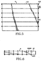
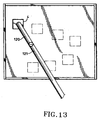
- a first sensor unit is connected electrically to the driving motor 302, and includes a signal transmitter (t1) which is mounted on one of the connecting walls 40 of the third frame member 4 adjacent to one of the roller-mounted walls 41 of the third frame member 4 and which generates continuously a sensing signal, and a signal receiver (r1) which is mounted on the other one of the connecting walls 40 of the third frame member 4 at a position opposite to the signal transmitter (t1) of the first sensor unit and which receives the sensing signal from the signal transmitter (t1) of the first sensor unit.
- the signal path between the signal transmitter (t1) and the signal receiver (r1) is indicated by a dotted line (a).
- the driving shaft 3020 of the driving motor 302 is activated to rotate in a clockwise direction when reception of the sensing signal from the signal transmitter (t1) of the first sensor unit by the signal receiver (r1) of the same is interrupted.
- a second sensor unit is also connected electrically to the driving motor 302.
- the second sensor unit includes a signal transmitter (t2) which is mounted on the same connecting wall 40 as the signal transmitter (t1) adjacent to the other one of the roller-mounted walls 41 of the third frame member 4 and which generates continuously a sensing signal, and a signal receiver (r2) which is mounted on the same connecting wall 40 as the signal receiver (r1) at a position opposite to the signal transmitter (t2) of the second sensor unit and which receives the sensing signal from the signal transmitter (t2) of the second sensor unit.
- the signal path between the signal transmitter (t2) and the signal receiver (r2) is indicated by a dotted line (b).
- the driving shaft 3020 of the driving motor 302 is activated to rotate in a counter-clockwise direction when reception of the sensing signal from the signal transmitter (t2) of the second sensor unit by the signal receiver (r2) of the same is interrupted.
- a third sensor unit is connected electrically to the driving motor 402.
- the third sensor unit includes a signal transmitter (t3) which is mounted on one of the roller-mounted walls 41 of the third frame member 4 adjacent to one of the connecting walls 40 of the third frame member 4 and which generates continuously a sensing signal., and a signal receiver (r3) which is mounted on the other one of the roller-mounted walls 41 of the third frame member 4 at a position opposite to the signal transmitter (t3) of the third sensor unit and which receives the sensing signal from the signal transmitter (t3) of the third sensor unit.
- the signal path between the signal transmitter (t3) and the signal receiver (r3) is indicated by a dotted line (c).
- the driving shaft 4020 of the driving motor 402 is activated to rotate in a clockwise direction when reception of the sensing signal from the signal transmitter (t3) of the third sensor unit by the signal receiver (r3) of the same is interrupted.
- a fourth sensor unit is also connected electrically to the driving motor 402.
- the second sensor unit includes a signal transmitter (t4) which is mounted on the same roller-mounted wall 41 as the signal transmitter (t3) adjacent to the other one of the connecting walls 40 of the third frame member 4 and which generates continuously a sensing signal, and a signal receiver (r4) which is mounted on the same roller-mounted wall 41 as the signal receiver (r3) at a position opposite to the signal transmitter (t4) of the fourth sensor unit and which receives the sensing signal from the signal transmitter (t4) of the fourth sensor unit.
- the signal path between the signal transmitter (t4) and the signal receiver (r4) is indicated by a dotted line (d).
- the driving shaft 4020 of the driving motor 402 is activated to rotate in a counter-clockwise direction when reception of the sensing signal from the signal transmitter (t4) of the fourth sensor unit by the signal receiver (r4) of the same is interrupted.
- the first cover unit includes a flexible first canopy 50 which is disposed among the sidewalls 20 of the first frame member 2, one of the longer walls 30 of the second frame member 3 and one of the end walls 21 of the first frame member 2, and a flexible second canopy 51 which is disposed among the sidewalls 20 of the first frame member 2, the other one of the longer walls 30 of the second frame member 3 and the other one of the end walls 21 of the first frame member 2.
- Each of the first and second canopies 50,51 of the first cover unit 5 has a first end portion connected to the corresponding end wall 21 of the first frame member 2, and a second end portion connected to the corresponding longer wall 30 of the second frame member 3.
- the second end portion of the first canopy 50 of the first cover unit 5 is provided with a hook member 500 which is connected detachably to a complementary hook member 305 formed on the corresponding longer wall 30 of the second frame member 3.
- Each of the canopies 50,51 of the first cover unit 5 further has a plurality of equidistant rods 52 which are fixed thereto, such as by stitching, and which have opposite ends extending out of two sides of the canopy 50,51.
- Each of the rods 52 has a roller 520 which is mounted rotatably to each of the opposite ends thereof and which extends rotatably into the roller-receiving groove 200 of the first frame member 2.
- the second cover unit 6 includes a flexible first canopy 60 which is disposed among the longer walls 30 of the second frame member 3, one of the shorter walls 31 of the second frame member 3 and one of the connecting walls 40 of the third frame member 4, and a flexible second canopy 61 which is disposed among the longer walls 30 of the second frame member 3, the other one of the shorter walls 31 of the second frame member 3 and the other one of the connecting walls 40 of the third frame member 4.
- Each of the first and second canopies 60,61 of the second cover unit 6 has a first end portion connected to the corresponding shorter wall 31 of the second frame member 3, and a second end portion connected to the corresponding connecting wall 40 of the third frame member 4.
- Each of the canopies 60,61 of the second cover unit 6 further has a plurality of equidistant rods 62 which are fixed thereto, for example, by stitching and which have opposite ends extending out of two sides of the canopy 60,61.
- Each of the rods 62 has a roller 620 which is mounted rotatably to each of the opposite ends thereof and which extends rotatably into the roller-receiving groove 300 of the second frame member 3.
- a generally vertical unloading rod member 120 of a shore unloader extends into the cargo hold 110 of the bulk carrier via the third frame member 4, and is operated to deliver the powdery cargoes (not shown) therealong.
- the rod member 120 can be driven to move so as to unload the powdery cargoes in every position of the cargo hold 110.
- the driving shaft 3020,4020 of the corresponding driving motor 302,402 is activated to rotate in the clockwise direction or in the counterclockwise direction, depending on which signal path (a), (b), (c), (d) is blocked, thereby resulting in movement of a corresponding one of the second and third frame members 3 and 4 in order to prevent collision of the rod member 120 with the walls 40,41 of the third frame member 4.
- the driving shaft 3020 of the driving motor 302 is activated to rotate in a clockwise direction so as to move the second frame member 3 relative to the first frame member 2.
- the rod member 120 of the shore unloader is able to extend to any position of the cargo hold 110 without being blocked by the third frame member 4.
- water dropping out of the canopies 50,51 and 60,61 of the first and second cover units 5 and 6 via the two sides of the canopies 50,51 and 60,61 of the first and second cover units 5 and 6 can be received in the water-receiving groove 203,3042 and discharged through a discharging hole (not shown).
Landscapes
- Chemical & Material Sciences (AREA)
- Engineering & Computer Science (AREA)
- Combustion & Propulsion (AREA)
- Mechanical Engineering (AREA)
- Ocean & Marine Engineering (AREA)
- Rollers For Roller Conveyors For Transfer (AREA)
- Casings For Electric Apparatus (AREA)
- Prevention Of Fouling (AREA)
- Refuse-Collection Vehicles (AREA)
Applications Claiming Priority (2)
| Application Number | Priority Date | Filing Date | Title |
|---|---|---|---|
| US08/970,705 US5813815A (en) | 1997-11-14 | 1997-11-14 | Dust and water proof apparatus for bulk carrier |
| US970705 | 1997-11-14 |
Publications (2)
| Publication Number | Publication Date |
|---|---|
| EP0916572A2 true EP0916572A2 (fr) | 1999-05-19 |
| EP0916572A3 EP0916572A3 (fr) | 2001-09-05 |
Family
ID=25517367
Family Applications (1)
| Application Number | Title | Priority Date | Filing Date |
|---|---|---|---|
| EP98309303A Withdrawn EP0916572A3 (fr) | 1997-11-14 | 1998-11-13 | Appareil étanche aux poussières et à l'eau pour un vraquier |
Country Status (3)
| Country | Link |
|---|---|
| US (1) | US5813815A (fr) |
| EP (1) | EP0916572A3 (fr) |
| CN (1) | CN1219494A (fr) |
Cited By (5)
| Publication number | Priority date | Publication date | Assignee | Title |
|---|---|---|---|---|
| WO2019240129A1 (fr) * | 2018-06-15 | 2019-12-19 | Ihi運搬機械株式会社 | Appareil de protection contre la pluie pour la navigation |
| WO2021049051A1 (fr) * | 2019-09-11 | 2021-03-18 | 三菱重工業株式会社 | Turbine à gaz |
| JP6849865B1 (ja) * | 2019-09-24 | 2021-03-31 | Ihi運搬機械株式会社 | 船積み用雨除け装置 |
| JP2021049831A (ja) * | 2019-09-24 | 2021-04-01 | Ihi運搬機械株式会社 | 船積み用防風雨装置 |
| WO2021059546A1 (fr) * | 2019-09-24 | 2021-04-01 | Ihi運搬機械株式会社 | Dispositif de protection contre la pluie pour l'expédition |
Families Citing this family (4)
| Publication number | Priority date | Publication date | Assignee | Title |
|---|---|---|---|---|
| JP3389459B2 (ja) | 1997-07-10 | 2003-03-24 | 新日本製鐵株式会社 | 全天候型荷役岸壁設備および該設備を用いた荷役の積み下ろし方法 |
| US6058557A (en) * | 1998-01-30 | 2000-05-09 | Holnam, Inc. | Fugitive dust collector |
| WO2005003543A1 (fr) * | 2003-07-02 | 2005-01-13 | Tiax Llc | Regulation de moteur stirling a piston libre |
| CN115923996B (zh) * | 2022-12-07 | 2023-10-31 | 江苏尚源船艇制造有限公司 | 一种用于游艇制造的分区调节式遮阳装置 |
Family Cites Families (8)
| Publication number | Priority date | Publication date | Assignee | Title |
|---|---|---|---|---|
| US2843273A (en) * | 1955-11-25 | 1958-07-15 | Olof J Sanden | Rain protecting device, especially for hatchways on ships |
| US3348705A (en) * | 1965-07-02 | 1967-10-24 | Harold H Yanow | Weather tent for cargo hatches |
| US4237809A (en) * | 1979-03-02 | 1980-12-09 | The Ohio River Company | Cover for a barge |
| DE3225349A1 (de) * | 1982-07-07 | 1984-01-12 | Kali-Transportgesellschaft m.b.H., 2000 Hamburg | Wetter- und staubabdeckung fuer luken |
| GB2234204B (en) * | 1989-07-20 | 1993-01-20 | Per Tybring Aralt | Arrangements for unloading bulk material from holds of cargo vessels |
| US5322405A (en) * | 1991-10-30 | 1994-06-21 | Pacific Coast Cement Corporation | Dust control system |
| NO175576C (no) * | 1992-07-15 | 1994-11-02 | Norsk Hydro As | Beskyttelsesanordning for lager- eller lasterom |
| DE19519283C1 (de) * | 1995-05-22 | 1996-11-07 | Mannesmann Ag | Ladeschacht zum Abdecken einer Schiffsluke oder ähnlichen Ladeöffnung während des Be- und Entladevorganges |
-
1997
- 1997-11-14 US US08/970,705 patent/US5813815A/en not_active Expired - Fee Related
-
1998
- 1998-11-12 CN CN98122458A patent/CN1219494A/zh active Pending
- 1998-11-13 EP EP98309303A patent/EP0916572A3/fr not_active Withdrawn
Non-Patent Citations (1)
| Title |
|---|
| None |
Cited By (9)
| Publication number | Priority date | Publication date | Assignee | Title |
|---|---|---|---|---|
| WO2019240129A1 (fr) * | 2018-06-15 | 2019-12-19 | Ihi運搬機械株式会社 | Appareil de protection contre la pluie pour la navigation |
| JPWO2019240129A1 (ja) * | 2018-06-15 | 2020-07-02 | Ihi運搬機械株式会社 | 船積み用雨除け装置 |
| US11505284B2 (en) | 2018-06-15 | 2022-11-22 | Transport Machinery Co., Ltd. | Rain-guard device for shipping |
| WO2021049051A1 (fr) * | 2019-09-11 | 2021-03-18 | 三菱重工業株式会社 | Turbine à gaz |
| JP6849865B1 (ja) * | 2019-09-24 | 2021-03-31 | Ihi運搬機械株式会社 | 船積み用雨除け装置 |
| JP2021049831A (ja) * | 2019-09-24 | 2021-04-01 | Ihi運搬機械株式会社 | 船積み用防風雨装置 |
| WO2021059546A1 (fr) * | 2019-09-24 | 2021-04-01 | Ihi運搬機械株式会社 | Dispositif de protection contre la pluie pour l'expédition |
| JP7015814B2 (ja) | 2019-09-24 | 2022-02-03 | Ihi運搬機械株式会社 | 船積み用防風雨装置 |
| US11577921B2 (en) | 2019-09-24 | 2023-02-14 | Ihi Transport Machinery Co., Ltd. | Rain-guard device for shipping |
Also Published As
| Publication number | Publication date |
|---|---|
| CN1219494A (zh) | 1999-06-16 |
| US5813815A (en) | 1998-09-29 |
| EP0916572A3 (fr) | 2001-09-05 |
Similar Documents
| Publication | Publication Date | Title |
|---|---|---|
| US5813815A (en) | Dust and water proof apparatus for bulk carrier | |
| US12089537B2 (en) | Track driven sweep system for grain bins | |
| KR101686237B1 (ko) | 하역매트의 경사면 형성을 이용한 적재물 하역 장치 | |
| EP0000550A1 (fr) | Transporteur élévateur pour matériau en vrac et système de délivrance appliquant les caractéristiques de celui-ci | |
| US4266902A (en) | Transport container | |
| EP1505012A3 (fr) | Système de déchargement de matières en vrac avec convoyeurs au sol à mouvement alternatif | |
| CN117023199A (zh) | 多型式输送系统接续搬运的连续卸船机及其工作方法 | |
| JPS6323091B2 (fr) | ||
| JPS62265092A (ja) | 粉粒物の輸送船 | |
| KR200468113Y1 (ko) | 하부배출구가 형성된 곡물 적재함 | |
| JP3211761B2 (ja) | ばら物用アンローダ | |
| JP2001247212A (ja) | 開閉可能なカバーを有するチェーンコンベヤー | |
| GB2029352A (en) | Endless Conveyor System | |
| US3977540A (en) | Marine unloading and loading system of powdered and lumpy bulk materials for holds with a pneumatic discharge device | |
| CN117228276A (zh) | 双向皮带机自动转换向卸料斗 | |
| KR102846505B1 (ko) | 적재물을 수평 방향으로 하역시키기 위한 차량 적재함 | |
| CN216511628U (zh) | 一种矿用翻转卸料装置 | |
| HK40074950A (en) | Handling method | |
| JPH0415708Y2 (fr) | ||
| KR0162279B1 (ko) | 스크류형 집진수단을 갖는 연속식 언로더 | |
| CN114988149A (zh) | 装卸方法 | |
| US7004707B2 (en) | Movable bulk charging/discharging equipment | |
| JPH0734042Y2 (ja) | 嵩物の陸揚・船積兼用機 | |
| JPH05278675A (ja) | ばら積船 | |
| KR960000737A (ko) | 이동식 벌크 시멘트 하역 및 출하 장치 |
Legal Events
| Date | Code | Title | Description |
|---|---|---|---|
| PUAI | Public reference made under article 153(3) epc to a published international application that has entered the european phase |
Free format text: ORIGINAL CODE: 0009012 |
|
| AK | Designated contracting states |
Kind code of ref document: A2 Designated state(s): AT BE CH CY DE DK ES FI FR GB GR IE IT LI LU MC NL PT SE |
|
| AX | Request for extension of the european patent |
Free format text: AL;LT;LV;MK;RO;SI |
|
| PUAL | Search report despatched |
Free format text: ORIGINAL CODE: 0009013 |
|
| AK | Designated contracting states |
Kind code of ref document: A3 Designated state(s): AT BE CH CY DE DK ES FI FR GB GR IE IT LI LU MC NL PT SE |
|
| AX | Request for extension of the european patent |
Free format text: AL;LT;LV;MK;RO;SI |
|
| RIC1 | Information provided on ipc code assigned before grant |
Free format text: 7B 63B 19/14 A, 7B 63B 19/28 B, 7B 63B 17/02 B, 7B 63B 19/18 B |
|
| STAA | Information on the status of an ep patent application or granted ep patent |
Free format text: STATUS: THE APPLICATION IS DEEMED TO BE WITHDRAWN |
|
| 18D | Application deemed to be withdrawn |
Effective date: 20010601 |