EP0916758A2 - Halblitze einer Drehkantenvorrichtung mit Hebelitze - Google Patents
Halblitze einer Drehkantenvorrichtung mit Hebelitze Download PDFInfo
- Publication number
- EP0916758A2 EP0916758A2 EP98121055A EP98121055A EP0916758A2 EP 0916758 A2 EP0916758 A2 EP 0916758A2 EP 98121055 A EP98121055 A EP 98121055A EP 98121055 A EP98121055 A EP 98121055A EP 0916758 A2 EP0916758 A2 EP 0916758A2
- Authority
- EP
- European Patent Office
- Prior art keywords
- foot
- lifting
- strands
- heald
- strand according
- Prior art date
- Legal status (The legal status is an assumption and is not a legal conclusion. Google has not performed a legal analysis and makes no representation as to the accuracy of the status listed.)
- Granted
Links
Images

Classifications
-
- D—TEXTILES; PAPER
- D03—WEAVING
- D03C—SHEDDING MECHANISMS; PATTERN CARDS OR CHAINS; PUNCHING OF CARDS; DESIGNING PATTERNS
- D03C7/00—Leno or similar shedding mechanisms
- D03C7/02—Gauze healds
Definitions
- Half heald of a leno edge device with lifting healds the half heald has two legs, which at their upper end to form one Head are connectable, and one foot each at its lower end have, the foot with the at least one magnet Lifting wire works together magnetically.
- a leno selvedge device of the type mentioned is known from DE-PS 38 18 680 well known.
- the device for forming a The leno edge consists of two lifting healds, the two alternately moving heald frames of a loom are arranged.
- the A device for forming a leno edge also comprises a Half strands, which from the lifting strands according to the movement of the Heald frames are taken alternately.
- the half strand has two thighs that form at their top end forming a head converge with an eyelet to guide the upright thread.
- Such Half strand is made of metallic material.
- Each lifting wire has their lower end has at least one magnet that is controlled Carrying the half strand through the respective lifting strands in such a way that it is ensured by the magnetic force that the half strands of the lifting strands during the respective entraining movement by the lifting strands is held.
- this principle is from DE-PS 38 18 680 well known.
- the half strand is carried by the Lifting wire and here in particular by one arranged in the lifting wire Bridge on which the half strand with its end head during the Carried by the respective lifting heald.
- the invention is therefore based on the object, a half strand of the input to create the type mentioned, which increases the lifespan of the lifting healds also possible with very fast weaving machines.
- the foot of the Half heddle has a shape such that that on the foot of the half heddle Magnetic force acting in the stroke direction of the lifting strands is smaller than in the opposite direction, with the foot in the form of an upper end has a trailing edge, so that the semi-strands through the lifting strands is mutually magnetically braked.
- the magnetic resistance against a Submerge the half strands against the lifting direction of the lifting strands so far is increased that it is ultimately greater than the resistance to the Lifting the foot of the half strands out of the magnetic field is required.
- the result of this is that during this movement the half strands no longer enter the a lifting brace dips and onto the web of one lifting brace - like this is the case with the prior art - comes to rest. That is, it finds consequently there is no more wear on the web of the lifting heald, so that in principle this bridge can also be dispensed with.
- the means that such a leno edge device comprising two Lever strands and a half strand work essentially without wear.
- the foot of the half strands tapers downward, ie counter to the lifting direction.
- the type of taper can be done either in cross-section or in a top view of the foot of the leg of the lifting heald.
- the shape of the foot advantageously shows the shape of a triangle, the downward tip of which points to the center of the magnet of the lifting heald. Upwards, that is, as the upper end, the foot has the end edge.
- the Legs cranked in the lower area to accommodate the foot is. This ensures that the foot upwards, d. H. in the stroke direction can form a free trailing edge with that already described above Consequence that the corresponding magnetic through this terminating edge Resistance to submerging the half strands against the stroke direction the leverage is increased so that it is ultimately larger than the Resistance used to lift the half strands out of the magnetic field is required.
- leg is cranked outwards is trained. This means that the bow created by the cranking after shows outside. Such training is advantageous to the extent that in Area of the lifting heald is more space available.
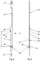
- the device 1 for forming a leno edge comprises two lifting healds 2, 3, which can be connected to reciprocating heald frames, and the take the half strands 50 mutually accordingly.
- the principle of operation is known, for example, from DE-PS 38 18 680 which is hereby expressly referred to.
- Each lifting heald 2, 3 consists of essentially of two legs 10, 20, each of these legs 10, 20 a hook-shaped element 11 or 21 for attachment to the heddle support rails (not shown) of the corresponding alternately moved Has heald frames of the loom.
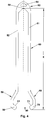
- the half-heddle 50 shown in FIG. 4 shows two legs 51, 52 at its upper end to form a head 53 converge.
- the head 53 shows an eyelet 54 for receiving the through the half-strand 50 guided thread.
- the legs 51, 52 are on hers lower end each cranked to form a foot 70, 80 educated.
- the offset (arrow 55, 56) is chosen such that these each form an arc outwards so that these feet 70, 80 point inwards.
- the feet 70, 80 are designed such that taper them downwards (arrow 90), but taper them upwards Form end edge 71, 81.
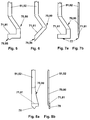
- Other embodiments of the foot can be found in FIGS. 5 to 8.
- the leg 20 of the lifting heald 2, 3 shows a slot 22 for slidably receiving the leg 51, 52 of the half-heddle 50 (Figure 3).
- a guide opening 30 provided the entrance to the slot 22 of the leg 20 for the Legs 51, 52 of the half heddle 50 represents. It follows that the thigh 20 in principle, forming the slot 22 from two walls 25, 26 exists, which on a long side of the slot to form the web 23rd are held together.
- each leg 20 Magnet pair 40 Such a magnet pair 40 consists of two magnets 41, 42, which are opposite each other in the walls 25, 26 of Leg 20 of the lifting heald 2, 3 are arranged. It is now essential that the length X of the leg 51, 52 of the half strand 50 is greater than that Distance Y from the magnet pair 40 to the upper end 24 of the web 23 ( Figure 2). Because this ensures that the semi-heddle 50 with their Head 53 and here in particular with the roof-shaped connecting web 59 no longer comes to rest on the end 24.
- a tip 76, 86 is shown, which also enables a continuous increase in material.
- FIGS. 8a, 8b differs from that other embodiments than here the leg of the half strand from not magnetic material is formed, the tip 78, however, from magnetic material.
- the end edge 71, 81 is thus by the Transition from non-magnetic to magnetic material.
Landscapes
- Engineering & Computer Science (AREA)
- Textile Engineering (AREA)
- Looms (AREA)
Abstract
Description
da durch die Verjüngung des Fußes der Widerstand kontinuierlich abnimmt, wohingehend der Widerstand zum Überwinden der Abschlußkante zwar abrupt abnimmt, aber dennoch aufgrund des abrupten Übergangs wesentlich höher ist.
- Figur 1
- zeigt die vollständige Vorrichtung zum Bilden einer Dreherkante mit zwei Hebelitzen und einer Halblitze;
- Figur 2
- zeigt eine Hebelitze in einer Seitenansicht;
- Figur 3
- zeigt die Hebelitze gemäß Figur 2 in einer Ansicht gemäß dem Pfeil III aus Figur 2;
- Figur 4
- zeigt die Halblitze in vergrößerter Darstellung.
- Figur 5 bis Figur 8
- zeigen verschiedene Ausführungsformen des Fußes des Schenkels einer Halblitze.
Claims (8)
- Halblitze einer Dreherkantenvorrichtung mit Hebelitzen, wobei die Halblitze zwei Schenkel aufweist, die an ihrem oberen Ende unter Bildung eines Kopfes verbindbar sind, und die an ihrem unteren Ende jeweils einen Fuß aufweisen, wobei der Fuß mit mindestens einem Magneten der Hebelitze magnetisch zusammenarbeitet,
dadurch gekennzeichnet,
daß der Fuß (70, 80) der Halblitze (50) eine Form derart aufweist, dass die auf den Fuß (70, 80) der Halblitze (50) wirkende Magnetkraft in Hubrichtung (Pfeil 100) der Hebelitzen (2, 3) kleiner ist, als in der entgegengesetzten Richtung, wobei der Fuß (70, 80) einen oberen Abschluß in Form einer Abschlußkante (71, 81) aufweist, so daß die Halblitze (59) durch die Hebelitzen (2, 3) wechselseitig magnetisch abbremsbar ist. - Halblitze nach Anspruch 1,
dadurch gekennzeichnet,
daß sich der Fuß (70, 80) nach unten hin verjüngt. - Halblitze nach Anspruch 2,
dadurch gekennzeichnet,
daß sich der Fuß (70, 80) nach unten hin im Querschnitt verjüngt. - Halblitze nach Anspruch 2,
dadurch gekennzeichnet,
daß sich der Fuß (70, 80) nach unten hin in der Ansicht verjüngt. - Halblitze nach Anspruch 1,
dadurch gekennzeichnet,
daß der Schenkel (51, 52) im unteren Bereich zur Aufnahme des Fußes (70, 80) gekröpft ausgebildet ist. - Halblitze nach Anspruch 1,
dadurch gekennzeichnet,
daß der Schenkel (51, 52) nach außen gekröpft ausgebildet ist. - Halblitze nach Anspruch 1,
dadurch gekennzeichnet,
daß die Abschlußkante (71, 81) sich im wesentlichen über die Breite des Magneten (41, 42) der Hebelitze (2, 3) erstreckt. - Halblitze nach Anspruch 2,
dadurch gekennzeichnet,
daß der Fuß (70,80) etwa nach Art eines Dreiecks ausgebildet ist, wobei die nach unten gerichtete Spitze des Dreiecks auf die Mitte des Magneten (41,42) gerichtet ist.
Applications Claiming Priority (2)
| Application Number | Priority Date | Filing Date | Title |
|---|---|---|---|
| DE19750804 | 1997-11-17 | ||
| DE19750804A DE19750804C1 (de) | 1997-11-17 | 1997-11-17 | Halblitze einer Dreherkantenvorrichtung mit Hebelitzen |
Publications (3)
| Publication Number | Publication Date |
|---|---|
| EP0916758A2 true EP0916758A2 (de) | 1999-05-19 |
| EP0916758A3 EP0916758A3 (de) | 1999-07-07 |
| EP0916758B1 EP0916758B1 (de) | 2002-07-10 |
Family
ID=7848926
Family Applications (1)
| Application Number | Title | Priority Date | Filing Date |
|---|---|---|---|
| EP98121055A Expired - Lifetime EP0916758B1 (de) | 1997-11-17 | 1998-11-06 | Drehkantenvorrichtung mit Hebelitzen und Halblitze |
Country Status (4)
| Country | Link |
|---|---|
| US (1) | US6116291A (de) |
| EP (1) | EP0916758B1 (de) |
| JP (1) | JP4039478B2 (de) |
| DE (2) | DE19750804C1 (de) |
Cited By (1)
| Publication number | Priority date | Publication date | Assignee | Title |
|---|---|---|---|---|
| US6116291A (en) * | 1997-11-17 | 2000-09-12 | Klocker-Etwicklungs Gmbh | Half heald of a leno selvedge device with lifting healds |
Families Citing this family (12)
| Publication number | Priority date | Publication date | Assignee | Title |
|---|---|---|---|---|
| DE10004376A1 (de) * | 2000-02-02 | 2001-08-23 | Dornier Gmbh Lindauer | Verfahren zum Herstellen eines Dreher-Grundgewebes auf Webmaschinen |
| US6851456B2 (en) * | 2001-07-18 | 2005-02-08 | Sultzer Textil Ag | Weaving machine for the manufacture of leno cloths |
| DE10257519B3 (de) * | 2002-12-10 | 2004-04-01 | Klöcker-Entwicklungs-Gmbh | Vorrichtung zum Bilden einer Dreherkante |
| US7131465B1 (en) * | 2004-06-24 | 2006-11-07 | Chapman Arthur S | Removable plastic heddle with mating insertion tool for weaving apparatus |
| WO2006069562A1 (de) | 2004-12-31 | 2006-07-06 | Lindauer Dornier Gesellschaft Mbh | Drehergewebe sowie verfahren und webmaschine zu dessen herstellung |
| BE1016891A6 (nl) * | 2005-12-13 | 2007-09-04 | Picanol Nv | Broekhevelinrichting voor een weefmachine. |
| PT2063007E (pt) * | 2007-11-21 | 2010-12-22 | Groz Beckert Kg | Dispositivo para fabrico de gazes |
| JP5188944B2 (ja) * | 2008-12-08 | 2013-04-24 | 株式会社豊田自動織機 | 綜絖枠 |
| US8944116B2 (en) * | 2013-03-07 | 2015-02-03 | Rome Division Rummel Fibre Co., Inc. | Leno heddle |
| EP3162934B1 (de) * | 2015-10-28 | 2018-03-28 | Gebrüder Klöcker GmbH | Vorrichtung zum bilden einer dreherkante, insbesondere für eine webmaschine sowie projektilwebmaschine mit einer solchen vorrichtung |
| DE202018107373U1 (de) * | 2018-12-21 | 2019-01-29 | Gebrüder Klöcker GmbH | Vorrichtung zum Bilden einer Dreherkante |
| DE102024115051B3 (de) | 2024-05-29 | 2025-06-18 | Gebrüder Klöcker GmbH | Dreherkantenvorrichtung zur bildung einer dreherkante |
Family Cites Families (7)
| Publication number | Priority date | Publication date | Assignee | Title |
|---|---|---|---|---|
| DE8703920U1 (de) * | 1987-03-16 | 1988-07-21 | Klöcker-Entwicklungs-GmbH, 4280 Borken | Zur Erzielung einer Dreherkante geeigneter Webschaft |
| DE3818680C5 (de) * | 1988-06-01 | 2006-06-22 | Klöcker-Entwicklungs-Gmbh | Vorrichtung zum Bilden einer Dreherkante |
| DE3830107A1 (de) * | 1988-09-05 | 1990-04-12 | Egelhaaf C C Fa | Drehervorrichtung fuer webmaschinen |
| DE8814891U1 (de) * | 1988-11-30 | 1989-03-09 | Klöcker-Entwicklungs-GmbH, 4280 Borken | Vorrichtung zum Bilden einer Dreherkante, insbesondere zum Einsatz auf einer Jacquard-Maschine |
| DE8903775U1 (de) * | 1989-03-25 | 1989-07-13 | Klöcker-Entwicklungs-GmbH, 4280 Borken | Halblitze zur Führung eines Dreherfadens |
| DE3912733C1 (de) * | 1989-04-19 | 1990-07-26 | Kloecker-Entwicklungs-Gmbh, 4280 Borken, De | |
| DE19750804C1 (de) * | 1997-11-17 | 1999-05-12 | Kloecker Entwicklungs Gmbh | Halblitze einer Dreherkantenvorrichtung mit Hebelitzen |
-
1997
- 1997-11-17 DE DE19750804A patent/DE19750804C1/de not_active Expired - Fee Related
-
1998
- 1998-11-06 EP EP98121055A patent/EP0916758B1/de not_active Expired - Lifetime
- 1998-11-06 DE DE59804716T patent/DE59804716D1/de not_active Expired - Lifetime
- 1998-11-16 JP JP36180398A patent/JP4039478B2/ja not_active Expired - Fee Related
- 1998-11-16 US US09/193,168 patent/US6116291A/en not_active Expired - Lifetime
Cited By (1)
| Publication number | Priority date | Publication date | Assignee | Title |
|---|---|---|---|---|
| US6116291A (en) * | 1997-11-17 | 2000-09-12 | Klocker-Etwicklungs Gmbh | Half heald of a leno selvedge device with lifting healds |
Also Published As
| Publication number | Publication date |
|---|---|
| JP4039478B2 (ja) | 2008-01-30 |
| EP0916758B1 (de) | 2002-07-10 |
| US6116291A (en) | 2000-09-12 |
| DE19750804C1 (de) | 1999-05-12 |
| DE59804716D1 (de) | 2002-08-14 |
| JPH11247042A (ja) | 1999-09-14 |
| EP0916758A3 (de) | 1999-07-07 |
Similar Documents
| Publication | Publication Date | Title |
|---|---|---|
| DE3818680C1 (de) | ||
| EP0916758B1 (de) | Drehkantenvorrichtung mit Hebelitzen und Halblitze | |
| EP3670721B1 (de) | Vorrichtung zum bilden einer dreherkante | |
| EP0964947B1 (de) | Hebelitze | |
| DE3301931A1 (de) | Einzellitzensteuerung fuer eine webmaschine | |
| EP1489209B1 (de) | Weblitze | |
| EP1428916A2 (de) | Vorrichtung zum Bilden einer Dreherkante | |
| DE4023512C1 (de) | ||
| DE3619874A1 (de) | Greifer fuer tuftingmaschine | |
| DE3133266C2 (de) | Gestanztes Strickwerkzeug für Strick- oder Wirkmaschinen | |
| DE3134006A1 (de) | "vorrichtung zur herstellung einer ganzdreherbindung der seitenraender eines gewebes in einer webmaschine" | |
| DE8814891U1 (de) | Vorrichtung zum Bilden einer Dreherkante, insbesondere zum Einsatz auf einer Jacquard-Maschine | |
| DE3421638C2 (de) | Webblatt mit integriertem Eintragkanal für eine schützenlose Webmaschine mit pneumatischem Schußfadeneintrag | |
| DE4028390C2 (de) | Elektromagnetisch arbeitende Jacquard-Steuervorrichtung | |
| EP0375843A1 (de) | Gestanztes Strickwerkzeug für Textilmaschinen, insbesondere Strick- und Wirkmaschinen | |
| CH641847A5 (de) | Vorrichtung zum bilden einer mit einer bindung versehenen gewebekante, insbesondere bei schuetzenlosen webmaschinen. | |
| DE2222734C3 (de) | ||
| DE1485223B2 (de) | Fadenführung für Nähmaschinen | |
| DE3442204A1 (de) | Vorrichtung zur bildung einer dreherkante | |
| WO2001046508A1 (de) | Nähmaschine mit einer fadenrückzieheinrichtung | |
| EP0361054B1 (de) | Vorrichtung zum Bilden einer Dreherkante | |
| DE4000395C2 (de) | ||
| DE2641115C2 (de) | Saugerplatte für Zellstoffentwässerungsmaschinen, insbesondere Papiermaschinen o.dgl | |
| DE69623383T2 (de) | Fadenwahlvorrichtung | |
| DE8807217U1 (de) | Vorrichtung zum Bilden einer Dreherkante, wobei wechselseitig bewegte Webschäfte vorgesehen sind |
Legal Events
| Date | Code | Title | Description |
|---|---|---|---|
| PUAI | Public reference made under article 153(3) epc to a published international application that has entered the european phase |
Free format text: ORIGINAL CODE: 0009012 |
|
| AK | Designated contracting states |
Kind code of ref document: A2 Designated state(s): BE CH DE IT LI |
|
| AX | Request for extension of the european patent |
Free format text: AL;LT;LV;MK;RO;SI |
|
| PUAL | Search report despatched |
Free format text: ORIGINAL CODE: 0009013 |
|
| RIC1 | Information provided on ipc code assigned before grant |
Free format text: 6D 03C 7/02 A, 6D 03C 7/00 B |
|
| AK | Designated contracting states |
Kind code of ref document: A3 Designated state(s): AT BE CH CY DE DK ES FI FR GB GR IE IT LI LU MC NL PT SE |
|
| AX | Request for extension of the european patent |
Free format text: AL;LT;LV;MK;RO;SI |
|
| 17P | Request for examination filed |
Effective date: 19990625 |
|
| AKX | Designation fees paid |
Free format text: BE CH DE IT LI |
|
| 17Q | First examination report despatched |
Effective date: 20010213 |
|
| RTI1 | Title (correction) |
Free format text: LENO HEDDLE DEVICE WITH HALF-HEALD |
|
| GRAG | Despatch of communication of intention to grant |
Free format text: ORIGINAL CODE: EPIDOS AGRA |
|
| GRAG | Despatch of communication of intention to grant |
Free format text: ORIGINAL CODE: EPIDOS AGRA |
|
| GRAG | Despatch of communication of intention to grant |
Free format text: ORIGINAL CODE: EPIDOS AGRA |
|
| GRAH | Despatch of communication of intention to grant a patent |
Free format text: ORIGINAL CODE: EPIDOS IGRA |
|
| GRAH | Despatch of communication of intention to grant a patent |
Free format text: ORIGINAL CODE: EPIDOS IGRA |
|
| GRAA | (expected) grant |
Free format text: ORIGINAL CODE: 0009210 |
|
| AK | Designated contracting states |
Kind code of ref document: B1 Designated state(s): BE CH DE IT LI |
|
| REG | Reference to a national code |
Ref country code: CH Ref legal event code: EP |
|
| REF | Corresponds to: |
Ref document number: 59804716 Country of ref document: DE Date of ref document: 20020814 |
|
| REG | Reference to a national code |
Ref country code: CH Ref legal event code: NV Representative=s name: R. A. EGLI & CO. PATENTANWAELTE |
|
| PLBE | No opposition filed within time limit |
Free format text: ORIGINAL CODE: 0009261 |
|
| STAA | Information on the status of an ep patent application or granted ep patent |
Free format text: STATUS: NO OPPOSITION FILED WITHIN TIME LIMIT |
|
| 26N | No opposition filed |
Effective date: 20030411 |
|
| REG | Reference to a national code |
Ref country code: CH Ref legal event code: PUE Owner name: GEBRUEDER KLOECKER GMBH Free format text: KLOECKER-ENTWICKLUNGS-GMBH#HAUPTSTRASSE 64#46325 BORKEN/WESTFALEN (DE) -TRANSFER TO- GEBRUEDER KLOECKER GMBH#HAUPTSTRASSE 64#46325 BORKEN-WESEKE (DE) |
|
| PGFP | Annual fee paid to national office [announced via postgrant information from national office to epo] |
Ref country code: CH Payment date: 20141119 Year of fee payment: 17 Ref country code: DE Payment date: 20141009 Year of fee payment: 17 |
|
| PGFP | Annual fee paid to national office [announced via postgrant information from national office to epo] |
Ref country code: IT Payment date: 20141124 Year of fee payment: 17 |
|
| PGFP | Annual fee paid to national office [announced via postgrant information from national office to epo] |
Ref country code: BE Payment date: 20141118 Year of fee payment: 17 |
|
| REG | Reference to a national code |
Ref country code: DE Ref legal event code: R119 Ref document number: 59804716 Country of ref document: DE |
|
| REG | Reference to a national code |
Ref country code: CH Ref legal event code: PL |
|
| PG25 | Lapsed in a contracting state [announced via postgrant information from national office to epo] |
Ref country code: LI Free format text: LAPSE BECAUSE OF NON-PAYMENT OF DUE FEES Effective date: 20151130 Ref country code: CH Free format text: LAPSE BECAUSE OF NON-PAYMENT OF DUE FEES Effective date: 20151130 Ref country code: IT Free format text: LAPSE BECAUSE OF NON-PAYMENT OF DUE FEES Effective date: 20151106 |
|
| PG25 | Lapsed in a contracting state [announced via postgrant information from national office to epo] |
Ref country code: DE Free format text: LAPSE BECAUSE OF NON-PAYMENT OF DUE FEES Effective date: 20160601 |
|
| PG25 | Lapsed in a contracting state [announced via postgrant information from national office to epo] |
Ref country code: BE Free format text: LAPSE BECAUSE OF NON-PAYMENT OF DUE FEES Effective date: 20151130 |