EP0916780A2 - Store - Google Patents
Store Download PDFInfo
- Publication number
- EP0916780A2 EP0916780A2 EP98121438A EP98121438A EP0916780A2 EP 0916780 A2 EP0916780 A2 EP 0916780A2 EP 98121438 A EP98121438 A EP 98121438A EP 98121438 A EP98121438 A EP 98121438A EP 0916780 A2 EP0916780 A2 EP 0916780A2
- Authority
- EP
- European Patent Office
- Prior art keywords
- guide rail
- arm
- dropout
- drop
- stop
- Prior art date
- Legal status (The legal status is an assumption and is not a legal conclusion. Google has not performed a legal analysis and makes no representation as to the accuracy of the status listed.)
- Withdrawn
Links
Images



Classifications
-
- E—FIXED CONSTRUCTIONS
- E06—DOORS, WINDOWS, SHUTTERS, OR ROLLER BLINDS IN GENERAL; LADDERS
- E06B—FIXED OR MOVABLE CLOSURES FOR OPENINGS IN BUILDINGS, VEHICLES, FENCES OR LIKE ENCLOSURES IN GENERAL, e.g. DOORS, WINDOWS, BLINDS, GATES
- E06B9/00—Screening or protective devices for wall or similar openings, with or without operating or securing mechanisms; Closures of similar construction
- E06B9/56—Operating, guiding or securing devices or arrangements for roll-type closures; Spring drums; Tape drums; Counterweighting arrangements therefor
- E06B9/92—Means allowing the closures to be shifted out of the plane of the opening
Definitions
- the invention relates to a retractable awning with at least one a guide rail with a vertically movable drop arm, which locks in the raised position against swinging out is the dropout is connected with a cloth and provide the other end of the joint with a swivel joint and with a stop on the articulated end of the extension arm in a certain vertically lowered position hits, overflows this stop and thereby over 90 ° is pivotable below, with the drop arm in the drop direction is acted upon by the force of a spring.
- the retract arm is mounted on a slide that is vertical in the guide rail can be opened and closed.
- a stop in the rail mounted on the hinge end at a certain vertical downward position.
- the drop arm Spring added, which is biased so that this Arm presses in the swivel direction. So that the arm doesn't swing out, before hitting the stop, the arm is his Dropout is located outside the rail, locked.
- the swivel joint is designed accordingly. Only when the end of the joint meets the stop, the lock loosened and swivels from the winding shaft when another cloth is dispensed the arm outwards.
- the cloth is held by a deflecting tube coming, pulled out through the downpipe of the drop arm and ensures, in addition to vertical shading between the fabric shaft and deflection pipe, for additional roof-like shading between the deflection pipe and the downpipe at the dropout of the drop arm.
- This awning can be pivoted downwards by up to 170 ° become. If the cloth is wound up by the cloth shaft, the drop arm, against the force of the spring in that arm, again pivoted upwards, the joint being designed in this way is that the drop arm only pivots upwards while doing so is not raised.
- a height lock is provided for this, the vertical movability of the swivel arm or of the sled locks.
- Another latch mechanism is known from EP 0 609 175 A2, at which a drop arm after making a stop around Overflowed 180 ° and was lowered further down a latch mechanism is locked against swinging out, the is released when the drop arm is attached to the bottom of the Stop is approached.
- DE 91 15 900 U1 is an approximately semicircular swivel guide known on the swivel joint of a drop arm, the one off-center pin of the stop semi-circular rotates downwards when swiveling 180 °.
- Such awnings are usually installed outdoors therefore exposed to the harsh environmental conditions.
- Such retractable awnings have a lifespan of 10 to 20 years and should work as maintenance-free as possible for such a period.
- Such retractable awnings are used, for example, on building fronts attached in front of windows, and are particularly at Skyscrapers where several hundred such retractable awnings are very difficult to access and would be immense Repair or service costs are required if regular Inspections would be necessary.
- latch mechanisms numerous interlocking mechanical, around swivel axes have pivotable lever, there is a risk that in Continuous operation due to the harsh environmental conditions such parts jam and the retractable awning is no longer functional is.
- the object is achieved in that the dropout of the drop arm trapped in the guide rail is, and that in the guide rail above the stop a recess is provided at the point where the dropout comes to rest when the drop arm hits the Stop hits and that the dropout from the guide rail can emerge through the recess.
- the Length of the drop arm depending on the size of the window to be shaded or room can be selected and then at the corresponding one Place the recess in the guide rail are cut, for example by simply sawing out a part becomes.
- the control is also easy because the Force of the spring pushes the dropout in the downward direction, what but as long as it is locked before swinging out, as long as that Dropouts still trapped within the guide rail is. If the dropout now reaches the recess in the guide rail, this is based on the force of the spring Rail pushed out. A further lowering of the drop arm is prevented by the stop, so that with further fabric handling the arm is pivoted further and further.
- the dropout is provided with a roller in the guide rail caught running.
- This measure has the advantage of being particularly low-friction jerk-free and safe running of the dropout in the guide rail is ensured, be it if the raised boom arm is moved vertically, or even after it is 180 ° pivoted downwards and a little further to prevent it from swinging out is lowered.
- roller is included in the rail these are relatively protected from external environmental influences, what their Operational safety increased in the long run.
- the guide rail has a U-shaped profile with projecting inwards Stays on the outer ends of the U's.
- This measure has the advantage that it is the cheapest, usually Guide rails that can be produced in the continuous casting process are provided that can have the space, inside the dropout can be caught, then the recess by simply sawing out the projecting Bridges accomplished in the appropriate places can be. Between the outer opposite ends the web is a continuous slot opening in the rail through which the connection between the in the guide rail arranged guidance of the drop arm and the outside the rail arranged arm body and the downpipe can be accomplished.
- the roller is circumferentially provided with a groove in the webs on both sides engage the track.
- This measure has the advantage that a particularly safe and precise guidance of the in the guide rail trapped dropout is enabled.
- the drop arm is mounted on a sled by the guide rail is led.
- the hinge end the extension arm has an approximately semicircular swivel guide track on a pin of the stop during a 180 ° swivel overflows.
- Cones and swivel guideway can be made of appropriately robust materials be produced that have a very long life and that when swiveling out on the articulation sustain sustained forces.
- a nose is provided, to which a lateral projection the articulated end of the awning when starting up the swiveled position swiveled downwards by 180 ° and the pivoting movement of the dropout from the lower recess initiates out.
- an anti-surge device is provided a vertical lifting of the extension arm locks in a swung-out state.
- the blow-up protection has an element provided with a wave contour on the shaft contour of which a nipple moves in when the extension arm approaches the swivel position.
- the anti-surge device is designed such that after swiveling the Low dropout by 180 ° and retraction of the dropout into the lower one Recess the arm can be lowered a little further while doing so the nipple is inserted further into the shaft contour.
- a drop awning shown in the figures is in her Provided with the reference number 10.
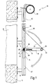
- the retractable awning 10 has two lateral guide rails arranged in mirror image 12 on the brackets 11 on a building 13 are mounted in the area of a window 15 to be shaded.
- a slide 14 is mounted on each rail, which in FIG For the sake of clarity, only indicated by a broken line is.
- a drop arm 16 is mounted, and over the end of its joint 18.
- the connection with the sled 14 takes place via a swivel joint 19, as is shown in more detail in FIG. 8 is shown and will be described later accordingly.
- each drop arm 16 is connected to a down pipe 22 which extends between the two opposite extension arms 16 and how that per se in the construction of such retractable awnings is common.
- the drop arm 16 is at its dropout 20 with a roller 30 (see Fig. 2) connected within the profile the guide rail 12 runs, as the following in more detail is explained, thus the dropout in the guide rail is caught.
- FIG. 2 shows a section of a guide rail 12, that of the guide rail 12 shown in FIG. 1 is a mirror image, that is, in plan view of the Front awning 10, left guide rail.
- the guide rail 12 has an approximately U-shaped profile 32, being inwardly projecting at the outer ends of the U's Crosspieces 34 and 36 are provided, which are approximately parallel to the floor of the U-profile 32. Between the outer opposite The ends of the webs 34 and 36 are not shown here continuous slot opening provided in the profile. Inside the U-profile, the roller 30 is received is connected to the downpipe 32, the connection through the aforementioned long slot opening takes place through.
- the recess 38 is accomplished simply by the U-profile 32 a piece of the web 34 and the side wall of the U-profile 32 is sawn out, so the recess 38 is sufficient is large so that the roller 30 out of the guide rail 12th can leak.
- the position of the recess 38 is such that when a pivot guide 44 at the hinge end of the drop arm 16 with a semicircular Swivel guideway 46 on a pin 48 one Stop 42 in the guide rail 12 hits the roller 30 comes to rest exactly at the level of the recess 38, as in Fig. 3 is shown. Now from the cloth shaft 28 more cloth 24 processed (see Fig. 1), the drop arm 16 can not more vertically downward.
- the drop arm 16 When the cloth is unwound further, the drop arm 16 always becomes pivoted further outward, exceeds that shown in Fig. 1 Swing-out state of 90 ° and for example up to the pivoting angle shown in FIG. 5 up to approx. Swung out 160 °.
- a raising of the arm in the vertical direction i.e. a lifting the drop arm 16 in the guide rail 12 is not possible because this is done by the swivel guide 44 and the pin 48 is blocked. Furthermore, the force of the spring 17 ensures that in the event of gusts of wind the extension arm 16 is not pivoted up. Now becomes even more from the position shown in FIG. 5 Cloth unwound, so the drop arm 16 through an opening 40 re-enter the guide rail 12.
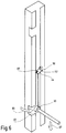
- the opening 40 is recessed like the opening 38 and is located opposite to it in a corresponding one Distance of the length of the drop arm 16 to the pivot pin 48. Is the roller 30 through the opening 40 in again the guide rail 12 entered, as shown in Fig. 6 is, this movement is still by force the spring 17 is supported, the cloth is then 180 ° after pivoted below.
- a corrugated sheet Element 56 is mounted with a shaft contour 58.
- a nipple 16 is mounted in the rail, the head of which in the Shaft contour 38 can retract if the carriage 14 accordingly is lowered.
- an anti-surge device 54 created to lift the slide 11 in gusts of wind locks.
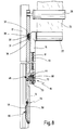
- FIG. 8 corresponds to that in FIG. 3 position shown, i.e. the roller 30 is on Height of recess 38.
- roller 30 has a circumferential groove 31 in which the two Front edges of the opposing webs 34 and 36 be able to walk.
- Fig. 8 it can also be seen that the drop arm 16 over a pivot pin 72 is pivotally mounted on the carriage 14 is.
- the pivot pin 72 carries a washer 68 around which a rope 70 is placed, which is connected to the spring 17.
- the rope 70 at a distance about the pivot axis of the The pivot pin 72 is struck acts on the drop arm 16 permanent torque that is set so that the spring 17 acts on the drop arm 16 in the drop direction, namely with such a strength that it is completely 180 ° is pivoted down, as previously described.
- the nose 50 is on the side, ie off-center on the guide rail 12 mounted.
- Locking or locking the drop arm 16 against leakage from the guide rail 12 and the control of the exit and entry movements of the extension arm 16 are included mechanically simple and robust means in the long run with high Perform operational safety.
Landscapes
- Engineering & Computer Science (AREA)
- Structural Engineering (AREA)
- Architecture (AREA)
- Civil Engineering (AREA)
- Building Awnings And Sunshades (AREA)
Applications Claiming Priority (2)
| Application Number | Priority Date | Filing Date | Title |
|---|---|---|---|
| DE19750985 | 1997-11-18 | ||
| DE1997150985 DE19750985C1 (de) | 1997-11-18 | 1997-11-18 | Ausfallmarkise |
Publications (2)
| Publication Number | Publication Date |
|---|---|
| EP0916780A2 true EP0916780A2 (fr) | 1999-05-19 |
| EP0916780A3 EP0916780A3 (fr) | 2001-07-04 |
Family
ID=7849030
Family Applications (1)
| Application Number | Title | Priority Date | Filing Date |
|---|---|---|---|
| EP98121438A Withdrawn EP0916780A3 (fr) | 1997-11-18 | 1998-11-11 | Store |
Country Status (2)
| Country | Link |
|---|---|
| EP (1) | EP0916780A3 (fr) |
| DE (1) | DE19750985C1 (fr) |
Families Citing this family (1)
| Publication number | Priority date | Publication date | Assignee | Title |
|---|---|---|---|---|
| DE10362024B4 (de) * | 2003-02-17 | 2006-04-27 | Klaus Peter Ranft | Markise, insbesondere zur Verwendung bei einer Pfosten-Riegel-Fassade |
Citations (6)
| Publication number | Priority date | Publication date | Assignee | Title |
|---|---|---|---|---|
| DE1936386A1 (de) | 1969-07-17 | 1971-01-28 | Friedrich Losberger Planen U Z | Markisenbeschlag |
| DE3324170A1 (de) | 1983-07-05 | 1985-01-17 | Merkel GmbH & Co., 8523 Baiersdorf | Markisolette mit ausfallarmen |
| DE3344359A1 (de) | 1983-12-08 | 1985-06-20 | Clauss Markisen, 7311 Bissingen | Fenstermarkise |
| DE9115900U1 (de) | 1991-10-24 | 1992-03-26 | Gallmetzer, Alois, 8523 Baiersdorf | Schwenkhebelgetriebe, insbesondere für Markisen, mit ein- und auskuppelbarem Schwenklager für einen Ausfallarm |
| EP0609175A2 (fr) | 1993-01-19 | 1994-08-03 | Sonne Regen Ag | Store |
| DE19544896C1 (de) | 1995-12-01 | 1997-03-13 | Erwin Frey | Markise mit höhenarretierbarer Markisolettengarnitur und verriegelbarem Markisolettenarm |
Family Cites Families (4)
| Publication number | Priority date | Publication date | Assignee | Title |
|---|---|---|---|---|
| FR788667A (fr) * | 1935-04-12 | 1935-10-14 | Baumann & Fils | Perfectionnements au montage des stores |
| CH193006A (de) * | 1936-11-19 | 1937-09-30 | Schenker Emil | An der äussern Fernsterseite zu befestigende Store. |
| CH192788A (de) * | 1937-02-03 | 1937-09-15 | Rolladenfabrik A Griesser A G | Ausserer Fensterstore. |
| NL1002740C2 (nl) * | 1996-03-29 | 1997-09-30 | Mado Nederland | Zonnescherm. |
-
1997
- 1997-11-18 DE DE1997150985 patent/DE19750985C1/de not_active Expired - Fee Related
-
1998
- 1998-11-11 EP EP98121438A patent/EP0916780A3/fr not_active Withdrawn
Patent Citations (6)
| Publication number | Priority date | Publication date | Assignee | Title |
|---|---|---|---|---|
| DE1936386A1 (de) | 1969-07-17 | 1971-01-28 | Friedrich Losberger Planen U Z | Markisenbeschlag |
| DE3324170A1 (de) | 1983-07-05 | 1985-01-17 | Merkel GmbH & Co., 8523 Baiersdorf | Markisolette mit ausfallarmen |
| DE3344359A1 (de) | 1983-12-08 | 1985-06-20 | Clauss Markisen, 7311 Bissingen | Fenstermarkise |
| DE9115900U1 (de) | 1991-10-24 | 1992-03-26 | Gallmetzer, Alois, 8523 Baiersdorf | Schwenkhebelgetriebe, insbesondere für Markisen, mit ein- und auskuppelbarem Schwenklager für einen Ausfallarm |
| EP0609175A2 (fr) | 1993-01-19 | 1994-08-03 | Sonne Regen Ag | Store |
| DE19544896C1 (de) | 1995-12-01 | 1997-03-13 | Erwin Frey | Markise mit höhenarretierbarer Markisolettengarnitur und verriegelbarem Markisolettenarm |
Also Published As
| Publication number | Publication date |
|---|---|
| EP0916780A3 (fr) | 2001-07-04 |
| DE19750985C1 (de) | 1999-01-28 |
Similar Documents
| Publication | Publication Date | Title |
|---|---|---|
| EP1538271B1 (fr) | Conteneur extensible | |
| EP1772414B1 (fr) | Chasse-pieds pliable auto-bloquant pour cabine d'ascenseur | |
| EP2744962A2 (fr) | Système de porte coulissante et pliante | |
| EP0382172A2 (fr) | Volet à rouleau à persienne | |
| EP2535501B1 (fr) | Dispositif d'ombrage de bâtiments doté de rails de guidage pouvant être sortis | |
| EP0678639B1 (fr) | Dispositif de verrouillage pour volets, portes et éléments similaires mobiles sur un rail fixe | |
| DE19750985C1 (de) | Ausfallmarkise | |
| DE4334519C2 (de) | Senkrechte Markise zur Fensterabdeckung | |
| EP0502352B1 (fr) | Mât télescopique d'une grue mobile ou grue à tour orientable | |
| DE19621956B4 (de) | Markise mit zwangsläufig bewegtem Volant | |
| DE19544896C1 (de) | Markise mit höhenarretierbarer Markisolettengarnitur und verriegelbarem Markisolettenarm | |
| DE19903008C2 (de) | Rolladen | |
| DE3408177C1 (de) | Rolladenjalousie | |
| EP1522650B1 (fr) | Store | |
| DE102020105191B3 (de) | Kranvorrichtung | |
| DE3707521C2 (de) | Teleskopierbarer Kranausleger | |
| EP4065802B1 (fr) | Porte pour un garage, un hall, et analogues, comprenant un système de fermeture pour ouvrir et fermer la baie de porte | |
| CH686794A5 (de) | Store. | |
| DE19601613C2 (de) | Rolladen mit ausschwenkbaren Lamellen | |
| DE8714746U1 (de) | Kombi-Fensterschutz | |
| DE102005015441B4 (de) | Sicht-, Wind- und/oder Sonnenschutzvorrichtung als seitlicher Sicht-, Wind- und/oder Sonnenschutz | |
| WO1998036147A1 (fr) | Store avec garniture a deplacement vertical blocable en hauteur et bras a deplacement vertical verrouillable | |
| DE2225883C3 (de) | Vertikalschiebefenster | |
| DE102014104039B4 (de) | Stehleiter | |
| DE202023103983U1 (de) | Schwimmbecken mit Treppe |
Legal Events
| Date | Code | Title | Description |
|---|---|---|---|
| PUAI | Public reference made under article 153(3) epc to a published international application that has entered the european phase |
Free format text: ORIGINAL CODE: 0009012 |
|
| AK | Designated contracting states |
Kind code of ref document: A2 Designated state(s): AT BE CH CY DE DK ES FI FR GB GR IE IT LI LU MC NL PT SE |
|
| AX | Request for extension of the european patent |
Free format text: AL;LT;LV;MK;RO;SI |
|
| PUAL | Search report despatched |
Free format text: ORIGINAL CODE: 0009013 |
|
| AK | Designated contracting states |
Kind code of ref document: A3 Designated state(s): AT BE CH CY DE DK ES FI FR GB GR IE IT LI LU MC NL PT SE |
|
| AX | Request for extension of the european patent |
Free format text: AL;LT;LV;MK;RO;SI |
|
| RIC1 | Information provided on ipc code assigned before grant |
Free format text: 7E 04F 10/06 A, 7E 06B 9/92 B |
|
| AKX | Designation fees paid | ||
| REG | Reference to a national code |
Ref country code: DE Ref legal event code: 8566 |
|
| STAA | Information on the status of an ep patent application or granted ep patent |
Free format text: STATUS: THE APPLICATION IS DEEMED TO BE WITHDRAWN |
|
| 18D | Application deemed to be withdrawn |
Effective date: 20020103 |