EP0916782A2 - Système de revêtement modulaire - Google Patents
Système de revêtement modulaire Download PDFInfo
- Publication number
- EP0916782A2 EP0916782A2 EP98118568A EP98118568A EP0916782A2 EP 0916782 A2 EP0916782 A2 EP 0916782A2 EP 98118568 A EP98118568 A EP 98118568A EP 98118568 A EP98118568 A EP 98118568A EP 0916782 A2 EP0916782 A2 EP 0916782A2
- Authority
- EP
- European Patent Office
- Prior art keywords
- fastening
- modular system
- elements
- carrier element
- viewing
- Prior art date
- Legal status (The legal status is an assumption and is not a legal conclusion. Google has not performed a legal analysis and makes no representation as to the accuracy of the status listed.)
- Withdrawn
Links
Images

Classifications
-
- A—HUMAN NECESSITIES
- A47—FURNITURE; DOMESTIC ARTICLES OR APPLIANCES; COFFEE MILLS; SPICE MILLS; SUCTION CLEANERS IN GENERAL
- A47K—SANITARY EQUIPMENT; ACCESSORIES THEREFOR, e.g. TOILET ACCESSORIES
- A47K3/00—Baths; Showers; Appurtenances therefor
- A47K3/008—Sealing between wall and bathtub or shower tray
-
- E—FIXED CONSTRUCTIONS
- E04—BUILDING
- E04F—FINISHING WORK ON BUILDINGS, e.g. STAIRS, FLOORS
- E04F13/00—Coverings or linings, e.g. for walls or ceilings
- E04F13/07—Coverings or linings, e.g. for walls or ceilings composed of covering or lining elements; Sub-structures therefor; Fastening means therefor
- E04F13/08—Coverings or linings, e.g. for walls or ceilings composed of covering or lining elements; Sub-structures therefor; Fastening means therefor composed of a plurality of similar covering or lining elements
- E04F13/0801—Separate fastening elements
- E04F13/0803—Separate fastening elements with load-supporting elongated furring elements between wall and covering elements
- E04F13/081—Separate fastening elements with load-supporting elongated furring elements between wall and covering elements with additional fastening elements between furring elements and covering elements
- E04F13/0812—Separate fastening elements with load-supporting elongated furring elements between wall and covering elements with additional fastening elements between furring elements and covering elements fixed by means of spring action
Definitions
- the invention relates to a modular system for covering surfaces and to build functional surfaces and functional walls for wet rooms, the several viewing elements and support elements for fastening the viewing elements on a mounting surface.
- a component is from the German utility model 295 01 954.9 known for covering surfaces with surface elements, in which a plate-like carrier base element is provided which has at least one Has surface element and detachable with both to be clad Surface as well as connected with complementary base elements is.
- the surface elements can either on the carrier base element be fixed or releasably attached, and the basic carrier elements themselves are provided with grooves and tongues, which make a coupling adjacent Allow basic carrier elements.
- the surface elements of which, for example consist of tiles, wood, marble, metal or ceramic elements can, wall coverings, especially in wet rooms, created unlike conventional tiling with less time can be created, are particularly good for renovation purposes suitable and, if necessary, simply removed or modified can be.
- the modular system has several viewing elements has, which are provided on the back with fasteners, that do not protrude beyond the outer contour of the viewing elements.
- the visual elements according to the invention - similar to this conventional tiles is the case - basically from above towards the Place the covering surface without any fastenings protruding from the side.
- the invention for sealing a space between neighboring ones Visible elements or between a visible element and a tub body serves a sealing element, the invention as a separate component is trained.
- the at least one fastening zone for a Fastening means for fastening means, which the carrier element with the fastening surface connects.
- the carrier element can be rail-like be trained. This has the advantage that on a carrier element a variety of viewing elements can be attached, and that the carrier element according to the external circumstances on each desired length can be cut to length. At the same time, the carrier element Manufacture in a material-saving way, since the visible elements do not completely covered.
- the carrier element lies in the fastening zone essentially flat on the fastening surface on, with the attachment zone through a thin-walled Area of the support element can be formed. This results on the one hand stable attachment of the fastener to the mounting surface.
- fasteners for example Attach staples easily in the mounting area as this is thin-walled.
- the carrier element for fastening the visible elements to the fastening surface two differently designed fastenings, preferably a snap fastening and a push-in fixture.
- This embodiment is a very universal modular system created in which the viewing elements First plugged in on one side and then on the other side can be locked. Such attachment allows extremely time-saving installation, since after inserting the viewing element Alignment has already been made in the plug connection, that the locking connection is then made without further alignment can be. Compared to embodiments where only Plug connections are available, this will save a considerable amount of time achieved during assembly because the assembly process starts of the viewing element on the plug connection thus comprises the viewing element is fully aligned and only needs to be locked.
- the plug-in fastening can advantageously comprise a projection, that engages behind the visual element or a part of the visual element can be, the projection is preferably an oblique Has rest area.
- the latching attachment can, for example, by an arrowhead profile can be formed, on which a corresponding complementary trained area of the viewing element is snapped on.
- the carrier element When viewed in cross section, the carrier element preferably has one End the mounting receptacle, which makes the sealing element easy can be attached in the edge area of a viewing element.
- the carrier element has two fastening receptacles for sealing elements, which are preferably perpendicular to each other are oriented and which preferably have a snap fastening.
- the cladding system on the one hand provided with a sealing element at its lower edge for example to seal against a shower tray.
- a sealing profile can be inserted into the second fastening receptacle that seals against the visible element installed above, so that no moisture behind the visual elements and thus can get into the masonry.
- a corner element can be provided for the corner area of the modular system be that between two right-angled viewing elements is plugged in, so that a good finish in the area of the corner is created between the visual elements.
- a sealing element may also be provided between two Carrier elements mounted at right angles to one another is inserted. Especially can this sealing element in parallel to the mounting surface oriented mounting brackets. This is also A seal is created in the corner area so that no moisture can penetrate into the masonry through the corner area.
- the carrier element of the modular system a molded stop for the viewing element on. This makes it easy to achieve an accurate position of the visible elements after assembly.
- the latching opening of the carrier element can preferably be a run-up slope have, which protrudes over a locking hook of the locking opening.
- the sealing element can be particularly easily inserted into the latching opening insert it, this after exceeding the locking hook in the Locking opening are fixed.
- the fasteners can, for example, on the viewing elements be fixed by gluing. However, it is also a one-piece training the view elements and the fastening elements possible.
- the fastening means a snap fastening and has a plug-in fastening, since in this case the viewing element for Assembly does not have to be rotated, but on both sides with both the corresponding latching or plug-in fastening of the carrier element can engage.
- the fastener rail-like and preferably extruded since this is an inexpensive Manufacturing and cutting to any desired length enables.
- the fastener fastened to the viewing elements preferably has a snap fastener and a push-fit
- the push-fit can be formed by a projection which has a locking hook owns. This allows another element behind the projection insert, which is locked by the locking hook.
- the modular system can have a corner element attached to its Back two shots for an edge area of a viewing element has and which is preferably curved in cross section.
- a corner element can be easily rectangular at two Attach the visible elements to each other and form one visually appealing and easy to clean finish.
- a sealing element for the modular system according to the invention is preferred a trapezoidal in cross section and preferably rail-like trained element provided. This can be done very easily in the Fastening receptacles can be inserted from two support elements are mounted at right angles to each other, so that a Moisture barrier is given.
- Another sealing element can have a lambda-shaped cross section be and have a molded arrow projection at its end.
- Such a sealing element can be on the underside of the clad Insert the surface into the mounting receptacle of the carrier element, whereby a moisture seal to a shower tray or the like is formed. It is particularly advantageous here if the fastening receptacle is dimensioned so that an additional hollow profile seal can be used. This can improve the sealing effect and is a height compensation for shower trays of different heights ensured.
- Fig. 1 shows a first embodiment of a modular system for Creation or covering of wall, ceiling and / or floor surfaces as well as for the construction of functional surfaces and functional walls in one Damp room.
- the system consists of several visual elements 10, 12, the one on the back, i.e. on their opposite side Side, are provided with fasteners 18, 20. These fasteners do not protrude beyond the outer contour of the viewing elements 10, 12, but are arranged on the back.
- FIG. 1 there is a fastening means on the underside of the viewing element 10 18 glued, which is rail-like and one Cross section forms, which has a latching opening 22 with a conical inlet 23 and forms a projection 24 that leads to the rear of the viewing element 10 creates a free space 26. There is a locking hook at the end of the projection 25 molded.
- the viewing elements 10, 12 are plate-shaped and have in Area of their edges a chamfer 28.
- the attachment of the viewing elements 10, 12 on the fastening surface 30 is carried out with the aid of a carrier element 32, which is formed like a rail as an extrusion.
- the support element 32 seen in cross-section, has a snap fastening on one side 34 in the form of an arrowhead profile that is rectangular extends to the mounting surface 32, and on the opposite Side a mounting receptacle 36 in the form of a U-shaped profile section, locking projections are formed on the leg ends.
- the carrier element has a fastening zone 58 for a mounting means 40.
- the mounting receptacle 36 of the support member 32 is parallel to that Mounting surface oriented, i.e. a sealing element can be parallel to the Mounting surface 30 are inserted into the mounting receptacle 36.
- the system shown in FIG. 1 also has a sealing element 41 which consists of a profile rail trapezoidal in cross section, the Leg ends have a molded-on widening projection.
- the sealing element 41 is in the fastening receptacles oriented at right angles to one another 36 of the carrier elements 32 inserted and in this locked.
- the mounting receptacles have an easier insertion 36 each have a run-up slope 37, which is extended by a Leg of the support member 32 is formed and the associated one Locking hook 38 protrudes.
- corner element in the corner area of the modular system of FIG. 1 46 is provided, which is curved in cross section and on a molded receptacle 48 for each of the two inner outer ends having.
- the two receptacles 48 are oriented at right angles to one another and open away from each other so that the corner element 46 on the Outer edges of the two viewing elements 10 and 12 are attached can.
- the carrier element is first 32 cut to the desired length and then by means of a stapling device on the fastening surface 30, for example a plasterboard wall, fastened by staples 40 through the support member 32 are driven into the mounting surface 30.
- a stapling device on the fastening surface 30, for example a plasterboard wall, fastened by staples 40 through the support member 32 are driven into the mounting surface 30.
- the stapler can be advantageous in the area of the strip Fastening zone 58 are set and operated.
- the sealing element 41 is in the Fastening receptacles 36 of the support elements mounted at right angles to one another 32 used, which creates a moisture barrier in the corner area given is.
- the viewing element 12 with the diffraction means 20 plugged onto the snap fastening 34 of the carrier element 32 become.
- the viewing element 10 is with the locking opening 22 of the Fastening means 18 on the arrowhead profile 34 of the carrier element 32 inserted.
- the carrier element 32 is in the fastening zone 58 substantially flat on the fastening surface 30 formed overlying, the fastening zone 58 by a thin-walled region of the support element 32 is formed, the opposite the locking fastener 34 is formed deeper.
- corner element 46 After assembly of the viewing elements 10 and 12, the corner element 46 attached to the edge areas of the viewing elements 10 and 12, what by a certain flexible design of the corner element 46 is possible.
- Fig. 2 shows a further embodiment of a carrier element 32 ', the at its one end (in Fig. 2 upper end) a snap fastener 34 'in shape of an arrowhead profile that is perpendicular to the carrier element 32 ' is oriented.
- a plug-in fastening 39 ' is provided in the form of an elevated projection, which is at its front end in the direction of that formed by the projection Tapered interior.
- two attachment receptacles 42', 44 ' are provided between the plug attachment 'and the latching attachment 34 '.
- a fastening zone 58' Between the mounting receptacle 44 'and the snap fastening 34 'there is a fastening zone 58' which has a projection 31 ' having.
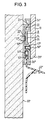
- Fig. 3 shows the cross-sectional view of the lower edge area of the modular Systems, wherein here a support element 32 '' is provided, which one end (in FIG. 3) of a snap fastening 34 ′′ in the form of a Arrow projection and at its other (lower in Fig. 3) end one Fastening receptacle 36 '', which is formed by a U-profile section is, the inner leg ends each have a locking hook.
- Immediately following the mounting receptacle 36 '' is one further mounting receptacle 42 '' is provided, into which a sealing profile 50 '' is inserted.
- a fastening zone 58 '' Between the mounting receptacle 42 '' and the snap fastening 34 '' there is a fastening zone 58 '' in which a mounting means 40 '' in the form of a staple in the mounting surface 30 '' is.
- a another sealing profile 52 '' used seen in cross section about is lambda-shaped and made of soft elastic material is.
- Leg is the sealing profile 52 '' with a molded-on arrow projection 53 '' provided, which in the mounting receptacle 36 '' of the support member 32 '' is inserted.
- the sealing profile 52 '' is used to seal against a shower tray, a vertical one due to the design of the mounting receptacle 36 ′′ Height adjustment is possible.
- Another seal is inside the fastening receptacle 36 '' is provided with a further sealing profile 54 '', that (like the sealing profile 50 ′′) a closed cross-sectional shape having.
- the sealing profile 54 ′′ exerts a certain pressure on the one hand the sealing profile 52 '', so that it seals well. On the other hand, it is Moisture penetration inside the modular cladding system prevented.
- support elements or visual elements can be used that are similar trained fastening means, for example arrowhead profiles, to form edge seals, edge seals or the like.
Landscapes
- Engineering & Computer Science (AREA)
- Architecture (AREA)
- Health & Medical Sciences (AREA)
- Public Health (AREA)
- Civil Engineering (AREA)
- Structural Engineering (AREA)
- Epidemiology (AREA)
- General Health & Medical Sciences (AREA)
- Finishing Walls (AREA)
- Casings For Electric Apparatus (AREA)
Applications Claiming Priority (2)
| Application Number | Priority Date | Filing Date | Title |
|---|---|---|---|
| DE1997150565 DE19750565A1 (de) | 1997-11-14 | 1997-11-14 | Modulares Verkleidungssystem |
| DE19750565 | 1997-11-14 |
Publications (2)
| Publication Number | Publication Date |
|---|---|
| EP0916782A2 true EP0916782A2 (fr) | 1999-05-19 |
| EP0916782A3 EP0916782A3 (fr) | 1999-08-04 |
Family
ID=7848795
Family Applications (1)
| Application Number | Title | Priority Date | Filing Date |
|---|---|---|---|
| EP98118568A Withdrawn EP0916782A3 (fr) | 1997-11-14 | 1998-10-01 | Système de revêtement modulaire |
Country Status (2)
| Country | Link |
|---|---|
| EP (1) | EP0916782A3 (fr) |
| DE (1) | DE19750565A1 (fr) |
Cited By (1)
| Publication number | Priority date | Publication date | Assignee | Title |
|---|---|---|---|---|
| GB2468116A (en) * | 2009-01-26 | 2010-09-01 | Michael Herbert Charles Smith | Sanitary-ware sealing system |
Citations (1)
| Publication number | Priority date | Publication date | Assignee | Title |
|---|---|---|---|---|
| DE29501954U1 (de) | 1995-02-07 | 1995-06-14 | Bub, Frank-Martin, Dipl.-Kaufm., 57072 Siegen | Bauelement zur Verkleidung von Flächen mit Oberflächenelementen |
Family Cites Families (5)
| Publication number | Priority date | Publication date | Assignee | Title |
|---|---|---|---|---|
| US4829740A (en) * | 1987-10-19 | 1989-05-16 | Dunmon Corporation | Apparatus for joining wall panels |
| GB2230029A (en) * | 1989-04-07 | 1990-10-10 | Arne Norderhaug | Push-fit cladding system |
| US5263292A (en) * | 1991-01-07 | 1993-11-23 | American Wall Products | Building panel system |
| GB9411173D0 (en) * | 1994-06-03 | 1994-07-27 | Mccomb Barry H | Sanitary ware seal |
| NL9500419A (nl) * | 1995-03-03 | 1996-10-01 | Anton Tapper | Samenstel omvattende een paneel en een profiel, alsmede veerelement, paneel, profiel en vormstrip geschikt voor toepassing in een dergelijk samenstel. |
-
1997
- 1997-11-14 DE DE1997150565 patent/DE19750565A1/de not_active Withdrawn
-
1998
- 1998-10-01 EP EP98118568A patent/EP0916782A3/fr not_active Withdrawn
Patent Citations (1)
| Publication number | Priority date | Publication date | Assignee | Title |
|---|---|---|---|---|
| DE29501954U1 (de) | 1995-02-07 | 1995-06-14 | Bub, Frank-Martin, Dipl.-Kaufm., 57072 Siegen | Bauelement zur Verkleidung von Flächen mit Oberflächenelementen |
Cited By (1)
| Publication number | Priority date | Publication date | Assignee | Title |
|---|---|---|---|---|
| GB2468116A (en) * | 2009-01-26 | 2010-09-01 | Michael Herbert Charles Smith | Sanitary-ware sealing system |
Also Published As
| Publication number | Publication date |
|---|---|
| EP0916782A3 (fr) | 1999-08-04 |
| DE19750565A1 (de) | 1999-05-20 |
Similar Documents
| Publication | Publication Date | Title |
|---|---|---|
| DE4215273C2 (de) | Belag zur Verkleidung von Boden-, Wand- und/oder Deckenflächen, insbesondere in der Art eines Riemenfußbodens | |
| EP1319773B1 (fr) | Eléments de construction en forme de panneaux ou bandes | |
| DE4030117C2 (de) | Abgehängte Kassettendecke | |
| EP1527241B1 (fr) | Dispositif d'assemblage de deux panneaux en forme de dalles | |
| DE10107864C2 (de) | Halteelement für Abdeckleisten | |
| DE29716146U1 (de) | Vorrichtung zum Befestigen von Abschlußleisten | |
| DE19800517C1 (de) | Mehrzweckleiste | |
| AT500181B1 (de) | Tür- oder fensterbeschlag | |
| DE20002298U1 (de) | Bausatz für die Befestigung von Flächenbelägen auf Flächen | |
| EP0916782A2 (fr) | Système de revêtement modulaire | |
| EP0908577A2 (fr) | Système de revêtement modulaire | |
| DE19903133C2 (de) | System zur Befestigung von Täfelungsplatten, wie Paneelen, Profilbrettern, und Nut- und Federbrettern vor Wänden, Decken oder Böden | |
| EP1001103A2 (fr) | Profilé de bordure pour revêtement de mur | |
| EP1646756B1 (fr) | Systeme d'assemblage pour rails profiles | |
| EP1709887A2 (fr) | Garniture d'angle avec plinthes | |
| DE4013459A1 (de) | Befestigungsvorrichtung fuer eine abschlussleiste | |
| EP0027196B1 (fr) | Structure de recouvrement avec dispositif de pinçage et élément de recouvrement | |
| DE19741526A1 (de) | Türzarge | |
| DE2825705A1 (de) | Aus haltelatten und paneelen bestehende decken- oder wandverkleidung | |
| DE19514149A1 (de) | Anschlußfutter für einen Fensterrahmen | |
| WO2008049540A1 (fr) | Système de fixation et procédé pour la fixation d'au moins un panneau par un bord et/ou par un coin | |
| DE19835204B4 (de) | Befestigungsband und Holzbalkenkonstruktion mit Befestigungsband | |
| DE8516815U1 (de) | Befestigungselement | |
| EP0947644A2 (fr) | Elément de fixation | |
| DE202019105093U1 (de) | Befestigungsklammer zur unsichtbaren Verbindung von Holzbauteilen |
Legal Events
| Date | Code | Title | Description |
|---|---|---|---|
| PUAI | Public reference made under article 153(3) epc to a published international application that has entered the european phase |
Free format text: ORIGINAL CODE: 0009012 |
|
| AK | Designated contracting states |
Kind code of ref document: A2 Designated state(s): AT BE CH CY DE DK ES FI FR GB GR IE IT LI LU MC NL PT SE |
|
| AX | Request for extension of the european patent |
Free format text: AL;LT;LV;MK;RO;SI |
|
| PUAL | Search report despatched |
Free format text: ORIGINAL CODE: 0009013 |
|
| AK | Designated contracting states |
Kind code of ref document: A3 Designated state(s): AT BE CH CY DE DK ES FI FR GB GR IE IT LI LU MC NL PT SE |
|
| AX | Request for extension of the european patent |
Free format text: AL;LT;LV;MK;RO;SI |
|
| RAP1 | Party data changed (applicant data changed or rights of an application transferred) |
Owner name: GE PLASTICS & LOGYDESIGN GESELLSCHAFT ZUR VERWERTU |
|
| AKX | Designation fees paid | ||
| REG | Reference to a national code |
Ref country code: DE Ref legal event code: 8566 |
|
| STAA | Information on the status of an ep patent application or granted ep patent |
Free format text: STATUS: THE APPLICATION IS DEEMED TO BE WITHDRAWN |
|
| 18D | Application deemed to be withdrawn |
Effective date: 20000205 |