EP0916880A2 - Be- und Entlüftungsventil - Google Patents
Be- und Entlüftungsventil Download PDFInfo
- Publication number
- EP0916880A2 EP0916880A2 EP98118242A EP98118242A EP0916880A2 EP 0916880 A2 EP0916880 A2 EP 0916880A2 EP 98118242 A EP98118242 A EP 98118242A EP 98118242 A EP98118242 A EP 98118242A EP 0916880 A2 EP0916880 A2 EP 0916880A2
- Authority
- EP
- European Patent Office
- Prior art keywords
- valve
- passage
- valve body
- valve according
- housing
- Prior art date
- Legal status (The legal status is an assumption and is not a legal conclusion. Google has not performed a legal analysis and makes no representation as to the accuracy of the status listed.)
- Withdrawn
Links
Images



Classifications
-
- F—MECHANICAL ENGINEERING; LIGHTING; HEATING; WEAPONS; BLASTING
- F16—ENGINEERING ELEMENTS AND UNITS; GENERAL MEASURES FOR PRODUCING AND MAINTAINING EFFECTIVE FUNCTIONING OF MACHINES OR INSTALLATIONS; THERMAL INSULATION IN GENERAL
- F16K—VALVES; TAPS; COCKS; ACTUATING-FLOATS; DEVICES FOR VENTING OR AERATING
- F16K17/00—Safety valves; Equalising valves, e.g. pressure relief valves
- F16K17/18—Safety valves; Equalising valves, e.g. pressure relief valves opening on surplus pressure on either side
-
- F—MECHANICAL ENGINEERING; LIGHTING; HEATING; WEAPONS; BLASTING
- F16—ENGINEERING ELEMENTS AND UNITS; GENERAL MEASURES FOR PRODUCING AND MAINTAINING EFFECTIVE FUNCTIONING OF MACHINES OR INSTALLATIONS; THERMAL INSULATION IN GENERAL
- F16K—VALVES; TAPS; COCKS; ACTUATING-FLOATS; DEVICES FOR VENTING OR AERATING
- F16K24/00—Devices, e.g. valves, for venting or aerating enclosures
Definitions
- the invention relates to a valve, in particular for ventilation.
- the valve solving this problem according to the invention is characterized by a sealingly against a first and second passage restriction, depending on the direction of a pressure drop across the valve to form a Opening passage at the first or second passage limitation through the pressure drop is elastically deformable.
- an elastically deformable valve body ensures that Valve opening for opposite flow directions, i.e. e.g. the valve opening both for ventilation as well as ventilation.
- the valve body is for the sealing system elastically deformable against the passage limits so that the pressure drop depending on its direction the sealing pressure of the valve body for the first or second passage restriction reinforced.
- the sealing pressure at the passage limit increases, at which the opening passage for ventilation is formed, thereby securing is that a vent or a gas outlet only through the other passage restriction formed opening passage at a defined pressure difference between Inside and outside pressure takes place.
- the opening passage pressure difference required at the first or second passage restriction can be different.
- vessel ventilation via the valve can already be used very low negative pressure in the vessel, while gas is only released via the valve starts at a much higher pressure in the vessel.
- the valve body lies against the respective one Flow restrictions in the manner of a depending on the direction of the pressure drop from the Passage limit swiveling away or swiveling towards the passage limit Lip on.
- the valve body is preferably located with a peripheral edge against the first passage limit and with the peripheral edge a particularly central recess against the second passage limit, where the valve body is essentially rotationally symmetrical in the manner of a membrane-like one in particular Shell with a reverse of the shell curvature from the shell bottom extending bulge having the recess is formed.
- valve body in a valve housing having inlet or outlet openings in a recess in particular coaxially surrounding ring area.
- Bracket is for the parts of the rotationally symmetrical against the passage limits Valve body an unhindered freedom of movement to form the respective Opening passage or to reinforce the sealing system.
- the annular holding region is preferably in a transition section between the opposite curved parts of the valve body are provided so that the bracket the mobility of the valve body parts facing the passage limits not affected.
- valve body is, in particular, form-fitting, arranged between bracket parts, which into the valve housing protrude from opposite sides.
- the valve body preferably has at least on one side an annular groove for receiving such bracket parts.
- mounting parts stand up a valve housing side from one with the valve housing in particular via a plug / snap connection connectable housing cover, the housing cover preferably one, in particular formed by an indentation, under Forming the second passage limit to the recess extending projection.
- Such a protrusion can be used, particularly for engaging in the above provided mentioned, groove parts extend.
- these mounting parts extend from an annular shoulder of the protrusion, and the protrusion faces to form the second passage restriction an end portion with a reduced diameter.
- the valve body, the mounting parts and the projection are substantially coaxial with one another and in particular coaxial with a preferably cylindrical valve housing, the first passage restriction through the cylinder wall of the valve housing against which the valve body rests with its peripheral edge is formed.
- the valve housing can be part of a container closure or even in a container closure be screwable.
- valve housing has a shielding the housing inputs and outputs from the ingress of liquids on.
- a thread 2 of the Screw cap is for engagement in a corresponding external thread, on an extension piece of the container provided.
- the screw cap 1 has a central internal thread 4, into which a corresponding one External thread provided valve 3 is screwed.
- a ring seal 5 ensures a closure of the formed between the screw closure 1 and the valve 3 Thread gap.
- the valve 3 comprises a cylindrical housing wall bearing said external thread 6 and an end wall 7. Of the end wall 7 are each in an annular arrangement in each case four mounting parts 8 and 9, respectively, between the mounting parts 8 and 9 in Ring circumferential direction distributed through openings 10 are provided.
- a housing cover 11 On the housing side opposite the end wall 7 there is a housing cover 11 arranged, which can be inserted at the end into the hollow cylinder formed by the cylinder wall 6 is, for fastening the housing cover 11 to the rest of the housing from the housing cover 11 to the housing interior four locking lugs 12 protrude engage in corresponding recesses 13 in the cylinder wall 6.
- the housing cover 11 has an indentation through which a projection 14 with a reduced diameter end portion 15 and Ring shoulder 16 is formed. Extend from the annular shoulder 16 along an annular region four mounting parts 17. Around the ring circumference are distributed between the four mounting parts 17 passage openings 18 are provided.
- the reference numeral 22 denotes a rotationally symmetrical valve body, which in the The embodiment shown is designed as a bowl-shaped membrane, which on has an annular groove 23 on its side facing the housing cover 11.
- the membrane material based on the shell edge plane, curved opposite to the rest of the bowl-shaped membrane.
- the valve On the side opposite the housing cover 11, the valve has one Lid extension 50 on which an annular shoulder 51 for the system against the sealing ring 5 and a cross-shaped recess 26 is formed.
- the lid extension 50 also has an annular protruding edge part 27 which extends approximately to parts 28 which protrude from the screw cap 1, being distributed in the embodiment shown around the valve 3 four such protruding parts 28 are provided.
- valve 30 designates a bulge provided in the bottom of the recess 26 through which a corresponding part of the end wall 7 of the valve housing projects into the valve housing.
- Reference number 31 denotes a gas-permeable wall held on webs 32 designated, which the indentation and the openings 19 to the container interior covers.
- This wall can e.g. be lattice-like or consist of a textile material (e.g. Goretex).
- valve 3 To assemble the valve 3 described in FIGS. 1 to 8, it is used as a shell-like membrane trained valve body 22 attached to the housing cover 11, the Bracket parts 17 in engagement with the annular groove 23 and the recess 25 over its circumference in Sealing system against the rounded end portion 15 of the projection 14.
- the Housing cover 11 with the valve body 22 can now on the open end of the the cylinder wall 6 formed hollow cylinder are plugged, the locking lugs 12th the housing cover 11 get into the recesses 13 of the cylinder wall 6.
- Through the protruding nose 20 and the corresponding recess 21 on the cylinder wall 6 ensures that the attachment of the housing cover 11 only in one certain position can take place by the latching of the lugs 12 in the locking recesses 13 is guaranteed.
- valve body 22 lies in an annular area against the mounting parts 17 and the bracket parts 17 opposite bracket parts 7 and 8 on.
- the peripheral edge of the valve body 22 is in sealing system against the Inside of the cylinder wall 6.
- the housing cover 11 lies with an edge projecting beyond the locking lugs 12 against the front edge of the cylinder wall 6.
- the screw cap shown in FIGS. 1 and 2 can be assembled 1 the valve is screwed into the thread 4 of the screw cap 1 and over the ring seal 5 be sealed around the circumference.
- a screw could be screwed into the recess 26 or the openings 28 engaging tool can be used.
- valve body 22 is shaped and annular supported that the pressure difference required for ventilation is much less than that Pressure difference, which is necessary so that in the event of overpressure in the interior of the gas through the Valve can flow outwards. That means it's a much larger pressure differential required an opening passage between the end portion 15 and the edge of the recess 25 than between the peripheral edge of the valve body 22 and the cylinder wall 6 of the To form the valve housing.
- the gases entering and exiting the vessel each pass through the passage openings 18 between the mounting parts 17 and through the openings 10 between the mounting parts 8 and 9 through.
- the permeable wall 31 which the indentation forming the projection 14 and the Breakthroughs 19 covers, ensures that no fluid in the valve during movements can penetrate, for example, as a result of movements of one through the screw cap sealed vessel gush occurring in the vessel.
- the edge part 27 on the cover extension 50 of the valve covers the passage channels 52 so that Do not immediately drop drops of liquid, especially as a result of rain falling diagonally into the Passage channels can enter.
- the parts 28 protruding from the screw closure 1 prevent screwing in and unscrewing of the closure a turning of the valve 3 and also form beads, the closure, particularly in the area of the internal thread 4, has a high dimensional stability to lend.
- valve body 22 is between one another Bracket parts 9 and 17 held while the bracket parts 8 of this annular Bracket are offset and thus the mobility of the valve body 22 in Affect area of their peripheral edge.
- bracket parts 8 decisive for the pressure difference required for ventilation.
Landscapes
- Engineering & Computer Science (AREA)
- General Engineering & Computer Science (AREA)
- Mechanical Engineering (AREA)
- Self-Closing Valves And Venting Or Aerating Valves (AREA)
- Filling Or Discharging Of Gas Storage Vessels (AREA)
- Closures For Containers (AREA)
Abstract
Description
- Fig. 1
- ein Ausführungsbeispiel für ein erfindungsgemäßes Ventil, daß in einen Behälterschraubverschluß eingeschraubt ist, in einer geschnittenen Seitenansicht,
- Fig. 2
- das Ventil von Fig. 1 in einer einen Ausschnitt aufweisenden perspektivischen Ansicht,
- Fig. 3
- ein Ventilgehäuseteil des Ventils von Fig. 1 und 2 in einer perspektivischen Ansicht,
- Fig. 4
- das Ventilgehäuseteil von Fig. 3 in einer weiteren perspektivischen Ansicht,
- Fig. 5
- einen in dem Ventil gemäß den Fig. 1 und 2 verwendeten Ventilkörper,
- Fig. 6
- ein weiteres Gehäuseteil des Ventils von Fig. 1 und 2 in einer geschnittenen Seitenansicht,
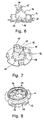
- Fig. 7
- das Gehäuseteil von Fig. 6 in einer perspektivischen Ansicht,
- Fig. 8
- das Gehäuseteil von Fig. 6 und 7 in einer weiteren perspektivischen Ansicht, und
- Fig. 9
- geschnittene Teilansichten des Ventils von Fig. 1 und 2 zur Erläuterung der Arbeitsweise des Ventils.
Claims (18)
- Ventil, insbesondere für die Be- und Entlüftung,
gekennzeichnet durch einen abdichtend gegen eine erste (6) und zweite (15) Durchlaßbegrenzung anliegenden Ventilkörper (22), der je nach Richtung eines über dem Ventil (3) anliegenden Druckgefälles zur Bildung eines Öffnungsdurchlasses (40,54) an der ersten oder zweiten Durchlaßbegrenzung (6,15) durch das Druckgefälle elastisch verformbar ist. - Ventil nach Anspruch 1,
dadurch gekennzeichnet,
daß der Ventilkörper (22) zur Abdichtungsanlage gegen die Durchlaßbegrenzungen (6,15) elastisch derart verformbar ist, daß das Druckgefälle je nach seiner Richtung den Dichtungsandruck des Ventilkörpers (22) gegen die erste (6) oder zweite (15) Durchlaßbegrenzung verstärkt. - Ventil nach Anspruch 1 oder 2,
dadurch gekennzeichnet,
daß der Ventilkörper (22) gegen die jeweiligen Durchlaßbegrenzungen (6,15) in der Art einer je nach Richtung des Druckgefälles von der Durchlaßbegrenzung abschwenkbaren oder auf die Durchlaßbegrenzung zuschwenkbaren Lippe anliegt. - Ventil nach einem der Ansprüche 1 bis 3,
dadurch gekennzeichnet,
daß der Ventilkörper (22) mit einem Umfangsrand gegen die erste Durchlaßbegrenzung (6) und mit dem Umfangsrand einer insbesondere zentralen Ausnehmung (25) gegen die zweite Durchlaßbegrenzung (15) anliegt. - Ventil nach Anspruch 4,
dadurch gekennzeichnet,
daß der Ventilkörper (22) im wesentlichen rotationssymmetrisch in der Art einer insbesondere membranartigen Schale (22) vorzugsweise mit einer sich unter Umkehrung der Schalenkrümmung vom Schalenboden erstreckenden, die Ausnehmung (25) aufweisenden Ausbuchtung (24) ausgebildet ist. - Ventil nach Anspruch 4 oder 5,
dadurch gekennzeichnet,
daß der Ventilkörper (22) in einem Ein- bzw. Auslaßöffnungen (19,52) aufweisenden Ventilgehäuse in einem die Ausnehmung (25) insbesondere koaxial umgebenden Ringbereich gehaltert ist. - Ventil nach Anspruch 5 oder 6,
dadurch gekennzeichnet,
daß der Ventilkörper (22) in einem Übergangsbereich zwischen entgegengesetzt gekrümmten Abschnitten des Ventilkörpers gehaltert ist. - Ventil nach einem der Ansprüche 1 bis 7,
dadurch gekennzeichnet,
daß der Ventilkörper, insbesondere formschlüssig zwischen Halterungsteilen (8,9;17), die von gegenüberliegenden Seiten in ein Ventilgehäuse hinein vorstehen, angeordnet ist. - Ventil nach einem der Ansprüche 1 bis 8,
dadurch gekennzeichnet,
daß der Ventilkörper (22) eine Ringnut (23) für die Aufnahme von Halterungsteilen (17) aufweist. - Ventil nach einem der Ansprüche 1 bis 9,
dadurch gekennzeichnet,
daß Halterungsteile (17) auf einer Ventilgehäuseseite von einer mit dem Ventilgehäuse, insbesondere über eine Steck-/Schnappverbindung, verbindbaren Gehäuseabdeckung (11) vorstehen. - Ventil nach Anspruch 10,
dadurch gekennzeichnet,
daß die Gehäuseabdeckung (11) einen, insbesondere durch eine Einbuchtung gebildeten, sich unter Bildung der zweiten Durchlaßbegrenzung zu der Ausnehmung (25) erstreckenden Vorsprung (14) aufweist. - Ventil nach Anspruch 11.
dadurch gekennzeichnet,
daß sich von dem Vorsprung Halterungsteile (17), insbesondere für den Eingriff in die Ringnut (23), erstrecken. - Ventil nach Anspruch 12,
dadurch gekennzeichnet,
daß sich die Halterungsteile (17) von einer Ringschulter (16) des Vorsprungs (14) erstrecken und die Durchlaßbegrenzung durch einen verjüngten Endteil (15) des Vorsprungs (14) gebildet ist. - Ventil nach Anspruch 12 oder 13,
dadurch gekennzeichnet,
daß der Ventilkörper (22), die Halterungsteile (8,9;17) und der Vorsprung (14) im wesentlichen koaxial zueinander und insbesondere koaxial einem vorzugsweise zylindrischen Ventilgehäuse ausgebildet sind. - Ventil nach Anspruch 14,
dadurch gekennzeichnet,
daß die erste Durchlaßbegrenzung durch die Zylinderwand (6) des Ventilgehäuses, gegen die der Ventilkörper (22) mit seinem Umfangsrand anliegt, gebildet ist. - Ventil nach einem der Ansprüche 1 bis 15,
dadurch gekennzeichnet,
daß zur Bildung des Öffnungsdurchlasses (40,54) an der ersten oder zweiten Durchlaßbegrenzung (6,15) erforderliche Druckdifferenzen unterschiedlich sind. - Ventil nach einem der Ansprüche 1 bis 16,
dadurch gekennzeichnet,
daß das Ventil (3) Bestandteil eines insbesondere schraubbaren Behälterverschlusses oder mit einem Behälterverschluß (1) insbesondere über eine Schraubverbindung (4) verbindbar ist. - Ventil nach einem der Ansprüche 1 bis 17,
dadurch gekennzeichnet,
daß das Ventilgehäuse eine Ein- bzw. Ausgänge des Ventilgehäuses vor dem Eindringen von Flüssigkeit schützende Abschirmung (27;30) aufweist.
Applications Claiming Priority (2)
| Application Number | Priority Date | Filing Date | Title |
|---|---|---|---|
| DE19746106 | 1997-10-17 | ||
| DE1997146106 DE19746106A1 (de) | 1997-10-17 | 1997-10-17 | Ventil |
Publications (2)
| Publication Number | Publication Date |
|---|---|
| EP0916880A2 true EP0916880A2 (de) | 1999-05-19 |
| EP0916880A3 EP0916880A3 (de) | 2000-10-04 |
Family
ID=7845948
Family Applications (1)
| Application Number | Title | Priority Date | Filing Date |
|---|---|---|---|
| EP98118242A Withdrawn EP0916880A3 (de) | 1997-10-17 | 1998-09-25 | Be- und Entlüftungsventil |
Country Status (2)
| Country | Link |
|---|---|
| EP (1) | EP0916880A3 (de) |
| DE (1) | DE19746106A1 (de) |
Families Citing this family (2)
| Publication number | Priority date | Publication date | Assignee | Title |
|---|---|---|---|---|
| DE10103275B4 (de) * | 2001-01-25 | 2006-06-22 | Busak + Shamban Deutschland Gmbh | Dichtungsventilanordnung |
| DE102011052525B3 (de) * | 2011-08-09 | 2012-05-10 | Argo-Hytos Gmbh | Vorrichtung zum Be- und Entlüften eines Öltanks |
Family Cites Families (6)
| Publication number | Priority date | Publication date | Assignee | Title |
|---|---|---|---|---|
| FR1141660A (fr) * | 1956-11-14 | 1957-09-05 | Renault | Soupape de décharge |
| FR2503892A1 (fr) * | 1981-04-10 | 1982-10-15 | Mecanismes Comp Ind De | Clapet de regulation de pression |
| JPS57191131A (en) * | 1981-05-21 | 1982-11-24 | Yamaha Motor Co Ltd | Cap for fuel tank |
| US4726390A (en) * | 1986-03-26 | 1988-02-23 | Waltec, Inc. | Hose bibb vacuum breaker |
| US4922954A (en) * | 1988-03-04 | 1990-05-08 | Kelch Corp. | Bi-directional pressure relief vent for a fuel tank |
| JP2559176Y2 (ja) * | 1992-07-13 | 1998-01-14 | 自動車機器株式会社 | マスタシリンダ用リザーバのキャップ |
-
1997
- 1997-10-17 DE DE1997146106 patent/DE19746106A1/de not_active Withdrawn
-
1998
- 1998-09-25 EP EP98118242A patent/EP0916880A3/de not_active Withdrawn
Also Published As
| Publication number | Publication date |
|---|---|
| DE19746106A1 (de) | 1999-04-22 |
| EP0916880A3 (de) | 2000-10-04 |
Similar Documents
| Publication | Publication Date | Title |
|---|---|---|
| DE69601132T2 (de) | Gasventil zur bereitstellung eines gasimpulses | |
| DE3751225T2 (de) | Zylinderförmiger luftfilter mit leichtem gehäuse und radialabdichtung. | |
| DE2820258C2 (de) | Füllstutzenkappe | |
| EP0377067A1 (de) | Sperrvorrichtung für abgedichtete Gehäuse | |
| EP2361599A1 (de) | Vorrichtung zum Zuführen oder Entnehmen einer Flüssigkeit in ein oder aus einem Behältnis | |
| DE10108248A1 (de) | Brausekopf | |
| DE8900483U1 (de) | Druckbehälter, insbesondere Druckspeicher | |
| WO2010040368A1 (de) | Atemschutzmaske | |
| WO2020164902A1 (de) | Druckentlastungsventil zum abbau von in einem zellenartigen hohlraum, wie einer batteriezelle, entstehendem druck | |
| EP3549415A1 (de) | Dichtung zur abdichtung von bauteilhälften | |
| EP0705188A1 (de) | Düsenvielfach mit einstückiger dichtung für scheibenreinigungsanlage | |
| DE10103275B4 (de) | Dichtungsventilanordnung | |
| DE3734421A1 (de) | Ausgleichsbehaelter fuer eine hydraulische bremsanlage | |
| EP0618387A1 (de) | Dichtung | |
| EP2029937A1 (de) | Luftdurchlässiges verschlusselement für geschlossene geräte | |
| EP2842714B1 (de) | Druckausgleichselement | |
| EP4037803A1 (de) | Flüssigkeitsfilter und volumenausgleichs-element für einen flüssigkeitsfilter | |
| DE3141416C2 (de) | Vorrichtung zur Befestigung eines Deckels auf einem Gehäuse, insbesondere einem Ventilgehäuse | |
| EP0916880A2 (de) | Be- und Entlüftungsventil | |
| EP1106880A2 (de) | Luftventil | |
| EP1036261B1 (de) | Verschlussdeckel | |
| DE2034753C3 (de) | Faltenbalg | |
| DE3206520A1 (de) | Ventilanordnung fuer ausgleichsbehaelter hydraulischer bremsanlagen | |
| WO2024061549A1 (de) | Druckausgleichsvorrichtung für ein gehäuse, ein gehäuse mit der druckausgleichsvorrichtung und ein herstellungsverfahren der druckausgleichsvorrichtung | |
| DE102016219889B4 (de) | Dichtring |
Legal Events
| Date | Code | Title | Description |
|---|---|---|---|
| PUAI | Public reference made under article 153(3) epc to a published international application that has entered the european phase |
Free format text: ORIGINAL CODE: 0009012 |
|
| AK | Designated contracting states |
Kind code of ref document: A2 Designated state(s): AT BE CH DE ES FR GB IT LI LU NL |
|
| AX | Request for extension of the european patent |
Free format text: AL;LT;LV;MK;RO;SI |
|
| PUAL | Search report despatched |
Free format text: ORIGINAL CODE: 0009013 |
|
| AK | Designated contracting states |
Kind code of ref document: A3 Designated state(s): AT BE CH CY DE DK ES FI FR GB GR IE IT LI LU MC NL PT SE |
|
| AX | Request for extension of the european patent |
Free format text: AL;LT;LV;MK;RO;SI |
|
| 17P | Request for examination filed |
Effective date: 20010404 |
|
| AKX | Designation fees paid |
Free format text: AT BE CH DE ES FR GB IT LI LU NL |
|
| 17Q | First examination report despatched |
Effective date: 20020517 |
|
| STAA | Information on the status of an ep patent application or granted ep patent |
Free format text: STATUS: THE APPLICATION HAS BEEN WITHDRAWN |
|
| 18W | Application withdrawn |
Withdrawal date: 20020710 |