EP0917009A2 - Ensemble à cassette pour l'alimentation de feuilles de poids différents - Google Patents
Ensemble à cassette pour l'alimentation de feuilles de poids différents Download PDFInfo
- Publication number
- EP0917009A2 EP0917009A2 EP98308939A EP98308939A EP0917009A2 EP 0917009 A2 EP0917009 A2 EP 0917009A2 EP 98308939 A EP98308939 A EP 98308939A EP 98308939 A EP98308939 A EP 98308939A EP 0917009 A2 EP0917009 A2 EP 0917009A2
- Authority
- EP
- European Patent Office
- Prior art keywords
- lifting
- sheet
- sheet stacking
- sheets
- subassemblies
- Prior art date
- Legal status (The legal status is an assumption and is not a legal conclusion. Google has not performed a legal analysis and makes no representation as to the accuracy of the status listed.)
- Granted
Links
- 238000000034 method Methods 0.000 claims description 13
- 230000008569 process Effects 0.000 claims description 13
- 108091008695 photoreceptors Proteins 0.000 description 5
- 230000000712 assembly Effects 0.000 description 4
- 238000000429 assembly Methods 0.000 description 4
- 238000013461 design Methods 0.000 description 4
- 239000000463 material Substances 0.000 description 4
- 238000012545 processing Methods 0.000 description 4
- 238000012546 transfer Methods 0.000 description 4
- 239000002245 particle Substances 0.000 description 3
- 239000002699 waste material Substances 0.000 description 3
- 230000008859 change Effects 0.000 description 2
- 238000011161 development Methods 0.000 description 2
- 238000005457 optimization Methods 0.000 description 2
- 238000004140 cleaning Methods 0.000 description 1
- 150000001875 compounds Chemical class 0.000 description 1
- 230000008878 coupling Effects 0.000 description 1
- 238000010168 coupling process Methods 0.000 description 1
- 238000005859 coupling reaction Methods 0.000 description 1
- 230000003028 elevating effect Effects 0.000 description 1
- 239000008187 granular material Substances 0.000 description 1
- 238000003384 imaging method Methods 0.000 description 1
- 239000007788 liquid Substances 0.000 description 1
- 238000012986 modification Methods 0.000 description 1
- 230000004048 modification Effects 0.000 description 1
- 230000004044 response Effects 0.000 description 1
Images




Classifications
-
- G—PHYSICS
- G03—PHOTOGRAPHY; CINEMATOGRAPHY; ANALOGOUS TECHNIQUES USING WAVES OTHER THAN OPTICAL WAVES; ELECTROGRAPHY; HOLOGRAPHY
- G03G—ELECTROGRAPHY; ELECTROPHOTOGRAPHY; MAGNETOGRAPHY
- G03G15/00—Apparatus for electrographic processes using a charge pattern
- G03G15/65—Apparatus which relate to the handling of copy material
- G03G15/6502—Supplying of sheet copy material; Cassettes therefor
-
- B—PERFORMING OPERATIONS; TRANSPORTING
- B65—CONVEYING; PACKING; STORING; HANDLING THIN OR FILAMENTARY MATERIAL
- B65H—HANDLING THIN OR FILAMENTARY MATERIAL, e.g. SHEETS, WEBS, CABLES
- B65H1/00—Supports or magazines for piles from which articles are to be separated
- B65H1/08—Supports or magazines for piles from which articles are to be separated with means for advancing the articles to present the articles to the separating device
- B65H1/12—Supports or magazines for piles from which articles are to be separated with means for advancing the articles to present the articles to the separating device comprising spring
-
- B—PERFORMING OPERATIONS; TRANSPORTING
- B65—CONVEYING; PACKING; STORING; HANDLING THIN OR FILAMENTARY MATERIAL
- B65H—HANDLING THIN OR FILAMENTARY MATERIAL, e.g. SHEETS, WEBS, CABLES
- B65H2515/00—Physical entities not provided for in groups B65H2511/00 or B65H2513/00
- B65H2515/10—Mass, e.g. mass flow rate; Weight; Inertia
Definitions
- This invention relates to a sheet stacking assembly, for example for use in electrostatographic reproduction machines, and more particularly to a frameless compact electrostatographic reproduction machine having framed mutually aligning modules for enabling quick non-specialized tools assembly and disassembly of the machine.
- the process of electrostatographic reproduction includes charging a photoconductive member to a substantially uniform potential so as to sensitize the surface thereof.
- a charged portion of the photoconductive surface is exposed at an exposure station to a light image of an original document to be reproduced.
- an original document to be reproduced is placed in registration, either manually or by means of an automatic document handler, on a platen for such exposure.
- Exposing an image of an original document as such at the exposure station records an electrostatic latent image of the original image onto the photoconductive member.
- the recorded latent image is subsequently developed using a development apparatus by bringing a charged dry or liquid developer material into contact with the latent image.
- Two component and single component developer materials are commonly used.
- a typical two-component dry developer material has magnetic carrier granules with fusible toner particles adhering triobelectrically thereto.
- a single component dry developer material typically comprising toner particles only can also be used.
- the toner image formed by such development is subsequently transferred at a transfer station onto a copy sheet fed to such transfer station, and on which the toner particles image is then heated and permanently fused so as to form a "hardcopy" of the original image.
- the copy sheet typically is fed from a copy sheet supply that can be an elaborate and expensive elevator assembly, or a relatively less costly cassette tray assembly, for example, a forward feed buckle cassette tray assembly.
- a typical forward buckle cassette tray assembly of the type utilizes a single pivoting plate that holds a stack of sheets.
- the single pivoting plate is liftable by a set of one or more springs into a sheet feeding position against a set of sheet feed rolls.
- the set of springs thus provides a normal force required for separating a sheet to be fed from the stack.
- the normal force required In order to achieve reliable sheet feeding, the normal force required must be within a predetermined range. Too little a normal force will result in misfeeds or late feeds, while too much of a normal force can cause multiple sheet feeds, sheet jams and sheet damage.
- sheet cassette tray assemblies are designed for producing a constant normal force by attempting to match the normal force it applies to a stack of sheets as the stack of sheets is depleted from a full tray state to empty tray state.
- Such attempts for example include attempting to match the linear density of a stack of paper or sheets (of a given size and basis weight) to the force rate of the springs used in lifting the stack. By doing so, it is possible to maintain a fairly constant normal force on the stack as sheets of paper (of the type designed for) are depleted from a full tray condition to an empty tray condition. If such a constant normal force is actually attained, then the cassette tray assembly is said to have been optimized for that particular type of paper.
- the linear density of a stack of paper is defined as the weight in grams per millimetre of thickness of the stack of paper of a given size and basis weight.
- a sheet stacking and lifting cassette tray assembly for reliably and effectively feeding sheets of different basis weight for use in a reproduction machine, the sheet stacking and lifting cassette tray assembly including:
- FIG. 1 there is illustrated a frameless exemplary compact electrostatographic reproduction machine 20 comprising separately framed mutually aligning modules, including such a separately framed copy input module according to the present invention.
- the compact machine 20 is frameless, meaning that it does not have a separate machine frame to which electrostatographic process subsystems are assembled, aligned to the frame, and then aligned relative to one another as is typically the case in conventional machines.
- the architecture of the compact machine 20 is comprised of a number of individually framed, and mutually aligning machine modules that variously include pre-aligned electrostatographic active process subsystems.
- the frameless machine 20 comprises at least a framed copy sheet input module (CIM) 22 in accordance with the present invention (to be described in detail below).
- the machine 20 comprises a pair of such copy sheet input modules, a main or primary module the CIM 22, and an auxiliary module the (ACIM) 24, each of which has a set of legs 23 that can support the machine 20 on a surface, therefore suitably enabling each CIM 22, 24 to form a base of the machine 20.
- each copy sheet input module (CIM, ACIM) includes a module frame or housing 26 with external covers, and a copy sheet stacking and lifting cassette tray assembly 28 that is slidably movable in and out relative to the module frame 26, in order to enable its reloading with sheets of the paper.
- the machine 20 includes two copy sheet input modules, the very base module is considered the auxiliary module (the ACIM), and the top module which mounts and mutually aligns against the base module is considered the primary module (the CIM).
- the sheet stacking and lifting cassette tray assembly 28 includes a D-shaped feedhead roller 102, and an adjustable sheet dimension guide member 104 for holding a stack of sheets 96 in alignment.
- the module frame 26 includes an external or outer cover 27, and thus serves as a covered base portion of the machine 20.
- the ACIM 24 further comprises sheet path extension portion 97 to a sheet path 98, that includes sheet advancing rollers 99 for advancing sheets fed from the ACIM 24 to a common set of registration rollers 66. The registration rollers then supply registered sheets 96 from the CIM 22 and ACIM 24 to an image transfer point 94 on a photoreceptor or drum 84.
- the main and auxiliary copy input sheet modules 22, 24 and the associated paper path extension 97 advantageously allows a "load-while-running" ability, meaning that an operator is able to load paper into one of them, while a job is running with paper being fed out of the other.
- the D-shaped forward buckle feedhead roller 102 of each copy input module is energized via a solenoid (not shown) that is activated by a single revolution clutch (not shown), and is driven by a drive module (not shown) of the machine 20. Each revolution of the D-shaped feedhead roller 102 corresponds to one sheet of paper being fed.
- the machine 20 next comprises a framed electronic control and power supply (ECS/PS) module 30 in accordance with the present invention (to be described in detail below).
- ECS/PS electronic control and power supply
- the ECS/PS module mounts onto, and is mutually aligned against the CIM 22 (which preferably is the top or only copy sheet input module).
- the ECS/PS module 30 includes all controls and power supplies (to be described below) for all the modules and processes of the machine 20. It also includes an image processing pipeline unit (IPP) 34 for managing and processing raw digitized images from a Raster Input Scanner (RIS) 36, and generating processed digitized images for a Raster Output Scanner (ROS) 38.
- IPP image processing pipeline unit
- the machine 20 also comprises the separately framed imager module 32, which mounts over, and mutually aligns against the ECS/PS module 30.
- the RIS 36, the ROS 38, a light source 33, and an imager module frame 35 comprise the imager module 32.
- the RIS 36 preferably is a full rate/half rate scanner with imaging optics and a CCD array (not shown separately), for converting hard copy images to electronic bit maps or digitized images.
- the imager module 32 includes electrical connection means (not shown) connecting the RIS 36 to an image processing unit (IPP) 34 for processing the digitized images.
- IPP image processing unit
- the imager module 32 has a platen 90 and a top cover 91 ( Figure 2).
- the imager module frame 35 (to which the RIS 36 and ROS 38 are assembled), forms a covered portion of the machine 20 upon assembly, as well as locates to, mutually aligns with, and mounts to the ECS/PS module 30, and the other adjoining modules.
- the machine 20 importantly includes a customer replaceable, all-in-one CRU or process cartridge module 44 that is insertably and removably mounted within the cavity 42, and in which it is mutually aligned with, and operatively connected to, the framed CIM, ECS/PS and imager modules 22, 30, 32.
- the CRU or process cartridge module 44 generally comprises a module housing subassembly 72, a photoreceptor 84 rotatable in the direction of the arrow 86, a charging subassembly 76, a developer subassembly 78 including a developer roll 92, a cleaning subassembly 80 for removing residual toner as waste toner from a surface of the photoreceptor, and a waste toner sump subassembly 82 ( Figure 2) for storing waste toner.
- the module housing subassembly 72 of the CRU or process cartridge module 44 importantly includes a first path 122 for receiving a ROS beam 88 onto the photoreceptor 84, and a second path for receiving an erase light 128 onto the photoreceptor.
- the machine 20 includes a framed fuser module 46, that is mounted above the process cartridge module 44, as well as adjacent an end of the imager module 32.
- the fuser module 46 comprises a pair of fuser rolls 48, 50, and at least an exit roll 52 for moving an image carrying sheet through, and out of, the fuser module 46 into an output or exit tray 54.
- the fuser module also includes a heater lamp 56, temperature sensing means (not shown), paper path handling baffles (not shown), and a module frame 58 to which the active components of the module, as above, are mounted, and which forms a covered portion of the machine 20, as well as locates, mutually aligns, and mounts to adjacent framed modules, such as the imager module 32 and the process cartridge module 44.
- the machine 20 then includes an active component framed door module 60, which is mounted pivotably at pivot point 62 to an end of the CIM 22.
- the door module 60 as mounted is pivotable from a substantially closed vertical position into an open near-horizontal position in order to provide access to the process cartridge module 44, as well as for jam clearance of jammed sheets being fed from the CIM 22.
- the Door module 60 comprises active components including a bypass feeder assembly 64, sheet registration rolls 66, toner image transfer and detack devices 68, and the fused image output or exit tray 54.
- the door module 60 also includes drive coupling components and electrical connectors (not shown), and importantly, a module frame 70 to which the active components of the module as above are mounted, and which forms a covered portion of the machine 20, as well as, locates, mutually aligns, and mounts to adjacent framed modules, such as the CIM 22, the process cartridge module 44, and the fuser module 46.
- the door module 60 is mounted pivotably to the CIM 22 at a pivot 62, such that it is openable for providing access to a portion of the copy paper path 98 (jam clearance) and to the process cartridge module 44 (cartridge removal and replacement).
- the copy input module (CIM, ACIM) 22, 24 each includes a copy sheet stacking and lifting cassette tray assembly 28 that is mounted slidably to a module frame 26.
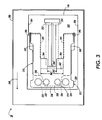
- the sheet stacking and lifting cassette tray assembly 28 includes a cassette tray frame 300 having a frame floor 302, frame side walls 304, 306 and a rear end wall 308.
- the sheet stacking and lifting cassette tray assembly 28 includes a selectable plurality, shown generally as 310, of sheet stacking and lifting subassemblies mounted within the cassette tray frame 300 for holding and efficiently lifting stacks of sheets 96 of different basis weight, or of different sizes and hence different weights.
- the plurality 310 of sheet stacking and lifting subassemblies may include a main sheet stacking and lifting subassembly 312, and at least one auxiliary sheet stacking and lifting subassembly 314.
- the main sheet stacking and lifting subassembly 312 includes a main stack supporting plate 320, and a first set of springs 322, 324 having a first spring rate R1, and connected to the cassette frame floor 302 and to the main stack supporting plate 320, for providing a first stack lifting force, and hence a first normal force F1 against the feedhead roll 102 ( Figure 1) for feeding sheets from such stack.
- the at least one auxiliary sheet stacking and lifting assembly 314 includes an auxiliary stack supporting plate 330.
- the auxiliary stack supporting plate 330 as shown, is located above the cassette frame floor 302, and below the stack supporting plate 320.
- the at least one auxiliary sheet stacking and lifting assembly 314 also includes a second set of springs 332, 334 that have a second spring rate R2 and are connected to the cassette frame floor 302 and to the auxiliary stack supporting plate 330, for providing an auxiliary stack lifting force F2 to the first stack lifting force F1 of the main sheet stacking and lifting subassembly 312 to lift a stack of sheets on the main stack supporting plate 320.
- the main and the at least one auxiliary sheet stacking and lifting assemblies 312, 314 thus together provide a compound and different normal force F3 (F1+F2) against the feedhead roll 102 for feeding sheets from a stack being lifted by both assemblies 312, 314.
- each of the main and the auxiliary stack supporting plates 320, 330 each has a front end 336, 338, respectively relative to a direction 340 of sheet feed, and each has rear end 342, 344 respectively.
- the rear end 342, 344 of each plate is mounted pivotably to each cassette frame side wall 304, 306, and preferably at a common pivot 346 on such wall.
- Their respective sets of springs 322, 324 and 332, 334 are connected to the front end 336, 338 respectively of each stack supporting plate 320, 330.
- the front end 336 of the main stack supporting plate 320 as shown ( Figure 3) is wider than that 338 of the at least one auxiliary stack supporting plate 330.
- This difference in width advantageously allows for the first set of springs 322, 324 of the main sheet stacking and lifting subassembly 312 to be located to the outside, on each side of the at least one auxiliary stack supporting plate 330.
- the second set of springs 332, 334 as connected to the front end 338 of the at least one auxiliary stack supporting plate 330, are therefore located to the inside, on each side, of the first set of springs 322, 324, thus allowing free up and down movement of the main sheet stacking and lifting subassembly 312, independently of the at least one auxiliary sheet stacking and lifting subassembly 314.
- the cassette frame floor 302 as shown importantly includes a slot 350 for slidably enabling movement of a sheet dimension adjusting guide, for example a sheet length guide 104 (Figure 1) for aligning sheets in a stack against the feedhead roll 102.
- a sheet dimension adjusting guide for example a sheet length guide 104 ( Figure 1) for aligning sheets in a stack against the feedhead roll 102.
- the slidable sheet length guide 104 acts advantageously as an automatic sheet lifting force selecting device for selecting, for example, between F1 and F3.
- the selecting device or sheet length guide 104 includes plate selection tabs 352, 354 formed thereon for riding over each side of the slot 350 as the device or sheet length guide 104 is moved back and forth through the slot 350.
- the cassette frame floor 302 also includes at least one stepped recess 356 having a depth at least equal to or greater than a thickness of the at least one sheet stack supporting plate 330, for receiving such plate 330, into a down and locked or held position ( Figure 5).
- the recess 356 as such also has an area (length x width) that is equal to or slightly greater than an area of the at least one auxiliary stack supporting plate 330, in order to provide an even stack supporting surface within the cassette frame 300, even when the auxiliary stack supporting plate 330 is being held down as above.
- the rear end 342 of the main stack supporting plate 320 includes a first center cutout 360 that is centered over the slot 350 for allowing the length guide 104 to move freely frontwards and backwards.
- the rear end 344 of the at least one auxiliary stack supporting plate 330 similarly includes a second center cutout 362 that is centered over the slot 350, and that is narrower than the first center cutout 360 of the main stack supporting plate 320.
- the module frame 26 for example of the auxiliary copy input module 24, importantly serves as a base portion for the machine 20, and provides a covered portion of the machine 20 at such base.
- the sheet stacking and lifting cassette tray assembly 28 thereof is slidably mounted to, and for movement into and out of, the module frame 26 so as to enable reloading of such cassette tray assembly with new and or different sheets of paper.
- the plurality 310 including the main and the at least one sheet stacking and lifting subassemblies 312, 314 (and comprising the main and auxiliary stack supporting plates 320, 330 and the sets of springs 322, 324, and 332, 334) are used for stacking and efficiently lifting a first type of sheets having a first basis weight, for example, long sheets such as letter size (8.5"x11") or legal size sheets (8.5"x14") of a given basis weight (e.g 20#).
- a first basis weight for example, long sheets such as letter size (8.5"x11") or legal size sheets (8.5"x14") of a given basis weight (e.g 20#).
- main stacking and lifting subassembly 312 (comprising the main stack supporting plate 320 and the first set of springs 322, 324) is used for efficiently lifting such a stack of short sheets having a different weight for the same number of sheets, or for the same stack height of sheets being fed.
- moving the length guide 104 from an 11 inch sheet length position ( Figure 4) into the 5.5 inch sheet length position ( Figure 5) causes the plate selection tabs 352, 354 to automatically ride over, engage and hold down the winged portions 362, 364 of the auxiliary stack supporting plate 330 along with the second set of springs 332, 334.
- this invention uses two selectable sheet stacking and lifting subassemblies 312, 314, each including a stack supporting plates 320, 330 and a set of springs 322, 324 and 332, 334 for efficiently lifting stacks of sheets.
- the invention essentially provides automatic optimization for at least two different type paper sizes in a forward buckle feeding type cassette tray assembly.
- the design is not limited to two plates and two sets of springs, since more, for example "n” plates and “n” sets of springs can be used in a similar fashion, depending on the number of different types of paper for which the feeder is to be optimized. Accordingly there will be “n” recesses in the floor 302 for receiving "n” stack supporting plates.
- the two different types of paper for which the present invention is optimized are 8.5" x 5.5", 20# paper to be fed long edge first, and 8.5" x 11", 20# paper to be fed short edge first.
- the top or main stack supporting plate 320 with its two supporting springs 322 and 324 were used alone or by themselves (by holding down the auxiliary plate 330 and its springs 332, 334) to lift the small paper, namely 8.5" x 5.5" against the feed rolls 102, therefore the springs used to accomplish this had a combined rate (R1) of 18.32 gms/mm.
- the bottom or auxiliary plate 330 with its two supporting springs 332, 334 were used to provide the additional support required to bring the sheet stacking and lifting cassette tray assembly 28 of the present invention spring rate (R1 + R2) to a value of 24.42 gms/mm, which then enabled the tray assembly 28 to feed the larger paper, namely 8.5" x 11".
- both stack supporting plates 320, 330 preferably are first locked in a down position in order to enable easy loading of the paper. Then the operator slides the length guide 104 forwardly until it touches the stack of sheets just loaded. If the paper or sheets just loaded are the small size, 8.5" x 5.5", the length guide 104 will be moved towards the front of the stack until it touches the stack of such short sheets.
- the tabs 352, 354 on the length guide 104 literally step over the auxiliary stack supporting plate 330, keeping it and its springs 332, 334 from being activated when the plates 320, 330 are released from the locked, down position.
- the main stack supporting plate 320 and its springs 322, 324 are allowed to move upwards and provide the required normal force F1 to the stack of short sheets ( Figure 5).
- the length guide 104 maintains the auxiliary plate 330 and its springs in the locked down position, thus keeping them from being actuated.
- a sheet cassette tray assembly having plural, selectable, force applying devices for applying and maintaining an effective sheet feeding normal force, on a stack of sheets, within a proper operating range for reliable feeding of plural types of sheets in such stacks, each type of sheet having a different size and basis weight.
- the plural, selectable force applying devices include a first plate and spring assembly, and a second plate and spring assembly.
- the plural, selectable force applying devices also include automatic selection means for automatically changing the sheet feeding normal force when the cassette tray assembly is adjusted for example from one size sheets to another by adjusting a sheet dimension guide in the cassette tray.
- the cassette tray assembly is optimized for more than one size type or more than one weight type of sheets.
- the cassette tray assembly as such thus can reliably and effectively increase the range of sheet sizes and basic paper weights for which the cassette tray operates reliably.
- the cassette tray as such can reliably handle greater than the conventional 250-sheet cassette volume without resort to costly elevator systems, or costly technical service adjustments.
- the sheet stacking and lifting cassette tray assembly includes a cassette frame including a frame floor, and frame side walls; a plurality of sheet stacking and lifting subassemblies mounted within, and to, the frame side walls for applying selectable values of sheet lifting normal forces against a sheet feedhead.
- Each sheet stacking and lifting subassembly of the plurality of sheet stacking and lifting subassemblies includes a pivotable stacking and supporting plate, and a set of springs having a spring rate for providing a normal force having a particular value for lifting a stack of sheets.
- the sheet stacking and lifting cassette tray assembly also includes a selecting device for engaging a first number of the plurality of sheet stacking and lifting subassemblies so as to prevent the first number of the plurality of sheet stacking and lifting subassemblies from applying a normal force for lifting, thus varying a number of the sheet stacking and lifting subassemblies applying a normal force to a stack of sheets of a given basis weight, and thereby enabling reliable and effective feeding of sheets from such stack without sheet feeding miscues.
Landscapes
- Physics & Mathematics (AREA)
- General Physics & Mathematics (AREA)
- Engineering & Computer Science (AREA)
- Mechanical Engineering (AREA)
- Sheets, Magazines, And Separation Thereof (AREA)
Applications Claiming Priority (2)
| Application Number | Priority Date | Filing Date | Title |
|---|---|---|---|
| US08/970,838 US5815787A (en) | 1997-11-14 | 1997-11-14 | Cassette tray assembly for feeding sheets of different basis weight |
| US970838 | 1997-11-14 |
Publications (3)
| Publication Number | Publication Date |
|---|---|
| EP0917009A2 true EP0917009A2 (fr) | 1999-05-19 |
| EP0917009A3 EP0917009A3 (fr) | 2000-01-12 |
| EP0917009B1 EP0917009B1 (fr) | 2003-07-30 |
Family
ID=25517585
Family Applications (1)
| Application Number | Title | Priority Date | Filing Date |
|---|---|---|---|
| EP98308939A Expired - Lifetime EP0917009B1 (fr) | 1997-11-14 | 1998-11-02 | Ensemble à cassette pour l'alimentation de feuilles de poids différents |
Country Status (5)
| Country | Link |
|---|---|
| US (1) | US5815787A (fr) |
| EP (1) | EP0917009B1 (fr) |
| JP (1) | JP3957416B2 (fr) |
| BR (1) | BR9804632B1 (fr) |
| DE (1) | DE69816757T2 (fr) |
Families Citing this family (23)
| Publication number | Priority date | Publication date | Assignee | Title |
|---|---|---|---|---|
| KR100258944B1 (ko) * | 1997-08-30 | 2000-06-15 | 윤종용 | 유니버설용지카세트 |
| KR100504032B1 (ko) * | 1997-11-04 | 2005-10-21 | 삼성전자주식회사 | 공기 완충식 댐퍼를 이용한 잉크젯 프린터의 자동급지장치 |
| JP3366597B2 (ja) * | 1999-08-06 | 2003-01-14 | 京セラミタ株式会社 | 用紙後端規制部材 |
| JP3736265B2 (ja) | 1999-08-23 | 2006-01-18 | ブラザー工業株式会社 | シート供給装置および画像形成装置 |
| JP4106883B2 (ja) * | 2000-10-12 | 2008-06-25 | コニカミノルタビジネステクノロジーズ株式会社 | 画像形成装置のプリントコントローラ並びに画像形成装置 |
| KR100412497B1 (ko) * | 2001-11-12 | 2003-12-31 | 삼성전자주식회사 | 프린팅기기의 용지 카세트 |
| JP4046649B2 (ja) * | 2003-06-10 | 2008-02-13 | 三洋電機株式会社 | 給紙トレイ |
| JP4415792B2 (ja) * | 2004-08-24 | 2010-02-17 | ブラザー工業株式会社 | 画像記録装置 |
| JP4353085B2 (ja) * | 2004-11-30 | 2009-10-28 | ブラザー工業株式会社 | 給紙カセット及び画像形成装置 |
| US7292796B2 (en) * | 2005-06-29 | 2007-11-06 | Xerox Corporation | Method and system for roller pair adjustment |
| US20070063423A1 (en) * | 2005-09-16 | 2007-03-22 | Kirby Alfred D | Media bed |
| USD556252S1 (en) * | 2006-03-17 | 2007-11-27 | Murata Kikai Kabushiki Kaisha | Paper feeder cassette |
| KR100754050B1 (ko) * | 2006-06-30 | 2007-08-31 | 노틸러스효성 주식회사 | 금융자동화기기의 지폐가이드장치 |
| JP4895047B2 (ja) * | 2007-12-28 | 2012-03-14 | ブラザー工業株式会社 | 給紙装置及びそれを備えた画像記録装置 |
| US20090206544A1 (en) * | 2008-02-18 | 2009-08-20 | Xerox Corporation | Preventing Overfill Of Media Sheets In a Sheet Feeder |
| JP5127570B2 (ja) * | 2008-05-29 | 2013-01-23 | キヤノン株式会社 | シート給送装置及び画像形成装置 |
| JP5219720B2 (ja) * | 2008-10-01 | 2013-06-26 | キヤノン株式会社 | シート給送装置及び画像形成装置 |
| JP5509761B2 (ja) * | 2009-09-18 | 2014-06-04 | 富士ゼロックス株式会社 | 搬送装置及び画像形成装置 |
| JP5759272B2 (ja) * | 2011-06-03 | 2015-08-05 | 株式会社沖データ | 媒体カセット及び画像形成装置 |
| JP5472650B2 (ja) * | 2011-06-16 | 2014-04-16 | コニカミノルタ株式会社 | 画像形成装置 |
| TWI517980B (zh) * | 2011-12-13 | 2016-01-21 | 金寶電子工業股份有限公司 | 事務機 |
| JP5652423B2 (ja) * | 2012-04-02 | 2015-01-14 | コニカミノルタ株式会社 | 画像形成装置 |
| US8870330B1 (en) * | 2013-04-12 | 2014-10-28 | Hewlett-Packard Development Company, L.P. | Printing system and method |
Family Cites Families (11)
| Publication number | Priority date | Publication date | Assignee | Title |
|---|---|---|---|---|
| JPS58152726A (ja) * | 1982-03-08 | 1983-09-10 | Ricoh Co Ltd | 給紙装置 |
| JPS59212327A (ja) * | 1983-05-13 | 1984-12-01 | Hitachi Ltd | 帳票の積載機構 |
| US4786042A (en) * | 1987-04-01 | 1988-11-22 | Xerox Corporation | Adjustable size sensing sheet cassette |
| US5085421A (en) * | 1991-03-04 | 1992-02-04 | Compaq Computer Corporation | Dual bin paper feed tray for an image reproduction machine such as a printer or copier |
| JPH0568975U (ja) * | 1992-02-27 | 1993-09-17 | 旭光学工業株式会社 | カセット収容記録紙の送りローラへの圧接構造 |
| JP3090169B2 (ja) * | 1992-09-07 | 2000-09-18 | キヤノン株式会社 | 給紙カセット |
| JP3285633B2 (ja) * | 1993-01-18 | 2002-05-27 | 沖電気工業株式会社 | 用紙カセット |
| JP3168127B2 (ja) * | 1993-11-24 | 2001-05-21 | キヤノン株式会社 | シート積載装置及び画像形成装置 |
| FR2726223A1 (fr) * | 1994-10-28 | 1996-05-03 | Canon Kk | Cassette de chargement de feuilles comportant une plaque elevatrice et un couvercle ayant une zone de poussee pour abaisser la plaque elevatrice |
| JPH0967028A (ja) * | 1995-09-01 | 1997-03-11 | Ricoh Co Ltd | 給紙装置 |
| JPH09267930A (ja) * | 1996-03-29 | 1997-10-14 | Ricoh Co Ltd | 給紙装置 |
-
1997
- 1997-11-14 US US08/970,838 patent/US5815787A/en not_active Expired - Lifetime
-
1998
- 1998-11-02 EP EP98308939A patent/EP0917009B1/fr not_active Expired - Lifetime
- 1998-11-02 DE DE69816757T patent/DE69816757T2/de not_active Expired - Lifetime
- 1998-11-05 JP JP31447998A patent/JP3957416B2/ja not_active Expired - Fee Related
- 1998-11-12 BR BRPI9804632-2A patent/BR9804632B1/pt not_active IP Right Cessation
Also Published As
| Publication number | Publication date |
|---|---|
| DE69816757D1 (de) | 2003-09-04 |
| JPH11199064A (ja) | 1999-07-27 |
| BR9804632B1 (pt) | 2012-02-22 |
| US5815787A (en) | 1998-09-29 |
| EP0917009A3 (fr) | 2000-01-12 |
| JP3957416B2 (ja) | 2007-08-15 |
| DE69816757T2 (de) | 2004-05-27 |
| BR9804632A (pt) | 1999-11-03 |
| EP0917009B1 (fr) | 2003-07-30 |
Similar Documents
| Publication | Publication Date | Title |
|---|---|---|
| EP0917009B1 (fr) | Ensemble à cassette pour l'alimentation de feuilles de poids différents | |
| EP0990956B1 (fr) | Appareil de réception et d'empilage 1-N et N-1 de feuilles séparées | |
| KR101161998B1 (ko) | 시트 급송 장치 및 화상 형성 장치 | |
| US6409165B1 (en) | Sheet holder and sheet trailing edge restriction member therefor | |
| JP2602816B2 (ja) | プリンター装置およびプリンター装置用の汎用シート給送装置 | |
| US5320338A (en) | Cassette | |
| US7533880B2 (en) | Sheet feeding device and image forming apparatus | |
| EP1708040B1 (fr) | Appareil de formation d'images | |
| EP0296820B1 (fr) | Appareil d'avancement de feuilles | |
| US5215299A (en) | Spring elevator system for paper supply | |
| CA2188195C (fr) | Machine reprographique a support a cassettes de grande capacite | |
| JPH09183522A (ja) | シートカセット及び画像形成装置 | |
| US5695184A (en) | Document production machine having a high capacity, high reliability cassette tray sheet feeding assembly | |
| MXPA98008637A (en) | Assembly of cassette tray for feeding leaves of different weight b | |
| JP4965417B2 (ja) | 画像形成装置 | |
| JP2005189309A (ja) | 画像形成装置 | |
| JPH0971327A (ja) | シート積載装置及び画像形成装置 | |
| JP7415416B2 (ja) | 媒体供給装置及びこれを用いた処理装置並びに位置拘束治具 | |
| JP2606307B2 (ja) | 画像形成装置の給紙装置 | |
| JP2001063836A (ja) | シート供給装置および画像形成装置 | |
| JP2012001354A (ja) | 給紙装置およびこれを備えた画像形成装置 | |
| JPH07291463A (ja) | シート積載装置及び画像形成装置 | |
| JPH04303333A (ja) | 給紙カセット | |
| JP2003089436A (ja) | 給紙カセット | |
| JP2005178999A (ja) | 給紙装置および画像形成装置 |
Legal Events
| Date | Code | Title | Description |
|---|---|---|---|
| PUAI | Public reference made under article 153(3) epc to a published international application that has entered the european phase |
Free format text: ORIGINAL CODE: 0009012 |
|
| AK | Designated contracting states |
Kind code of ref document: A2 Designated state(s): DE FR GB |
|
| AX | Request for extension of the european patent |
Free format text: AL;LT;LV;MK;RO;SI |
|
| PUAL | Search report despatched |
Free format text: ORIGINAL CODE: 0009013 |
|
| AK | Designated contracting states |
Kind code of ref document: A3 Designated state(s): AT BE CH CY DE DK ES FI FR GB GR IE IT LI LU MC NL PT SE |
|
| AX | Request for extension of the european patent |
Free format text: AL;LT;LV;MK;RO;SI |
|
| 17P | Request for examination filed |
Effective date: 20000712 |
|
| AKX | Designation fees paid |
Free format text: DE FR GB |
|
| 17Q | First examination report despatched |
Effective date: 20020115 |
|
| GRAH | Despatch of communication of intention to grant a patent |
Free format text: ORIGINAL CODE: EPIDOS IGRA |
|
| GRAH | Despatch of communication of intention to grant a patent |
Free format text: ORIGINAL CODE: EPIDOS IGRA |
|
| GRAA | (expected) grant |
Free format text: ORIGINAL CODE: 0009210 |
|
| AK | Designated contracting states |
Designated state(s): DE FR GB |
|
| REG | Reference to a national code |
Ref country code: GB Ref legal event code: FG4D |
|
| REF | Corresponds to: |
Ref document number: 69816757 Country of ref document: DE Date of ref document: 20030904 Kind code of ref document: P |
|
| ET | Fr: translation filed | ||
| PLBE | No opposition filed within time limit |
Free format text: ORIGINAL CODE: 0009261 |
|
| STAA | Information on the status of an ep patent application or granted ep patent |
Free format text: STATUS: NO OPPOSITION FILED WITHIN TIME LIMIT |
|
| 26N | No opposition filed |
Effective date: 20040504 |
|
| REG | Reference to a national code |
Ref country code: GB Ref legal event code: 746 Effective date: 20050809 |
|
| REG | Reference to a national code |
Ref country code: FR Ref legal event code: PLFP Year of fee payment: 18 |
|
| PGFP | Annual fee paid to national office [announced via postgrant information from national office to epo] |
Ref country code: GB Payment date: 20151027 Year of fee payment: 18 Ref country code: DE Payment date: 20151022 Year of fee payment: 18 |
|
| PGFP | Annual fee paid to national office [announced via postgrant information from national office to epo] |
Ref country code: FR Payment date: 20151023 Year of fee payment: 18 |
|
| REG | Reference to a national code |
Ref country code: DE Ref legal event code: R119 Ref document number: 69816757 Country of ref document: DE |
|
| GBPC | Gb: european patent ceased through non-payment of renewal fee |
Effective date: 20161102 |
|
| REG | Reference to a national code |
Ref country code: FR Ref legal event code: ST Effective date: 20170731 |
|
| PG25 | Lapsed in a contracting state [announced via postgrant information from national office to epo] |
Ref country code: FR Free format text: LAPSE BECAUSE OF NON-PAYMENT OF DUE FEES Effective date: 20161130 |
|
| PG25 | Lapsed in a contracting state [announced via postgrant information from national office to epo] |
Ref country code: DE Free format text: LAPSE BECAUSE OF NON-PAYMENT OF DUE FEES Effective date: 20170601 Ref country code: GB Free format text: LAPSE BECAUSE OF NON-PAYMENT OF DUE FEES Effective date: 20161102 |