EP0917013A2 - Bilderzeugungsgerät - Google Patents
Bilderzeugungsgerät Download PDFInfo
- Publication number
- EP0917013A2 EP0917013A2 EP98121700A EP98121700A EP0917013A2 EP 0917013 A2 EP0917013 A2 EP 0917013A2 EP 98121700 A EP98121700 A EP 98121700A EP 98121700 A EP98121700 A EP 98121700A EP 0917013 A2 EP0917013 A2 EP 0917013A2
- Authority
- EP
- European Patent Office
- Prior art keywords
- image
- transfer
- transfer material
- toner
- image formation
- Prior art date
- Legal status (The legal status is an assumption and is not a legal conclusion. Google has not performed a legal analysis and makes no representation as to the accuracy of the status listed.)
- Granted
Links
- 230000015572 biosynthetic process Effects 0.000 title claims abstract description 60
- 238000012546 transfer Methods 0.000 claims abstract description 198
- 239000000463 material Substances 0.000 claims abstract description 88
- 238000000926 separation method Methods 0.000 claims abstract description 73
- 238000011161 development Methods 0.000 claims abstract description 64
- 239000000853 adhesive Substances 0.000 claims abstract description 4
- 230000001070 adhesive effect Effects 0.000 claims abstract description 4
- 238000001514 detection method Methods 0.000 claims description 8
- 238000012986 modification Methods 0.000 claims description 3
- 230000004048 modification Effects 0.000 claims description 3
- 230000002950 deficient Effects 0.000 abstract description 28
- 230000000994 depressogenic effect Effects 0.000 description 14
- 238000012423 maintenance Methods 0.000 description 13
- 238000000034 method Methods 0.000 description 12
- 230000008030 elimination Effects 0.000 description 7
- 238000003379 elimination reaction Methods 0.000 description 7
- 230000006870 function Effects 0.000 description 5
- 230000008569 process Effects 0.000 description 5
- 230000007613 environmental effect Effects 0.000 description 4
- 238000001179 sorption measurement Methods 0.000 description 4
- 230000008859 change Effects 0.000 description 3
- 238000004140 cleaning Methods 0.000 description 3
- 238000010586 diagram Methods 0.000 description 3
- 230000000694 effects Effects 0.000 description 3
- 230000002349 favourable effect Effects 0.000 description 3
- 238000003780 insertion Methods 0.000 description 3
- 230000037431 insertion Effects 0.000 description 3
- 238000009434 installation Methods 0.000 description 3
- 230000009467 reduction Effects 0.000 description 3
- 206010047571 Visual impairment Diseases 0.000 description 2
- 238000010438 heat treatment Methods 0.000 description 2
- 238000005286 illumination Methods 0.000 description 2
- 230000000977 initiatory effect Effects 0.000 description 2
- 230000003287 optical effect Effects 0.000 description 2
- 230000005856 abnormality Effects 0.000 description 1
- 238000010521 absorption reaction Methods 0.000 description 1
- 238000013459 approach Methods 0.000 description 1
- 230000002238 attenuated effect Effects 0.000 description 1
- 238000007796 conventional method Methods 0.000 description 1
- 238000012937 correction Methods 0.000 description 1
- 239000011521 glass Substances 0.000 description 1
- 239000004973 liquid crystal related substance Substances 0.000 description 1
- 238000004519 manufacturing process Methods 0.000 description 1
- 238000005259 measurement Methods 0.000 description 1
- 239000000203 mixture Substances 0.000 description 1
- 239000002245 particle Substances 0.000 description 1
- 238000011160 research Methods 0.000 description 1
- 239000011347 resin Substances 0.000 description 1
- 229920005989 resin Polymers 0.000 description 1
- 230000004044 response Effects 0.000 description 1
- 230000000717 retained effect Effects 0.000 description 1
- 230000001020 rhythmical effect Effects 0.000 description 1
- 238000004513 sizing Methods 0.000 description 1
- 125000006850 spacer group Chemical group 0.000 description 1
- 239000013589 supplement Substances 0.000 description 1
- 239000000725 suspension Substances 0.000 description 1
Images


Classifications
-
- G—PHYSICS
- G03—PHOTOGRAPHY; CINEMATOGRAPHY; ANALOGOUS TECHNIQUES USING WAVES OTHER THAN OPTICAL WAVES; ELECTROGRAPHY; HOLOGRAPHY
- G03G—ELECTROGRAPHY; ELECTROPHOTOGRAPHY; MAGNETOGRAPHY
- G03G15/00—Apparatus for electrographic processes using a charge pattern
- G03G15/06—Apparatus for electrographic processes using a charge pattern for developing
- G03G15/065—Arrangements for controlling the potential of the developing electrode
-
- G—PHYSICS
- G03—PHOTOGRAPHY; CINEMATOGRAPHY; ANALOGOUS TECHNIQUES USING WAVES OTHER THAN OPTICAL WAVES; ELECTROGRAPHY; HOLOGRAPHY
- G03G—ELECTROGRAPHY; ELECTROPHOTOGRAPHY; MAGNETOGRAPHY
- G03G2215/00—Apparatus for electrophotographic processes
- G03G2215/00025—Machine control, e.g. regulating different parts of the machine
- G03G2215/00071—Machine control, e.g. regulating different parts of the machine by measuring the photoconductor or its environmental characteristics
- G03G2215/00084—Machine control, e.g. regulating different parts of the machine by measuring the photoconductor or its environmental characteristics the characteristic being the temperature
-
- G—PHYSICS
- G03—PHOTOGRAPHY; CINEMATOGRAPHY; ANALOGOUS TECHNIQUES USING WAVES OTHER THAN OPTICAL WAVES; ELECTROGRAPHY; HOLOGRAPHY
- G03G—ELECTROGRAPHY; ELECTROPHOTOGRAPHY; MAGNETOGRAPHY
- G03G2215/00—Apparatus for electrophotographic processes
- G03G2215/00362—Apparatus for electrophotographic processes relating to the copy medium handling
- G03G2215/00535—Stable handling of copy medium
- G03G2215/00556—Control of copy medium feeding
- G03G2215/00586—Control of copy medium feeding duplex mode
Definitions
- the present invention relates to an image formation apparatus, such as a copying machine, a laser beam printer. More particularly, the invention relates to an image formation apparatus provided with developing means for developing by use of developer the electrostatic images which are formed on an image bearing member, and also, provided with separation means for separating a transfer material from the image bearing member.
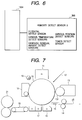
- Fig. 7 is a view which schematically shows one example of the conventional image formation apparatus described above.
- the surface of an image bearing member (photosensitive device) 10 is charged uniformly by means of the primary charger 11 which is formed by corona charging device.
- the image exposure 12 is given in accordance with the image information by use of the laser scanner or some other image exposure device (not shown).
- the electrostatic latent images are formed on the surface of image bearing member 10 corresponding to the image information.
- the image exposure 12 is of the type that light is irradiated to the darker (black) portion of the images.
- the electrostatic latent images formed on the surface of the image bearing member 10 are developed into the toner images by use of the development device 13.
- the developer that contains at least toner is filled in it, and with the rotations of an agitator (not shown), a developer bearing member 131 that conveys toner to the surface of the toner image bearing member 10.
- the toner is then charged to a specific polarity by means of friction charging.
- the timing roller 14 and the transfer guide 15 form transfer material convey means.
- the transfer material 25 which has been fed by a feeding device (not shown)
- the transfer device 16 which is formed by the corona charger, gives to the back face of the transfer material 25 the charge having the reverse polarity of the toner.
- the transfer material 25 gives to the back face of the transfer material 25 the charge having the reverse polarity of the toner.
- the transfer material 25 is adsorbed electrostatically to the surface of the image bearing member 10 due to the charge given to the back face thereof. Therefore, by use of the separation device 17, the charge, which is provided in the transfer process, is partly removed to reduce the adsorption between the transfer material 25 and the image bearing member 10 in order to separate the transfer material 25 from the image bearing member 10 by the utilization of the elasticity of the transfer material 25.
- the separation device 17 is the corona charger that gives the charge having the reverse polarity of the charge given by the transfer device 16 or the one to which AC current is superposed. After a transfer process of the kind, the charge given to the back face of the transfer material is removed to weaken the electrostatic adsorption force between the image bearing member and the transfer material. Then, the transfer material is separated by means of the elasticity of the transfer material. This method is called "the electrostatic separation".
- the toner images on the transfer material 25 are fixed to it by use of the fixation device 21.
- the transfer material having the toner images thus transferred to it is exhausted by use of the exhaust roller.
- the transfer material is retained in an intermediate tray in the apparatus, and after that, it is again fed and conveyed to the transfer device for the transfer of the toner images to the transfer material which is separated by use of the separation device 17. It is then exhausted outside the apparatus after the fixation has been made by the fixation device 21.
- the cleaning device 18 cleans and removes the slightly remaining toner on the surface of the image bearing member 10 after the toner images have been transferred to the transfer material 25. Then, the electrostatic latent images are removed by means of pre-exposure light 19. In this manner, the next image formation cycle will be performed.
- the separation performance becomes instable due to the difference in the elastic properties (rigidity) of transfer materials.
- the elastic properties (rigidity) of transfer materials For example, by the changes of moisture content in the transfer material, the elasticity thereof changes accordingly. Therefore, if the image formation apparatus is used under a highly humid environment, the moisture content of the transfer material is increased to make its elasticity smaller. In this case, the separation errors may take place. Also, if the kinds of transfer material differ in the thickness thereof or the like, the separation performance may be affected to vary in some cases.
- a transfer material exhausted from the fixation device is curled by the application of heat, and if the curling is directed so that it is wound around the image bearing member in case of a multiple transfer, the defective separation or re-transfer may take place in some cases.
- the separation capability changes depending on the print ratio of images on the head portion of the transfer material that should be conveyed, and if the print ratio on such portion is low, the defective separation tends to take place.
- a gap may take place to weaken the close contactness between them, hence the separation becoming easier.
- the gap between the transfer material and the image bearing member becomes extremely small, thus creating a condition that makes the separation extremely difficult.
- the print ratio on the leading end and the trailing end of the transfer material may exert a significant influence on curling.
- the curling becomes greater, and the print ratio of the first face exerts influence on the separation capability of the second face eventually.
- the separation capability changes greatly even for the same white images depending on the variation of the amount of toner adhesion which may be present slightly on the white background (background portion) of such image (hereinafter, referred to as "fogging toner").
- the toner amount is small, the fogging toner has a great effect on the electrostatic adsorption to be effectuated between the image bearing member and the transfer material after the transfer process.
- the image formation apparatus is not in use for a long time at night or over the week end, the charge that has been given to the toner in the development device by the friction charging is attenuated.
- the development device does not gain its developing characteristics good enough for a while when the image formation apparatus is used again after its operation is at rest for a long time.
- the amount of fogging toner is also made smaller accordingly. In other words, the defective separation may take place more often when the image formation apparatus is used after a long rest.
- the de-electrifying capability of the separation device is made larger, the electric charge given to the back face of the transfer material (the charge having the reverse polarity of the toner image) is reduced. As a result, the electrostatic adsorption between the transfer material and the surface of the image bearing member is weakened accordingly. Therefore, although the separation of the transfer material becomes possible, the holding power of the charge given to the back face of the transfer material is reduced. Then, there occurs the phenomenon that the toner image once transferred to the transfer material is again attracted and taken away to the electrostatic latent image formed on the surface of the image bearing member on the moment the transfer material is separated from the surface of the image bearing member. Such phenomenon as this is referred to as "re-transfer". If the re-transfer takes place, the density of the output image is made extremely lower, and the image quality is also degraded significantly after all.
- the first object of the present invention to provide an image formation apparatus capable of preventing the defective separation and the re-transfer.
- an image formation apparatus of the present invention comprises an image bearing member; developing means for developing by use of toner the electrostatic image formed on the image bearing member; transfer charging means for transferring the toner image from the image bearing member to a transfer material in the transfer position; and separation means for de-electrifying the transfer material for separating the transfer material from the image bearing member.
- modifying means is further provided for modifying the development conditions in accordance with the states of the toner image formed on the transfer material, and modifying the adhesive amount of fogging toner adhering to the image background of the toner image on the image bearing member.
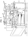
- Fig. 1 is a cross-sectional view which shows an image formation apparatus, in which the image formation apparatus is provided with the main body of a copying device 100, a circulating type automatic feeding device of source documents, that is, a feeder (hereinafter referred to as "RDF") 200, and a sorter 250.
- RDF circulating type automatic feeding device of source documents
- sorter 250 it is possible to use the RDF 200 and the sorter 250 by freely combining them with respect to the main body 100.
- the main body 100 comprises a source document glass stand (a source document stacker) 101; an optical system (image reading means) 102; a source document illuminating lamp (an exposure lamp) 103; a scanning mirror; a lens 143; a motor 104; and others.
- a source document is illuminated by the exposure lamp 103 which scans the source document by use of the motor 104. Then, the reflection light from the source document is irradiated to a photosensitive drum 105 by the scanning mirror and the lens.
- a primary charger 106 Around the photosensitive drum 105, arranged are a primary charger 106, a blank exposure unit 107; a potential sensor 108; a developing device 109; a transfer charger 110; a separation charger 111; and a cleaning device 112. With these members and the photosensitive drum 105 and others, image recording means is structured.
- the photosensitive drum 105 rotates in the direction indicated by an arrow in Fig. 1 by the main motor 113, and corona charger is applied to it by use of the primary charger 106. Then, when the reflection light form a source document is irradiated by the optical system 102, the electrostatic latent image is formed thereon. The electrostatic latent image is made visible as the toner image when developed by means of the developing device 109. On the other hand, the transfer sheet is conveyed into the interior of the main body 100 by feed roller 118 or 119 either from the upper cassette 114 or the lower cassette 115 by use of the pickup roller 116 or 117.
- the transfer charger 110 by means of the transfer charger 110, the toner image is transferred.
- the voltage which has the reverse polarity of the charging polarity of the toner image is applied to the transfer charger 110.
- the back face of the transfer material is then charged with the reverse polarity of the charging polarity of the toner image.
- the transfer sheet is separated from the photosensitive drum 106 by use of the separation charger 111, and guided to the fixing device 122 by the convey belt 121 for its fixation to be made by the application of heat under pressure. Subsequently, the fixed transfer sheet is exhausted by the exhaust roller 123 outside the main body 100.
- the separation charger 111 applied is the DC voltage provided with the polarity opposite to that of the voltage applied to the transfer charger or the DC voltage of the kind which is superposed with AC voltage, hence partly de-electrifying the transfer charge applied to the back face of the transfer material after the transfer has been performed. Also, the surface of the photosensitive drum 105 is cleaned off by means of the cleaning device 112.
- a paper deck 124 is provided so as to store 4,000 transfer sheets, for example.
- the lifter 125 is arranged to be elevated corresponding to the amount of stored transfer sheets so that the transfer sheet is always in contact with the feed roller 126.
- This apparatus is provided with the both-face mode in which after images are formed on one face of a transfer material, images are formed on the other face thereof, and also, provided with the multiple mode in which after images are formed on one face of the transfer material, other images are formed on the same face thereof.
- the exhaust sheet flapper 127 switches the passage of the transfer sheet on the both-face recording side or the multiple recording side, and that of the exhaust (the sorter 250) side.
- the transfer sheet fed out from the exhaust roller 123 is directed either to the both-face recording side or to the multiple recording side by this exhaust sheet flapper 127.
- the lower convey path 128 enables the front/rear face of transfer sheet fed out from the exhaust roller 123 to be reversed through the reversing path 129, and guided to the re-feed tray 130.
- the transfer sheet is guided directly to the lower convey path 128 without the intervention of the reversing path 129.
- the feed roller 132 feeds the transfer sheet to the photosensitive drum 105 side through the passage 133.
- the exhaust roller 134 is arranged in the vicinity of the exhaust sheet flapper 127, and the transfer sheet is exhausted outside the apparatus if the exhaust sheet flapper 127 is switched over to the exhaust side.
- the exhaust sheet flapper 127 is brought up to store the copied transfer sheet in the re-feed tray 130 in the reversed condition obtainable through the convey paths 128 and 129.
- the multiple flapper 131 is brought down in the right-hand direction.
- the multiple flapper 131 is brought down in the left-hand direction.
- the transfer sheet stored in the re-feed tray 130 is guided one and one by means of the feed roller 132 to the regist roller 120 of the main body through the passage 133.
- the exhaust sheet flapper 127 is brought up so that the flapper 131 is brought down in the right-hand direction.
- the copied transfer sheet is conveyed to the convey path 129 side.
- the reversing roller 142 is conveyed by means of the reversing roller 142 to the second feed roller side.
- the exhaust roller 134 the transfer sheet is exhausted outside the apparatus in a posture that it has been reversed.
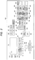
- Fig. 2 is a view which shows the structural example of the operation unit 600 arranged for the main body 100.
- the key 601 marked with an asterisk (*) is used by the operator (user) when he selects a mode such as to set the binding margin; to set the size in which to eliminate the frame of an original document, or the like.
- the cursor key 627 is used when selecting each item of the mode to be set.
- the OK key 628 is used to establish the content of each setting in the mode thus selected.
- the all reset key 606 is depressed when the selected mode should be returned to the standard mode, and also, when the automatic shut off status should be returned to the standard mode.
- the copy initiation key (copy start key) 605 is depressed to begin copying.
- the clear/stop key 604 is provided with the function of a clear key in the standby status, and the function of a stop key during the copy recording.
- the clear key is also usable when releasing the currently set number of copying sheets. Also, the stop key is depressed to suspend the continuous copying.
- the ten keys 603 are used for setting the number of copying sheets, and also, for setting the respective * (asterisk) modes.
- the memory key 619 is used for registering in advance the copying mode that the user often operates, and also, used for setting the mode whereby to call the registered copying mode.
- the copy density keys 611 and 612 are depressed if the copy density should be adjusted manually.
- the AE key 613 is depressed when the copy density should be adjusted automatically corresponding to that of the source document to be copied or it is depressed to release the AE (automatic density adjustment) and to switch it over to the manual adjustment.
- the copy sheet selection key 124 is depressed when selecting the upper paper lift 119, the lower paper lifter 115, the paper deck 124, or the multiple manual insertion 150.
- the equivalent key 610 is depressed when the copy is made in the same size (actual measurement) of a source document.
- the automatic sizing key 616 is depressed to automatically designate the reduction or enlargement of the image on a source document so that it is in agreement with the size of a transfer sheet to be designated.
- the both face key 626 is depressed when the both face copying is made from a one face source document; when the both face copying is made from a both face source document; or when the one face copying is made from a both face source document.
- With the binding margin key 625 it is possible to form a binding margin on the left side of a transfer sheet in a designated length.
- the photographing key 624 is depressed to copy a photographic source document.
- the multiple key 623 is depressed to form (synthesize) one image on the same face of a transfer sheet from two source documents.
- the source document frame elimination key 620 is depressed when the user intends to eliminate the frame of a specifically sized source document. In this case, the size of the corresponding source document is set by use of the asterisk key 601.
- the sheet frame elimination key 621 is depressed when the frame of a sheet (transfer sheet) should be eliminated in order to match it with the size of a copying sheet (transfer sheet).
- the front page mode setting key 629 is used for the production of a front sheet, a back face sheet, and an insertion sheet (such as to insert a different kind of transfer material (colored sheet) between white sheets).
- the page continuation copy key 630 is used when the left and right pages of a spread book is copied continuously.
- the exhaust selection key 614 is used for the selection of the exhaust methods using the staple sort, sort, and group sort. It is also used to select the staple mode, the sort mode, and the group mode or to release the selected mode for the sheet after recording with the staple sorter being connected.
- the reservation key 631 is used when beginning the copy mode setting for the reserved source document stacked on the reservation tray 210. Also, it is used when releasing the reserved setting.
- the slight reduction key 632 is used when the slight reduction mode is applied in order to make the designated copying magnification slightly smaller.
- the guide key 633 is used to indicate the explanation of each function of various keys on the screen of the message display.
- the message display 701 is LCD (liquid crystal display) type that indicates on its screen the information (characters and graphics) related to the copying operations. For example, the display 701 indicates on its screen the number of copies designated by use of the ten keys 603; the copying magnifications set by use of the keys 608 and 609 to change the specific sizes, the key 610 to obtain the same size, and the keys 617 and 618 for zooming use; the size of sheet to be used, which is selected by use of the sheet selection key 607; the messages to indicate the current status of the main body 100 of the copying device; the guide messages to indicate the operational procedures; and other information, such as the contents set for each of the modes.
- LCD liquid crystal display
- the AE indication device 704 is illuminated when the AE (automatic density adjustment) is selected by use of the AE key 613.
- the pre-heating indication device 709 is illuminated when the apparatus is still in the state of pre-heating.
- the levels of operational setting are classified and arranged in accordance with the knowledge and experience of the users, such as the standard that may be applicable to the general user, the supervisory user, or to the maintenance supervisory user, and the like, respectively. (For example, the operation levels are set by use of identification numbers accordingly). More precisely, the specific level of operation is ready to use.
- the general user is able to operate the apparatus at the level suitable for him; by use of the specific ID number plus the * key, the supervisory user is able to operate the apparatus at the level suitable for him; and by use of the specific ID number plus the rhythmical inputs of several specific keys or the like, the maintenance supervisory user is ready to execute his level of operation.
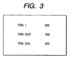
- Fig. 3 is a view which shows the example of the display screen of the LCD 700 indicating a part of the items of the setting changes that the maintenance supervisory user may make with respect to the transfer separation in the mode that he can set.
- the TRN 500 is for the intensity of transfer and 500 is the target value of the intensity thereof.
- the maintenance supervisory user can adjust them in accordance with the condition in which the user operates the apparatus.
- Fig. 4 is a block diagram showing the control system of the image formation apparatus embodying the present invention, in which the control circuit (controller) 1004 comprises the CPU 1004a, ROM 1004b, and RAM 1004c, and others, and performs the overall control of the copying sequence in accordance with the program stored in the ROM 1004b.
- the control circuit (controller) 1004 comprises the CPU 1004a, ROM 1004b, and RAM 1004c, and others, and performs the overall control of the copying sequence in accordance with the program stored in the ROM 1004b.
- the key input unit such as the copy mode set up keys (such as one face, both face, multiple mode, copy magnifications, cassette selections), the ten keys to set the number of copying sheets, the start key to instruct the initiation of a copy operation, the stop key to instruct the suspension of the copy operation, the reset key to enable the current operation mode to return to the standard one, as well as the indication unit, such as LED and LCD, which indicate the current status of operation mode or the like.
- the copy mode set up keys such as one face, both face, multiple mode, copy magnifications, cassette selections
- the ten keys to set the number of copying sheets
- the start key to instruct the initiation of a copy operation
- the stop key to instruct the suspension of the copy operation
- the reset key to enable the current operation mode to return to the standard one
- the indication unit such as LED and LCD, which indicate the current status of operation mode or the like.
- the thermistor 302 detects the surface temperature of the fixing roller 144. Then, the value which is A/D converted by the A/D converter 301 is inputted into the controller 1004. In accordance with the detected value of the thermistor 302, the controller 1004 controls the surface temperature of the fixing roller 144 so that it is at the predetermined value.
- the high-voltage control unit 303 controls the high-voltage unit 304 that applies the predetermined potential to the charging system, such as the primary charger 106, the transfer charger 110, as well as applies it to the development device 109 and the like.
- the motor control unit 295 controls the driving of motors 306, such as the respective stepping motors, the main driving motor.
- the DC load control unit 307 controls the solenoids used for the pickup roller 116 and others, the clutches used for the resist roller 120 and others, and the driving of fans and the like.
- the outputs of various sensors are inputted into the controller 1004.
- the AC driver 1000 controls the AC loads to the source document illumination lamp 103 and others, and also, controls the AC supply-source of the fixing heater 310.
- this driver detects the abnormality of the source document illumination lamp 103, the fixing heater 311, and others. Then it turns off the main switch 1001 which is provided with the shut off function. Further, the AC inputs before and after the main switch 1001 are switched over by the controller 1004 to be inputted into the power-supply source 1100.
- the power-supply source 1100 supplies DC power for use of the controller 1004 and the like. Then, at the same time that AC power is inputted from the AC driver 1000, the AC power is inputted from the input power plug 311 to the power-supply source 1100 through the main switch 1001 and the door switch 1007.
- the paper deck 124 is the sheet feeding device to deal with the stacked transfer sheets.
- the feeder 200 is the automatic source document convey device to set the plural numbers of source documents automatically.
- the sorter 250 is the sorting device to sort the transfer sheets to be exhausted.
- the high-voltage unit 304 will be described a little more in detail in conjunction with Fig. 5.
- the high-voltage unit 304 comprises the high-voltage DC generator 3041 for primary use; the high-voltage DC generator 3042 for use of supply to the transfer charger; the high-voltage AC plus DC generator 3043 for separation use; the high-voltage AC plus DC generator 3044 for use of the post charger; and the development bias high-voltage generator 3045.
- the development bias there are used the rectangular wave, the wave whose duty ratio has changed, the sine wave, as well as the alternating field which is called slope bias. Then, these having some DC component superposed on them are used as the development bias.
- the frequencies thereof are selected within a range of 1,000 Hz to several thousands Hz depending on the apparatus to be used and the characteristics of toner to be used.
- the present embodiment is arranged to switch over the development bias generators having the two kinds of slope bias waveforms, each at 2,700 Hz and 2,000 Hz, in accordance with the corresponding signals from the controller 1004.
- the slope bias waveforms are those in the form of a trapezoid with the flat peak portion of a triangular wave.
- the Table 1 shows the relationship between the levels of the defective separation re-transfer, and the copy mode, the environmental condition, and the paper conditions.
- Development bias 2,700 Hz Environment Paper condition Mode Curled direction Fogging Defective separation retransfer level Low humidity 5% Immediately after unpacked One face None Slightly large ⁇ 1-1 Both face Downwardly curled Slightly large ⁇ 1-2 Multiple Upwardly curled Slightly large ⁇ 1-3 Normal humidity 50% One face None Normal ⁇ 1-4 Both face Downwardly curled Normal ⁇ 1-5 Multiple Upwardly curled Normal ⁇ 1-6 High humidity 80% One face None Extreamely small ⁇ 1-7 Both face Downwardly curled Extreamely small ⁇ 1-8 Multiple Upwardly curled Extreamely small X 1-9 Extremely high humidity 90% One face None Almost none ⁇ 1-10 Both face Downwardly curled Almost none ⁇ 1-11 Multiple Upwardly curled Almost none X 1-12 Low humidity 5% Paper left intact One face None Slightly large ⁇ 1-1
- the level X of the defective separation re-transfer indicates that there is no optimal region (that is, the optimal latitude) between the defective separation and the re-transfer.
- the optimal setting value of the separation current is caused to vary depending on the environmental conditions.
- the X level indicated on the Table 1 here such as having been described above.
- the mark ⁇ indicates that the optimal latitude is considerably narrow, but it is still usable.
- the mark ⁇ indicates that the optimal latitude is wide.
- the Table 1 deals with the case where the development bias is used with the provision of the AC voltage of 2,700 Hz, and shows the environment under which the apparatus is left intact; the paper condition; the fogging conditions in the development device; and the modes, as well as the curled conditions. Then, the resultant detective separation and re-transfer levels are listed with respect to these conditions.
- the fogging toner is the one unstably charged, such as having a smaller charge amount than that of the regular toner or the reverse polarity of the electrostatic charge of the regular toner, and the fogging toner often adheres to the background (white part) of the portion where the regular toner adheres on the photosensitive device.
- the fogging toner is present in a slightly larger quantity in the development device in the lower humid environment, and it is made increasingly smaller as the humidity becomes higher.
- This fogging toner functions as spacer particles that form a gap between the photosensitive drum and the paper sheet. Therefore, the more the fogging toner is available, the wider becomes the optimal latitude of the separation.
- the availability of fogging toner exerts the significant influence on the separation capability as it approaches the condition where such toner is almost none.
- its effect on the enhancement of the separation capability is no longer conspicuous even if the quantity of the fogging toner is increased more after it has once reached a certain level of increase.
- the quantity of the fogging toner is smaller in the extremely humid and high humid environments. In such a case, if the modification is made so as to increase the quantity of fogging toner, it should demonstrate a significant effect on the enhancement of separation.
- the term “upwardly curled” means the curling which is directed to wind around the photosensitive drum at the time of re-transfer separation.
- the term “downwardly curled” means the curling which is directed the other way around. Then, when the upward curling takes place, the optimal latitude of the separation is made extremely narrower. Therefore, for the separation, the downward curling is favorable.
- the upward or downward curling occurs without exception when the general fixation equipment is used for fixing toner images by the application of heat. In many cases, the curling takes place in the opposite directions for the transfer effectuated for the both face or multiple image pass. Also, the property of paper changes greatly depending on whether it is dried or moisture-laden. Then, the curling directions are opposite to each other.
- the curl is removed or corrected by curl correction means after fixation.
- care is more often given to the both face mode which is usually used, and the resultant curling is downward to make the separation easier. Under the circumstance, therefore, the multiple mode produces the upward curling.
- the curling direction is reversed (compare 1-23, 1-24 with 1-11, 1-12 or compare 1-14 with 1-15). In other words, if the paper is moisture-laden extremely, curling cannot be corrected, and its direction becomes reversed.
- the level of the defective separation and re-transfer becomes inferior in the multiple mode where the resultant curling is upward. Further, the level of the defective separation and re-transfer becomes inferior under the environment having high humidity where the quantity of fogging toner is smaller. Also, the paper which is left intact under extremely high humid environment shows the inferior level of the defective separation and re-transfer both in the one face and both face modes eventually.
- the Table 2 represents the case where the development bias of 2,000 Hz is adopted. What differs from those listed on the Table 1 are the sections regarding the fogging toner.
- the fogged condition becomes lowered by one grade as a whole.
- the defective separation and re-transfer under the extremely high humid environment are improved significantly, which indicates that there is no problem at all as to the one face, both face or multiple mode, either.
- the drawback that the fog level becomes lowered does not present any problem if only the development bias of 2,000 Hz is used limitedly only as needed.
- the defective separation and re-transfer are also improved.
- the transfer material that has been once fixed presents greater resistance because it is dried. Therefore, it is preferable to make the current supplied to the transfer charger smaller for the second transfer than the one supplied thereto for the first transfer.
- the current supplied to the separation charger for the second transfer in the multiple mode should be made smaller than the one supplied thereto for the first transfer or it is preferable to make it the same as the one supplied to the transfer charger for the first transfer, because the transfer material is subjected to being curled in the direction along the curbed surface of the photosensitive drum in the multiple mode.
- the specific description will be made of the method to switch over the development bias having the frequency of 2,700 Hz to the one having that of 2,000 Hz.
- the mode setting there are modes arranged to be executable by the general user, the supervisory user, the maintenance supervisory user, or the like, depending on the knowledge and experiences of the respective users.
- the general user can set the one face mode, the both face mode, the multiple mode, the number of sheets and the binding margins, the frame elimination, the 2 in 1, 4 in 1, 1 to 4 page continuation copying, the paper insertion mode, the photographic mode, the area designation, the image creation mode, and others (these modes are referred to as the "image formation mode" here).
- the supervisory user and the maintenance supervisory user can set the transfer, the separation, the post chargers, fixation temperatures, various timing, and other modifications of the image formation conditions of the apparatus.
- the binding margin mode is the mode to form the white margin on the head of the transfer material, for example, for the provision of the binding margin.
- the frame elimination mode is the one to form the white margin on each portion corresponding to each of the four sides of a source document so as to eliminate the frame of the source document. It is also the one whereby to form the white margin on each portion corresponding to the four sides of a transfer material so as to eliminate the frame of the sheet.
- These white margins are provided by use of the blank exposure unit 107 in order to expose the portions of the photosensitive drum where no toner adheres corresponding to the desired white margins by use of the blank exposure unit 107.
- the 2 in 1 mode, and the 4 in 1 modes are such that two source documents or four source documents are formed on one transfer material. It should be good enough if only a two-time or a four-time image transfer is executed on the same face of a transfer material.
- the 1 to 4 mode is opposite to the 4 in 1 mode.
- each one of the four divisional images is formed on each one of four transfer sheets, respectively.
- the paper inserting mode is such that copying is performed on plural kinds of transfer sheets: for example, during a continuous copying on the ordinary paper transfer material, a colored transfer material is inserted therebetween.
- the image creation mode is such that a part of an image is processed: for example, the entire body of character images is provided with the meshes of a net.
- the first setting mode there is provided a selection mode usable for switching over the development biases (here, provisionally referred to as the "bias mode") which is usually used by the supervisory user and the maintenance supervisory user, but which is not necessarily limited to the use of the supervisory user or the maintenance supervisory user.
- the bias mode may be selected independent of the image formation mode.
- the development bias is always 2,700 Hz irrespective of the modes to be set. If the selection of the bias mode is 1, the development bias frequencies are switched over from 2,700 Hz for the first face use to the 2,000 Hz for the second face use if any one of the multiple pass copying (such as multiple, 2 in 1, or 4 in 1) is selected in the image formation mode. If the bias mode is 2, the development bias of 2,700 Hz is used for one both-face, but that of 2,000 Hz for the send face both in the multiple and both face pass modes when the both face or multiple pass is selected in the image formation mode. If the bias mode is 3, the development bias of 2,000 Hz is set irrespective of the image formation modes.
- the Table 4 represents the selections of the development bias frequencies depending on the respective combinations of the bias mode and the image formation mode.
- 0 1 2 3 Image formation mode Both face first face 2700hz 2700hz 2700hz 2000hz second face 2700hz 2700hz 2000hz 2000hz 2000hz Multiple first face 2700hz 2700hz 2700hz 2000hz second face 2700hz 2000hz 2000hz 2000hz 2in1 first face 2700hz 2700hz 2700hz 2000hz second face 2700hz 2000hz 2000hz 2000hz 4in1 first face 2700hz 2700hz 2700hz 2000hz second face 2700hz 2000hz 2000hz 2000hz 2000hz
- the installation environment of the apparatus has lower humidity, it should be good enough to select the bias mode 0 which always provides the development bias of 2,700 Hz at which the latitude is larger so as not to allow the defective separation and re-transfer to take place, and then, the fogging is made smaller accordingly. If the installation environment of the apparatus has higher humidity, it should be good enough to select the bias mode 3 which always provides the development bias of 2,000 Hz at which although the fogging is larger, the latitude does not allow the defective separation and re-transfer to take place.
- the installation environment of the apparatus may change, it should be good enough to select the bias mode 1 or 2 so that for the first time (first face) transfer to the transfer material, the development bias of 2,700 Hz is provided at which although the fogging is smaller, the latitude does not allow the defective separation and re-transfer to take place; and for the second time (second face) transfer to the transfer material, the development bias of 2,000 Hz is provided at which although the fogging is larger, the latitude does not allow the defective separation and re-transfer to take place.
- the development biases of the bias modes 1 and 2 are different when the second face transfer is effectuated in the both face mode. Therefore, the selection should be made appropriately in consideration of the occurrence of the defective separation and re-transfer with respect to the second face transfer in the both face mode.
- the head of the transfer sheet becomes the white image (the print ratio being smaller).
- the development bias frequency should be switched over to the 2,000 Hz where the fogging takes place more when the above-mentioned image formation mode (frame elimination or biding margin mode) is selected. In this manner, many combinations may become executable.
- the first setting mode is selected depending on the senses of the maintenance supervisory user or other users. Now, the description will be made of the embodiment in which the humidity sensor and temperature sensor, which are installed on the image formation apparatus, are used for the selection of the first setting mode.
- Fig. 6 is a view which shows the state where the humidity sensor S is connected with the controller 1004 as one of the sensors 308 as shown in Fig. 4. Also, to the controller 1004, there are connected, various sensors for use of positional detection, such as paper sheet position detection sensor, the potential sensor, various temperature detection sensors, the toner sensor, and the remainders detection sensor, among some others.
- the humidity sensor S is arranged to be positioned at the lower part of the image formation apparatus where the temperature is not easily raised. Now, the description will be made of the changes of the development bias frequencies in response to signals from the humidity sensor S.
- the maintenance supervisory user or other users switch over the bias modes 0, 1, 2, and 3 in accordance with the environmental humidity.
- the humidity sensor is adopted.
- the Table 3 shows the case where such switching over is effectuated on the basis of humidity.
- Bias mode 0 1 2 3 Humidity less than 70% 70% to 85% 85% to 90% more than 90%
- the bias mode 1 is automatically selected. Then, irrespective of the selections made in the image formation mode, the development bias frequency becomes 2,700 Hz. Then, if the humidity sensor indicates the value of 70% or more and less than 85%, the bias mode 1 is automatically selected, and then, if the multiple pas mode (multiple, 2 in 1, or 4 in 1 mode) is selected for the image formation, the development bias frequency is switched over to 2,000 Hz for the image formation of the second face in the multiple pass mode. Further, if the humidity sensor S indicates the value of 85% or more and 90% or less, the bias mode 2 is automatically selected.
- the development bias frequency is switched over to 2,000 Hz at the time of the second face path.
- the humidity sensor indicates the value of 90% or more, the bias mode 3 is automatically selected. Then, the image is formed all at the frequency of 2,000 Hz irrespective of the image formation mode that the user may select.
- the humidity sensor described above and the development bias arranged to be changeable it is unnecessary for the maintenance supervisory user or other users to perform such switching over depending on the seasons and the condition of the apparatus.
- the development bias is automatically switched over appropriately, hence providing an image formation apparatus that does not present any harmful fogging or the like nor does it create any defective separation and re-transfer.
- the example is shown in which the development bias is automatically switched over by means of the humidity sensor S.
- the humidity sensor is liable to fluctuate.
- the fogging or the transfer separation capability of an image formation apparatus is subjected to fluctuations.
- a key is arranged to perform all over shift of each of the humidity values to be switched over at 70%, 85%, 90%, or the like.
- the bias mode 0 is automatically selected in the case of less than 70% + ⁇ ; the bias mode 1 is automatically selected in the case of 70 + ⁇ % to 85 + ⁇ %; the bias mode 2 is automatically selected in the case of 85 + ⁇ % to 90 + ⁇ %; and the bias mode 3 is automatically selected in the case of 90 + ⁇ %.
- each of these ⁇ values is inputted as adjustment means, which is provided for the setting mode to be made by the maintenance supervisory user.
- the development bias frequencies are adopted for the fog adjustment.
- the present invention is not necessarily limited to this method of adjustment. It may be possible to change the development bias voltages (DC voltages or the voltages between peaks). Also, it may be possible to adjust the T/C ratio which is the mixture ratio of the toner and carrier if the two-component developer is used, among some other method that may be adoptable. However, there is a fear that there is a problem of leakage or the like in a case of a development bias voltage. Therefore, it is more desirable to adopt the development bias frequencies for the purpose. Also, in accordance with the embodiment described above, the two-kind development bias frequency is adopted. However, the present invention is not necessarily limited thereto. It may be possible to adopt more kinds of development biases, which are switched over one after another appropriately for the purpose.
- the separation capability is caused to vary due to the firmness of a transfer material, such as the thickness of the paper sheet.
- a transfer material such as the thickness of the paper sheet.
- the defective separation from the image bearing member tends to occur. Therefore, if the transfer material whose thickness is smaller than that of the ordinary sheet is used, it may be possible to lower the development bias frequency as described earlier, for example, so that the fogging should be increased more than usual. In other words, it is preferable to modify the development conditions depending on the kinds of transfer materials.
- the structure is arranged so that the development conditions are modified depending on the difference in the capability of transfer material to be separated from the image bearing member, hence making it possible to prevent the defective separation and retransfer from taking place, and at the same time, to reduce the development fog as much as possible.
- An image formation apparatus comprises an image bearing member, developing means for developing by use of toner the electrostatic image formed on the image bearing member, transfer charging means for transferring the toner image from the image bearing member to a transfer material in the transfer position, and separation means for de-electrifying said transfer material for separating the transfer material from the image bearing member. Then, after the toner image formed on the transfer material for the first time is fixed, the toner image is formed on the same transfer material for the second time.
- modifying means is further provided for modifying the development conditions of the first toner image and the second toner image formed on the transfer material, and modifying the adhesive amount of fogging toner adhering to the image background of the toner image on the image bearing member.
Landscapes
- Physics & Mathematics (AREA)
- General Physics & Mathematics (AREA)
- Electrostatic Charge, Transfer And Separation In Electrography (AREA)
- Control Or Security For Electrophotography (AREA)
- Counters In Electrophotography And Two-Sided Copying (AREA)
- Developing For Electrophotography (AREA)
- Dry Development In Electrophotography (AREA)
Applications Claiming Priority (3)
| Application Number | Priority Date | Filing Date | Title |
|---|---|---|---|
| JP313447/97 | 1997-11-14 | ||
| JP9313447A JPH11143188A (ja) | 1997-11-14 | 1997-11-14 | 画像形成装置 |
| JP31344797 | 1997-11-14 |
Publications (3)
| Publication Number | Publication Date |
|---|---|
| EP0917013A2 true EP0917013A2 (de) | 1999-05-19 |
| EP0917013A3 EP0917013A3 (de) | 2000-07-26 |
| EP0917013B1 EP0917013B1 (de) | 2006-12-20 |
Family
ID=18041421
Family Applications (1)
| Application Number | Title | Priority Date | Filing Date |
|---|---|---|---|
| EP98121700A Expired - Lifetime EP0917013B1 (de) | 1997-11-14 | 1998-11-13 | Bilderzeugungsgerät mit verbesserter Seitenablösung durch Kontrolle des Hintergrundtoners beim Bedrucken der Rückseite |
Country Status (4)
| Country | Link |
|---|---|
| US (1) | US5974278A (de) |
| EP (1) | EP0917013B1 (de) |
| JP (1) | JPH11143188A (de) |
| DE (1) | DE69836671T2 (de) |
Families Citing this family (5)
| Publication number | Priority date | Publication date | Assignee | Title |
|---|---|---|---|---|
| DE60039947D1 (de) | 1999-08-02 | 2008-10-02 | Canon Kk | Toner und Verfahren zu seiner Herstellung sowie Bildherstellungsverfahren |
| JP2007133309A (ja) | 2005-11-14 | 2007-05-31 | Konica Minolta Business Technologies Inc | 画像形成装置及びカブリ制御パラメータ値設定プログラム |
| JP4956972B2 (ja) * | 2005-11-30 | 2012-06-20 | コニカミノルタビジネステクノロジーズ株式会社 | 画像形成装置及びプログラム |
| JP4944437B2 (ja) * | 2005-12-19 | 2012-05-30 | キヤノン株式会社 | 画像形成装置 |
| JP4702400B2 (ja) * | 2008-05-29 | 2011-06-15 | ブラザー工業株式会社 | 画像形成装置 |
Family Cites Families (10)
| Publication number | Priority date | Publication date | Assignee | Title |
|---|---|---|---|---|
| JPS63313173A (ja) * | 1987-06-17 | 1988-12-21 | Canon Inc | 画像形成装置 |
| JPH0387859A (ja) * | 1989-08-31 | 1991-04-12 | Canon Inc | 画像形成装置 |
| JPH0434563A (ja) * | 1990-05-31 | 1992-02-05 | Toshiba Corp | 画像形成装置 |
| JPH05257356A (ja) * | 1991-03-29 | 1993-10-08 | Canon Inc | 画像形成装置 |
| JPH06194938A (ja) * | 1992-12-24 | 1994-07-15 | Canon Inc | 画像形成装置 |
| JPH08248705A (ja) * | 1995-03-13 | 1996-09-27 | Ricoh Co Ltd | 画像形成装置 |
| JPH0973216A (ja) * | 1995-09-05 | 1997-03-18 | Toshiba Corp | 画像形成装置 |
| JPH09146311A (ja) * | 1995-11-17 | 1997-06-06 | Canon Inc | 画像形成装置 |
| US5774762A (en) * | 1996-03-13 | 1998-06-30 | Minolta Co., Ltd. | Image forming apparatus for optimizing toner transfer efficiency |
| KR0174666B1 (ko) * | 1996-05-27 | 1999-04-01 | 김광호 | 전자사진 현상방식 화상형성장치의 현상전압 조정방법 |
-
1997
- 1997-11-14 JP JP9313447A patent/JPH11143188A/ja active Pending
-
1998
- 1998-11-13 DE DE69836671T patent/DE69836671T2/de not_active Expired - Lifetime
- 1998-11-13 US US09/191,527 patent/US5974278A/en not_active Expired - Lifetime
- 1998-11-13 EP EP98121700A patent/EP0917013B1/de not_active Expired - Lifetime
Also Published As
| Publication number | Publication date |
|---|---|
| DE69836671D1 (de) | 2007-02-01 |
| EP0917013A3 (de) | 2000-07-26 |
| JPH11143188A (ja) | 1999-05-28 |
| DE69836671T2 (de) | 2007-11-08 |
| EP0917013B1 (de) | 2006-12-20 |
| US5974278A (en) | 1999-10-26 |
Similar Documents
| Publication | Publication Date | Title |
|---|---|---|
| US5493378A (en) | Image forming apparatus having a multispeed heated pressure fuser and method of use | |
| US5424821A (en) | Control of intermingled copy sheets having different characteristics in paper path | |
| JPH05158364A (ja) | 光沢、非光沢と、切り替えて定着する画像形成装置 | |
| JP2003182193A (ja) | 紙トレイプログラミングのための方法 | |
| CN101082792B (zh) | 图像形成系统和透明涂覆装置 | |
| US5974278A (en) | Image formation apparatus | |
| US5581339A (en) | Method of forming duplex toner images | |
| US7493057B2 (en) | Inline purge capability (purge while run) to improve system productivity during low area coverage runs | |
| US5155538A (en) | Automatic mode change to enhance document copier efficiency | |
| EP0208324A2 (de) | Gerät zur Herstellung von Laschen | |
| JPH10198194A (ja) | 画像形成装置 | |
| JPH0254282A (ja) | 画像形成装置 | |
| JP3554191B2 (ja) | 画像形成装置およびその画像形成方法、並びに記録媒体 | |
| JP2023063183A (ja) | 画像形成装置 | |
| US5585910A (en) | Image forming apparatus including relatively stiff receiving sheet control device | |
| JP6848296B2 (ja) | 画像形成装置 | |
| JPH10254306A (ja) | 画像形成装置 | |
| JP3826590B2 (ja) | 画像形成装置 | |
| JP2001109316A (ja) | 画像形成装置 | |
| JP3927757B2 (ja) | 画像形成装置 | |
| JP2006337578A (ja) | 画像形成装置 | |
| JP2002139878A (ja) | 画像形成装置及びその制御方法並びに記憶媒体 | |
| JPH10282825A (ja) | 画像形成装置及びそれに用いられる加熱方式のヒートロール | |
| JP2000089614A (ja) | 画像形成装置 | |
| JP4944437B2 (ja) | 画像形成装置 |
Legal Events
| Date | Code | Title | Description |
|---|---|---|---|
| PUAI | Public reference made under article 153(3) epc to a published international application that has entered the european phase |
Free format text: ORIGINAL CODE: 0009012 |
|
| AK | Designated contracting states |
Kind code of ref document: A2 Designated state(s): DE FR GB IT |
|
| AX | Request for extension of the european patent |
Free format text: AL;LT;LV;MK;RO;SI |
|
| PUAL | Search report despatched |
Free format text: ORIGINAL CODE: 0009013 |
|
| AK | Designated contracting states |
Kind code of ref document: A3 Designated state(s): AT BE CH CY DE DK ES FI FR GB GR IE IT LI LU MC NL PT SE |
|
| AX | Request for extension of the european patent |
Free format text: AL;LT;LV;MK;RO;SI |
|
| 17P | Request for examination filed |
Effective date: 20001208 |
|
| AKX | Designation fees paid |
Free format text: DE FR GB IT |
|
| 17Q | First examination report despatched |
Effective date: 20030328 |
|
| GRAP | Despatch of communication of intention to grant a patent |
Free format text: ORIGINAL CODE: EPIDOSNIGR1 |
|
| RIC1 | Information provided on ipc code assigned before grant |
Ipc: G03G 15/00 20060101ALI20060508BHEP Ipc: G03G 15/06 20060101ALI20060508BHEP Ipc: G03G 15/23 20060101AFI20060508BHEP |
|
| RTI1 | Title (correction) |
Free format text: IMAGE FORMING APPARATUS WITH IMPROVED SHEET SEPARATION BY CONTROL OF THE FOGGING AMOUNT OF A BACK SIDE PRINTING |
|
| GRAS | Grant fee paid |
Free format text: ORIGINAL CODE: EPIDOSNIGR3 |
|
| GRAA | (expected) grant |
Free format text: ORIGINAL CODE: 0009210 |
|
| AK | Designated contracting states |
Kind code of ref document: B1 Designated state(s): DE FR GB IT |
|
| PG25 | Lapsed in a contracting state [announced via postgrant information from national office to epo] |
Ref country code: IT Free format text: LAPSE BECAUSE OF FAILURE TO SUBMIT A TRANSLATION OF THE DESCRIPTION OR TO PAY THE FEE WITHIN THE PRESCRIBED TIME-LIMIT;WARNING: LAPSES OF ITALIAN PATENTS WITH EFFECTIVE DATE BEFORE 2007 MAY HAVE OCCURRED AT ANY TIME BEFORE 2007. THE CORRECT EFFECTIVE DATE MAY BE DIFFERENT FROM THE ONE RECORDED. Effective date: 20061220 |
|
| REG | Reference to a national code |
Ref country code: GB Ref legal event code: FG4D |
|
| REF | Corresponds to: |
Ref document number: 69836671 Country of ref document: DE Date of ref document: 20070201 Kind code of ref document: P |
|
| EN | Fr: translation not filed | ||
| PLBE | No opposition filed within time limit |
Free format text: ORIGINAL CODE: 0009261 |
|
| STAA | Information on the status of an ep patent application or granted ep patent |
Free format text: STATUS: NO OPPOSITION FILED WITHIN TIME LIMIT |
|
| 26N | No opposition filed |
Effective date: 20070921 |
|
| PG25 | Lapsed in a contracting state [announced via postgrant information from national office to epo] |
Ref country code: FR Free format text: LAPSE BECAUSE OF FAILURE TO SUBMIT A TRANSLATION OF THE DESCRIPTION OR TO PAY THE FEE WITHIN THE PRESCRIBED TIME-LIMIT Effective date: 20070810 |
|
| GBPC | Gb: european patent ceased through non-payment of renewal fee |
Effective date: 20071113 |
|
| PG25 | Lapsed in a contracting state [announced via postgrant information from national office to epo] |
Ref country code: FR Free format text: LAPSE BECAUSE OF FAILURE TO SUBMIT A TRANSLATION OF THE DESCRIPTION OR TO PAY THE FEE WITHIN THE PRESCRIBED TIME-LIMIT Effective date: 20061220 |
|
| PG25 | Lapsed in a contracting state [announced via postgrant information from national office to epo] |
Ref country code: GB Free format text: LAPSE BECAUSE OF NON-PAYMENT OF DUE FEES Effective date: 20071113 |
|
| PGFP | Annual fee paid to national office [announced via postgrant information from national office to epo] |
Ref country code: DE Payment date: 20151130 Year of fee payment: 18 |
|
| REG | Reference to a national code |
Ref country code: DE Ref legal event code: R119 Ref document number: 69836671 Country of ref document: DE |
|
| PG25 | Lapsed in a contracting state [announced via postgrant information from national office to epo] |
Ref country code: DE Free format text: LAPSE BECAUSE OF NON-PAYMENT OF DUE FEES Effective date: 20170601 |