EP0917366A2 - Verfahren und Vorrichtung zum Sperren eines Kabelfernseh-Pay-per-View-Programmsystems - Google Patents
Verfahren und Vorrichtung zum Sperren eines Kabelfernseh-Pay-per-View-Programmsystems Download PDFInfo
- Publication number
- EP0917366A2 EP0917366A2 EP98122662A EP98122662A EP0917366A2 EP 0917366 A2 EP0917366 A2 EP 0917366A2 EP 98122662 A EP98122662 A EP 98122662A EP 98122662 A EP98122662 A EP 98122662A EP 0917366 A2 EP0917366 A2 EP 0917366A2
- Authority
- EP
- European Patent Office
- Prior art keywords
- data
- subscriber
- service
- equipment
- headend
- Prior art date
- Legal status (The legal status is an assumption and is not a legal conclusion. Google has not performed a legal analysis and makes no representation as to the accuracy of the status listed.)
- Granted
Links
Images


Classifications
-
- H—ELECTRICITY
- H04—ELECTRIC COMMUNICATION TECHNIQUE
- H04N—PICTORIAL COMMUNICATION, e.g. TELEVISION
- H04N7/00—Television systems
- H04N7/16—Analogue secrecy systems; Analogue subscription systems
- H04N7/173—Analogue secrecy systems; Analogue subscription systems with two-way working, e.g. subscriber sending a programme selection signal
- H04N7/17345—Control of the passage of the selected programme
- H04N7/17354—Control of the passage of the selected programme in an intermediate station common to a plurality of user terminals
-
- H—ELECTRICITY
- H04—ELECTRIC COMMUNICATION TECHNIQUE
- H04H—BROADCAST COMMUNICATION
- H04H60/00—Arrangements for broadcast applications with a direct linking to broadcast information or broadcast space-time; Broadcast-related systems
- H04H60/09—Arrangements for device control with a direct linkage to broadcast information or to broadcast space-time; Arrangements for control of broadcast-related services
- H04H60/14—Arrangements for conditional access to broadcast information or to broadcast-related services
- H04H60/21—Billing for the use of broadcast information or broadcast-related information
- H04H60/22—Billing for the use of broadcast information or broadcast-related information per use
-
- H—ELECTRICITY
- H04—ELECTRIC COMMUNICATION TECHNIQUE
- H04H—BROADCAST COMMUNICATION
- H04H60/00—Arrangements for broadcast applications with a direct linking to broadcast information or broadcast space-time; Broadcast-related systems
- H04H60/76—Arrangements characterised by transmission systems other than for broadcast, e.g. the Internet
- H04H60/81—Arrangements characterised by transmission systems other than for broadcast, e.g. the Internet characterised by the transmission system itself
- H04H60/93—Wired transmission systems
- H04H60/96—CATV systems
- H04H60/97—CATV systems using uplink of the CATV systems
-
- H—ELECTRICITY
- H04—ELECTRIC COMMUNICATION TECHNIQUE
- H04N—PICTORIAL COMMUNICATION, e.g. TELEVISION
- H04N7/00—Television systems
- H04N7/16—Analogue secrecy systems; Analogue subscription systems
- H04N7/166—Passage/non-passage of the television signal, e.g. jamming, band suppression
-
- H—ELECTRICITY
- H04—ELECTRIC COMMUNICATION TECHNIQUE
- H04K—SECRET COMMUNICATION; JAMMING OF COMMUNICATION
- H04K2203/00—Jamming of communication; Countermeasures
- H04K2203/10—Jamming or countermeasure used for a particular application
- H04K2203/14—Jamming or countermeasure used for a particular application for the transfer of light or images, e.g. for video-surveillance, for television or from a computer screen
-
- H—ELECTRICITY
- H04—ELECTRIC COMMUNICATION TECHNIQUE
- H04K—SECRET COMMUNICATION; JAMMING OF COMMUNICATION
- H04K3/00—Jamming of communication; Counter-measures
- H04K3/40—Jamming having variable characteristics
- H04K3/41—Jamming having variable characteristics characterized by the control of the jamming activation or deactivation time
-
- H—ELECTRICITY
- H04—ELECTRIC COMMUNICATION TECHNIQUE
- H04K—SECRET COMMUNICATION; JAMMING OF COMMUNICATION
- H04K3/00—Jamming of communication; Counter-measures
- H04K3/40—Jamming having variable characteristics
- H04K3/42—Jamming having variable characteristics characterized by the control of the jamming frequency or wavelength
-
- H—ELECTRICITY
- H04—ELECTRIC COMMUNICATION TECHNIQUE
- H04K—SECRET COMMUNICATION; JAMMING OF COMMUNICATION
- H04K3/00—Jamming of communication; Counter-measures
- H04K3/80—Jamming or countermeasure characterized by its function
- H04K3/82—Jamming or countermeasure characterized by its function related to preventing surveillance, interception or detection
- H04K3/825—Jamming or countermeasure characterized by its function related to preventing surveillance, interception or detection by jamming
Definitions
- the present invention generally relates to a CATV interdiction system and, more particularly, to a CATV interdiction system having impulse pay-per-view (IPPV) features.
- IPPV impulse pay-per-view
- IPPV impulse pay-per-view
- Various techniques have been developed in order to ensure that events carried on these premium channels are available only to those subscribers authorized to receive the events.
- One technique developed for premium channel control is an interdiction system in which an interfering signal is introduced into the television signal at a subscriber's location. Such an interdiction system is described in U.S. Patent No. 4,912,760.
- a typical interdiction system includes a pole-mounted unit located outside or "off" the subscriber's premises and which is designed to serve at least one and up to four or more subscribers.
- the unit contains at least one microprocessor controlled oscillator and switch control electronics to secure several premium television channels. Control is accomplished by injecting an interfering or jamming signal into unauthorized channels from the pole-mounted unit. To improve efficiency and to save costs. one oscillator may be used to jam several premium television channels. This technique reduces the amount of hardware required and maximizes system flexibility. The oscillator output jamming signal frequency is periodically moved from channel to channel. Consequently, the oscillator is frequency agile and hops from jamming one premium channel frequency to the next.
- Cost reduction is achieved in the systems discussed above, i.e. trap and interdiction systems, by providing shared housings outside the subscribers' premises for each of a plurality of subscriber units, for example, four such units and common circuitry associated with the several subscriber units.
- common control circuitry is shown in Figure 2 of U.S. patent 4,612,760. These housings are mounted out-of-doors on poles or in pedestals for serving especially suburban subscribers. Further details of such housing apparatus is also provided by U.S. Patent No. 4,963,966.
- indoor housings are known from so-called multiple dwelling unit systems where a cable television system supplies service to apartment buildings or condominium complexes.
- a single port (subscriber) unit may be provided which may, for example, be mounted to the side of an exterior of a subscriber's home.
- Interdiction systems advantageously provide a ready access by a cable operator to the equipment since entry into a subscriber's house is not necessary. Further, since the interdiction unit is located outside a subscriber's premises, pirates have reduced opportunity to examine and effect changes to system circuitry in attempts to defeat the premium channel controls implemented by the system operator.
- One advance in the art of reverse path transmission from the early days of design of two way addressable cable television systems was the two way distribution amplifier.
- An arrangement is provided for splitting the cable television spectrum into forward and reverse frequency bands.
- the frequency band of 54-550 megahertz is reserved for forward, downstream transmission from the headend to the subscriber and the band from 5-30 megahertz is reserved for reverse or upstream transmission.
- diplex filters or diplexers which provide separate paths for the forward and reverse directions on one side and a path for a combined frequency spectrum on the other side.
- a subscriber decoder/converter is provided with a keyboard or other data entry means through which device a subscriber may enter, for example, a home shopping selection or a pay-per-view service request.
- a subscriber may enter, for example, a home shopping selection or a pay-per-view service request.
- a data transmission modem for both subscriber service request data. entered via the keyboard. and utility or alarm data.
- the data is typically transmitted as frequency shift keyed or phase shift keyed data modulated on a carrier in the 5-30 megahertz band.
- a pay per view event is ordered through the use of telephone calls from subscribers to the cable operator who then authorizes the subscriber to receive the event, usually by sending an authorization signal which activates a descrambler in a set top converter or terminal used by the subscriber. Since time is required to allow the cable operator to program the set top converters to allow viewing of the event, the event must be ordered well in advance of the time that they are broadcast in order to ensure reception.
- the set top converter is tuned by the subscriber to select the premium channel. then the subscriber enters his or her authorization number. The set top converter then activates its descrambler to allow the broadcast on the selected premium channel to be received. Information regarding the purchase is stored in the set top converter.
- the converter interface is provided with telephone connection circuits which place calls to the cable operator (or reverse path RF transmitters which transmit to the cable operator) and transfer data as to the pay per view events which were selected.
- set top converters interfaces provide IPPV capability, they are not suitable when, instead of set top converters.
- off premises equipment deliver broad band signals to the subscribers. The off premises equipment has no knowledge of which channel the subscriber is watching and cannot relay billing information to the cable operator as to the events which have been selected.
- a subscriber terminal for use in an off premises CATV system with impulse pay-per-view capability.
- the CATV system includes a headend, a cable distribution system, and a system apparatus coupled to the subscriber terminal over a communication link.
- the subscriber terminal includes an input device for inputting subscriber-supplied signals indicative of a pay-per-view event to generate a message and a transmitter responsive to the subscriber-supplied signals for transmitting the message to the system apparatus over the communication link.
- an off premises CATV system transmits programming including pay-per-view programming and a cable distribution system distributes the programming.
- a system apparatus is coupled to the cable distribution system for supplying the programming to at least one subscriber.
- a subscriber terminal is coupled to the system apparatus over a communication link.
- the subscriber terminal including an input device for inputting subscriber-supplied signals indicative of a pay-per-view event to generate a message.
- a transmitter responsive to the subscriber-supplied signals transmits the message to the system apparatus over the communication link. The message is transmitted at a plurality of random times within a predetermined period of time.
- a method of providing impulse pay-per-view capability in a CATV system includes a headend. a cable distribution system. a system apparatus, and a subscriber terminal coupled to said off premises unit over a communication link.
- the method includes the steps of inputting subscriber-supplied signals indicative of a pay-per-view event into the subscriber terminal to generate a message and transmitting the message to the system apparatus over the communication link in response to the input of the subscriber-supplied signals.
- off-premises is intended an equipment site off the premises of a subscriber, for example, on a pole, in a pedestal, in an equipment closet of a multiple dwelling unit, or in equipment attached to the side of a house.
- the reverse path equipment operates as a signal combiner for combining a plurality of upstream or reverse path communications from the one or the plurality of subscribers for transmission toward the headend.
- a first pay-per view or other service unit may be provided in the subscriber premises including a pair of filters for separating forward and reverse transmission paths.
- a second service unit is provided with common circuitry and includes a signal combiner for combining reverse path signals from a plurality of subscribers for transmission toward the headend.
- signals could not be combined and forwarded, a data transmitter was to be provided at the common circuitry for coordinating data transmission to the headend.
- a return telephone path was suggested.
- Correspondence was suggested between the service module at the subscriber premises and the service module of the common circuitry. Also, it was suggested that power could be provided up the drop to the common circuitry for powering the common circuitry and service module.
- a radio frequency data return path is provided.
- Data transmission between the subscriber and the off-premises common and subscriber equipment is provided for a number of reasons.
- the subscriber requests service through on premises subscriber equipment.
- the request is transmitted on the subscriber drop to the off-premises subscriber module, impulse pay per view (service) module, and common circuitry.
- a microprocessor of the common circuitry determines if the subscriber has credit and immediately authorizes reception.
- the common circuitry assures that the channel is transmitted clear of any jamming signal.
- a radio frequency return path from the off-premises interdiction equipment to the headend is utilized to transmit program and billing information to the headend according to store and forward techniques known in the art.
- an immediate return of data to the headend is not required for service. If the subscriber orders service during a program, the subscriber will be able to immediately view the program.
- an approximately five megahertz amplitude shift keyed data signal is transmitted by the subscriber to the off-premises interdiction system circuitry, indicating a buy signal for a particular pay-per-view event.
- a data receiver of the off-premises circuitry receives and decodes the transmission, providing the data to a processor of the pay-per-view (or service) module.
- the data processor of the pay-per-view module communicates with a processor of common circuitry which, if appropriate, authorizes reception of the event for that subscriber.
- the data transmission for reporting the transaction to the headend may be Miller encoded binary phase shift keyed data transmitted at one of a plurality of possible carrier frequencies, preferably selected from within the so-called T8 band or from 15.45-17.75 megahertz.
- the selection of a particular one of the plurality of predetermined channels may be controlled by the headend to assure data reception at the headend in the presence of noise.
- the signal level of the transmitted data signal may be controlled from the headend.
- on-premises equipment is minimized to comprise only a one way data transmitter. for example, for the purpose of indicating the purchase of a pay-per-view event. Since the subscriber will not receive immediate feedback that his purchase was successful, the buy message is transmitted periodically over a long period of time. Furthermore, the unit is battery-powered and conserves power by turning itself on and off. These same principles are applicable to other services such as burglar alarm reporting and utility meter reading. In burglar alarm reporting, for example, it is especially important that any on-premises equipment be battery-powered in the event the burglar turns off power to the premises before seeking entry.
- the reverse path data transmission system of the present invention will be discussed in the context of the off-premises cable television channel interdiction apparatus disclosed in U.S. Patent No. 4,912,760, the disclosure of which is herein incorporated by reference in respect to those features not described by the present specification.
- the present invention is not limited to reverse path data transmission apparatus for an interdiction system but is also applicable to such apparatus provided generally in any off-premises system, for example. positive and negative trap systems, sync suppression systems and in any other system in which service is provided to a plurality of subscriber units from an off-premises site.
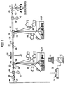
- FIG. 1 is a general block diagram of a cable television system.
- Cable television system as used herein refers to all systems involving the transmission of television signals over a transmission medium (fiber optic cable or coaxial cable) to remote locations.
- a cable television system may comprise a community antenna television distribution system, a satellite signal distribution system, a broadcast television system, a private cable distribution network, either industrial or educational, or other forms of such systems.
- Each remote location of a television receiver may comprise the location of a particular subscriber to a subscription television service, plural subscribers, single subscribers having plural television receivers or private locations in a private cable distribution network. Consequently, the term subscriber as used herein refers to either a private subscriber or a commercial user of the cable television system.
- Headend 10 is a connecting point to a serving cable or trunk 28 for distributing television channels over feeder lines to drops 66, 88 and finally to subscriber locations.
- E.I.A. Electronic Industries Association
- N.T.S.C. National Television Subcommittee
- the principles of the present invention apply equally to other standard and non-standard baseband standard definition and proposed high definition television signal formats.
- the principles of the present invention are not limited to television services furnished from a headend but may include utility meter reading, burglar alarm reporting, digital or other stereophonic audio delivery systems, video or telephonic services and the like.
- Headend 10 typically comprises a source of television programming (not shown).
- the television program source may be a satellite television receiver output, a program produced by a television studio, program material received over a microwave or broadcast television link, a cable television link output. or any other source of television programming consistent with the present invention.
- the program source material need not be limited to conventional television but may comprise teletext, videotext, program audio, utility data, or other forms of communication to be delivered to a remote location over the serving cable or trunk line 28 and subsequently over feeder lines and, then, drop lines 66, 88. Addressing to provide different levels of service is obtained with a computer system including a system manager computer 16 and a billing computer 18.
- trunk line 28, feeder lines, and drop lines 66, 88 are constructed of coaxial cable.
- any one of these lines could be a fiber optic cable. Due to the cost of the installation and the need for a high quality initial transmission from headend 10, trunk line 28 is typically the only line constructed of fiber optic cable.
- Program material provided by the source may be premium or otherwise restricted or desirably secured from receipt at unauthorized receiver locations. It may be provided over any channel of the 50-550 MHz (or larger band) cable television spectrum. "Premium channel” or “premium programming” as used herein refers to a channel or program which is secured from unauthorized receipt either because of its premium or restricted status.
- Off-premises apparatus 24 of housing 60 may be coupled to subscribers having on-premises converter/decoders or decoders and off-premises apparatus housing 58 may be utilized for coupling to new subscribers to the system.
- Off-premises apparatus 20, 22, 24, and 26 also form part of a reverse data transmission path as will be discussed in greater detail below.
- Off premises apparatus 20, 22, 24, and 26 respectively comprise housings or enclosures 56, 58, 60, and 62 and covers 48, 50, 52, and 54.
- headend 10 may provide scrambled television programming as well as premium programming in the clear and a scrambler may be provided as long as converters/decoders remain in the system for unscrambling scrambled program transmission.
- off premises apparatus 24 may be coupled to subscribers still having on-premises converters/decoders and off premises unit 22 may be utilized to couple new subscribers to the system.
- converter/decoders at subscriber locations may later be entirely replaced by interdiction apparatus of the present invention.
- Descrambling or decoding equipment may also be provided at an off-premises housing.
- Headend 10 includes an addressable data transmitter 14 for transmitting global commands and data downstream to all subscribers or addressed communications for reception by a particular subscriber. Such forward data transmission may be conducted over a separate data carrier from the cable television spectrum, for example. at 108.2 megahertz. Forward data transmission may also be over an unused default channel from the television spectrum.
- Global commands generally take the form of operation code and data while addressed communications further include the unique address of a particular subscriber.
- forward data communications may take the form of in-band signals sent with a television channel superimposed, for example, upon an audio carrier during a special time period, for example, a period corresponding to the vertical blanking interval of the associated video signal.
- in-band signaling may be required for the operation of certain converter/decoders known in the art.
- commands to authorize service to a particular subscriber may be transmitted in-band or on a separate data carrier and typically involve transmitting a unique address of a particular subscriber unit, a command, and data.
- Decoders in the system receive the command, decode it, determine if the command is to be acted on, and if so perform the desired action such as provide a subscriber with pay-per-view credits or generally authorize services. Consequently, headend 10, cable television serving cable or trunk line 28, and converter/decoders and television receivers (TV's or VCR's) at a typical subscriber premises comprise a typical known cable television system.
- Channel program or authorization data is transmitted via an addressable data transmitter 14 over a trunk line 28 to feeder lines with interspersed signal amplifiers 34 and power supply equipment 41, 42, 44, 46 provided as required.
- the serving signal is dropped via drops 66, 88 to a subscriber location at a pole 36 or from a pedestal at underground cable locations.
- Off premises unit 24 may be connected via connector 86 and drop 88 to a conventional converters/decoders which serve several functions. Responsive to an addressed communication from headend transmitter 14, channel or program authorization data is updated in an authorization memory if the address associated with the addressed communication matches a unique address of the subscriber decoder. For example. the subscriber address may comprise a plurality of bits over and above the actual number of subscribers in a system, the additional bits insuring the security of the address. The premium channel or program is then stored in the authorization memory of the converter/decoder. Television programming is normally converted to an otherwise unused channel such as channel 3 or 4 of the television spectrum by a converter portion of converter/decoder. Its premium status is checked against the data stored in authorization memory. If the programming is authorized, the decoder portion of the converter/decoder is enabled to decode authorized scrambled premium programming.
- the provided television receiver may be a conventional television receiver or may be a so-called cable ready television receiver. Because of the advent of cable ready television receivers, there is no longer a requirement at a subscriber premises for the converter portion of a converter/decoder because a converter is built into such television receivers.
- units 20, 22, 24, and 26 are mounted on a strand 38 supporting the cable to a pole 36, or provided via a pedestal, as is shown more particularly in U.S. Patent No. 4,963,966.
- the units may also be mounted indoors in an equipment closet of a multiple dwelling unit or to the side of a subscriber's premises. Inside the units is common control circuitry for tapping into the broadband television and data transmission spectrum.
- a strand-mounted apparatus 56 serving four drops 66 to subscribers via connector 64. In practice, four or more subscribers and up to four or more drops 66 may be served by interdiction apparatus 20.
- plug-in subscriber modules may be provided for an off-premises housing.
- additional services requiring two way data transmission such as subscriber polling, home shopping, burglar alarm, energy management and pay-per-view services may be provided via four or more service modules comprising reverse path signal combining circuitry of apparatus 56.
- a subscriber transaction terminal apparatus in a subscriber's premises simply comprises a subscriber-controlled data transmitter for transmitting data on the subscriber drop 66 in only one direction. namely, to interdiction apparatus 20.
- the subscriber premises will be assumed to include at least one cable ready conventional television receiver, TV or VCR. Consequently, subscriber equipment need not comprise a tunable converter for converting a received cable television channel to an unused channel such as channel 3 or 4.
- the subscriber transaction terminal device comprises data entry or sensing means. data confirmation means. i.e., a display or alarm, if required, and a data transmitter coupled between the drop cable and the cable ready television receiver.
- Power for off-premises apparatus 20 may be provided over the cable from the headend direction via power supplies 41,42 or be provided via the subscriber drop 66 or by a combination of such means.
- power may be even provided by rechargeable means such as solar cells or other external or replaceable internal sources such as batteries.
- the subscriber transaction terminal equipment according to the invention described by the present application is preferably battery powered.
- All off-premises service providing apparatus 20, 22, 24, and 26 may be secured in a tamper-resistant housing or otherwise secured as described by U.S. 4,963.966 or secured in a locked equipment closet of an apartment complex. If located in a place exposed to the elements, the housing should be water-tight. Also, the housing should be designed to preclude radio frequency leakage.
- Interdiction apparatus 20 is uniquely addressable by headend 10 just as is a known converter/decoder. If two bits of a plural bit unique subscriber address are associated with uniquely identifying one plug-in slot for one of four subscriber modules. Common control circuitry may be uniquely addressed with remaining address data not used to secure the data communication. Just as premium programming is transmitted in the clear and since no data communication is necessarily required with a subscriber premises. a subscriber address need not be transmitted in a secure form. Nevertheless. address security may be desirable so long as converter/decoders or other unique address requisite equipment is provided at a premises.
- Interdiction apparatus 20 comprises addressable common control circuitry, a plug-in service module and up to four (or more) plug-in subscriber modules. Upon receipt of subscriber specific premium program, subscriber credit or channel authorization data, the data are stored at memory of common control circuitry of off-premises interdiction apparatus 20.
- Interdiction apparatus 20 further comprises a diplexer for providing a forward transmission path which is coupled to automatic gain control circuitry of the common control circuitry.
- the common control circuitry forwards jamming frequency control data to a subscriber module.
- Channel interdiction circuitry associated with each subscriber module then selectively jams unauthorized premium programming dropped via a particular drop 66 to a particular subscriber. Consequently, interdiction apparatus 20 is reasonably compatible with downstream addressable authorization data transmission known in the art. No scrambling of premium channels (and no resulting artifacts) is necessary or desirable. Furthermore, no additional forms of service security are necessary such as channel encryption. in-band channel or tier verification or other security measures.
- the would-be service pirate must attempt to remove a particular pseudo-randomly timed jamming signal placed at a varying frequency or seek to tamper with the off-premises interdiction apparatus 20 or derive a signal from shielded and bonded cables which should likewise be maintained secure from radio frequency leakage.
- other tamper protection may be provided for apparatus 20.
- Two way data transmission is provided via a so-called sub-split frequency spectrum comprising the band 5-30 megahertz for upstream. reverse path transmission toward headend 10 and a spectrum from 54-550 megahertz for downstream forward transmission.
- an amplitude shift keyed data transmission signal at approximately 5 MHz is used for communication on drop 66.
- a binary phase shift keyed signal is used for upstream data transmission in the T8 band to headend 10.
- Distribution amplifiers 34 distributed along the distribution plant according to known prior art design techniques separate and separately amplify the two transmission bands. They are distributed along the transmission path in a manner so as to preclude the carrier-to-noise ratio of either transmission path from being too low. Even with such design techniques, the return path is highly susceptible to interference at any point.
- a radio frequency data receiver and data processor for receiving data transmissions from the off- or on-premises subscriber equipment.
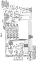
- feeder cable 28 is shown entering off-premises interdiction apparatus 20 at FEEDER IN and leaving at FEEDER OUT.
- Power PWR may be provided via the feeder cable, by means of the subscriber drop or locally by internal or external means.
- input power may be of alternating or direct current.
- a directional coupler 210 which may be in the form of a plug-in module taps into the broadband serving cable 28.
- a broadband of radio frequency signals is thus output to highpass filter 220 of diplex filter 295.
- Highpass filter 220 passes a downstream band of frequencies, for example, 54-550 megahertz comprising at least the cable television spectrum and any separate data carrier frequency, such as 108.2 MHz. and blocks the upstream band of frequencies, for example, 5-30 megahertz (in a bi-directional application).
- the cable television spectrum may particularly comprise a narrower frequency band from about 54 MHz to 350 MHz.
- Lowpass or bandpass filter 221 passes at least the 0-30 MHz spectrum and more particularly a pass band comprising the T8 band from approximately 14-18 MHz. As will be more particularly described herein, one of twenty-three data channels may be selected for upstream data transmission from within the T8 band to avoid noisy regions of the spectrum.
- Circuitry associated with broadband signal "seizure" from the distribution cable 28 may be conveniently mounted on a single board, conveniently named a seizure board of interdiction apparatus 20. More particularly described in Figure 15 of U.S. Patent No. 4,963,966, but described in general terms herein as at least comprising the directional coupler 210 and diplex filter 295 of Figure 2.
- a common automatic gain control circuit as disclosed in Figure 2 comprises variable attenuator 230, RF amplifier 233, directional coupler 232, and AGC control circuit 231. This automatic gain control circuit appropriately regulates the broadband RF signal power to fall within established limits.
- the common circuitry of Figure 2 is collocated or closely located to the subscriber modules which will be further described in connection with Figure 3 and may be contained in the same housing with the service units for each subscriber which will be described in connection with Figure 7.
- a data receiver 240 for receiving downstream forward data transmissions from the addressable data transmitter 14 located at headend 10.
- Data receiver 240 receives data transmitted, for example, over a data carrier of 108.2 megahertz and provides unprocessed data to data decoder 250.
- data decoder 250 processes the data and provides the separately transmitted data to microprocessor 260 for further interpretation in accordance with a built-in algorithm.
- Microprocessor 260 is most efficiently chosen to alleviate as many responsibilities from any microprocessor provided for an individual subscriber module and so is most conveniently an eight bit microprocessor having eight kilobytes of internal code such as a Motorola 68HC05C8.
- Received data may be stored in uninterruptable memory 270 by microprocessor 260.
- Data may be stored in memory 270 and jamming frequency control data downloaded when needed to a subscriber module according to Figure 3 via a serial peripheral interface bus 290 connecting microprocessor 260 with separate microprocessors 300 associated with each provided subscriber module as shown in Figure 3.
- microprocessor 260 communicates, for example. upstream frequency and amplitude control data to microprocessors associated with each service module as shown in Figure 7 over interface 620 which may comprise the same bus system as serial bus 290.
- a parallel bus with bus contention among the several modules and processor 260 may be substituted as appropriate for buses 290 and 620.
- Variable attenuator 230 regulates the received broadband of picture carriers to a reference level while the microprocessor 260 controls the jamming carrier level outputs of associated subscriber units within the prescribed range.
- Microprocessor 260 consequently interprets both global communications addressed to common control circuitry or communications addressed to unique subscribers for operation of subscriber modules such as service credit or authorization commands or both. If appropriate, microprocessor 260 ignores global or addressed communications to other interdiction apparatus or to conventional converter/decoders.
- An example of global communications peculiar to interdiction apparatus 20 is premium channel frequency data for each premium channel or channel over which premium programming at a particular point in time is provided via headend 10.
- Examples of addressed communications to common control circuitry include communications comprising premium channel or programming authorization information or communications instructing the common control circuitry to provide credit to a particular subscriber.
- Examples of commands for operation of service modules in accordance with Figure 6 may comprise commands to set transmit level and channel for upstream transmissions in the T8 band.
- the radio frequency upstream transmissions from on-premises equipment are combined at a multiplexer of reverse path signal combining circuitry according to Figure 4 for subsequent upstream transmission.
- a separate data transmitter is provided in the reverse path signal combining apparatus according to Figure 4 for upstream transmissions to the headend.
- Serial peripheral interface buses 290, 620 may be a two way communications link by way of which microprocessors 300 ( Figure 3) or microprocessors 600 (Fig. 7) associated with subscriber and service modules respectively, may, at least. provide status reports to microprocessor 260 upon inquiry.
- a microprocessor of either Figures 3 or 7 may tap into a parallel contention-type bus 290 and bid for communication to either a microprocessor 260 of common equipment or another microprocessor 300, 600 or may directly communicate with any of the other associated microprocessors over a separate serial bus 290, 620.
- Radio frequency splitter 280 provides broadband radio frequency signals comprising a broadband cable television service spectrum separately to each subscriber module according to Figure 3 that is provided.
- a reverse path is required to headend 10 or common circuitry according to Figure 2 for special additional services. Consequently, a signal combiner 400 of a reverse path data transmission module according to Figures 4 and 7 is provided for receiving data communications from each of the four subscriber modules in an opposite manner to splitter 280. Certain data may be transmitted back toward the headend via an RF return path according to either Figure 4 or 7 and a forward transmission path toward the subscriber may be provided in a conventional manner according to Figures 2 and 3.
- FIG 3 is an overall block schematic diagram of a subscriber module of interdiction apparatus 20 including a diplex filter 395.
- a microprocessor 300 is associated with a particular subscriber module and communicates with microprocessor 260 of Figure 2 over a serial peripheral interface bus.
- Microprocessor 300 may comprise an eight bit microprocessor equipped with only two kilobytes of code, this microprocessor being relieved of overall control responsibilities by microprocessor 260. Consequently, microprocessor 300 may conveniently comprise a Motorola 68HC05C3 microprocessor or similar unit.
- a reverse path may be provided via a lowpass filter 392 of diplex filter 395 to a service module (according to Figures 4 or 7) collocated with common control circuitry as described in Figure 2 and subscriber modules according to Figure 3.
- a 5-30 megahertz or other lowpass band more particularly, a 0-15 MHz lowpass band, may be provided for upstream, reverse transmissions from corresponding subscriber equipment on the subscriber premises.
- Such a reverse path is completed to the subscriber via terminal OS.
- power may be transmitted up the subscriber drop to the subscriber module of Figure 3 and withdrawn at terminal OS.
- the broadband radio frequency television spectrum signal from Figure 2 is provided to terminal IS.
- terminal IS Referring to the path connecting terminal IS to terminal OS, there are connected in series a service denying switch 389, a radio frequency amplifier 387, a jamming signal combiner 385, and a high pass filter 391.
- Service denying switch 389 is under control of microprocessor 300.
- service denying switch 389 may be opened.
- a high frequency amplifier 387 may be powered down under control of microprocessor 387 whenever service is to be denied. Otherwise, amplifier 387 may be set at discrete gain levels, under microprocessor control, to provide supplemental gain to the broadband television signal if a subscriber has a plurality of television receivers (TV's and VCR's) over and above a nominal amount.
- An appropriate control signal waveform output SDPS is provided by microprocessor 300 for controlling switch 389. Also the same ON/OFF control signal that is used to control the switch 389 may control the powering up and down of amplifier 387 as control signal SDHP.
- jamming signals are interdicted at directional combiner 385 under microprocessor control. Because of the directional characteristic of radio frequency amplifier 387, jamming signals cannot inadvertently reach the common control circuitry of Figure 2 or the serving cable.
- Highpass filter 391 of diplex filter 395 prevents any return path signals from reaching combiner 385 and passes the broadband spectrum including any jamming signals toward terminal OS.
- Reverse path signals for example, in this embodiment may be radio frequency signals below 30 megahertz.
- the broadband television spectrum is presumed to be in the 50-550 megahertz range. However, interdiction of premium channel viewing may be allocated anywhere desired within a broader or discontinuous cable television spectrum to be jammed. Consequently, filters 391 and 392 are designed in accordance with this or similarly selected design criteria to block or pass broadband television or reverse path signals as required.
- Microprocessor 300 responsive to common microprocessor 260, controls the frequency and power level outputs of four (or five if necessary) voltage controlled oscillators 341-344, each of which oscillators jams premium channel frequencies within an allocated continuous range of frequencies.
- the frequency of the oscillators is set over leads FREQ1-4 in a manner described in U.S. Patent 4,912,760.
- a power level and ON/OFF operation of the oscillators 341-344 are controlled over leads OPWR1-4.
- the sum of all such allocated portions comprises the entire television spectrum to be jammed (even where non-premium channels are normally transmitted). Also. in accordance with the depicted interdiction system, the television spectrum to be jammed may comprise discontinuous portions or intentionally overlapping portions.
- FIG. 4 is a block diagram of off-premises interdiction apparatus 20 of Figure 1.
- One of four subscriber modules is shown and the details of the circuitry for jamming programming are omitted.
- Drop cable 66 from subscriber No. 1 is shown connected to high pass filter 391.
- lowpass filter 392 having a cut-off frequency of 15 MHz for passing an amplitude shift keyed data signal centered at 5 MHz to an associated service module 400.
- Lowpass filter 392 and highpass filter 391 together comprise diplexer 395 of Figure 3.
- Service module 400 shown only in simplified form. comprises a multiplexer 401 for combining signal path inputs from each one of four subscriber modules.
- a receiver 402 receives the data transmissions from the subscribers, and a transmitter 403 is provided for upstream transmission, preferably in the T8 band.
- the seizure board of interdiction apparatus 20 is shown also in simplified form.
- Directional coupler 210 is shown connected for passing a high passband via highpass filter 220 toward the subscriber while lowpass filter 221 receives the output of the data transmitter 403 of service module 400 for transmission toward the headend.
- Lowpass filter 221 and highpass filter 220 together comprise diplexer 295 of Figure 2.
- diplex filter 295 is provided between directional coupler 210 and the common circuitry.
- diplex filter 395 combines the forward and reverse path output and input respectively. A combined signal then is provided toward the subscribers.
- diplex filter 295 and diplex filter 395 provide communication paths toward the headend 100 and subscriber respectively.
- a plug-in slot of off-premises equipment 20 and coupled to each diplexer is a service module according to Figures 4 and 6.
- FIG. 5 is a block diagram of a transaction terminal 500 in accordance with the present invention.
- the interdiction RF-IPPV transaction terminal is an interface between the subscriber and the interdiction system.
- Terminal 500 inter alia , allows the subscriber to make impulse pay-per-view purchases.
- Terminal 500 includes a key-pad 520 having four pushbuttons 535-538 respectively labelled “ChanUp”, “ChanDn", “Buy”, and “Cancel” and a two-digit LED display 510.
- Channel display 510 can scroll through channel or event numbers until the desired event or channel is displayed.
- Transaction terminal 500 includes a microprocessor 501 such as a Zilog Z86C06 which reads the four pushbuttons 535-538. controls the two-digit LED display 510, and controls the transmission of purchase information to the interdiction unit located outside the home. When no transactions are in progress. microprocessor 501 is preferably in a low-power state and power to the rest of transaction terminal 500 is switched OFF. When any of the four buttons are pressed, microprocessor 501 is activated and power is switched ON to the rest of the terminal circuitry. When the terminal is active. microprocessor 501 controls the user and communication interfaces as described below.
- a microprocessor 501 such as a Zilog Z86C06 which reads the four pushbuttons 535-538. controls the two-digit LED display 510, and controls the transmission of purchase information to the interdiction unit located outside the home. When no transactions are in progress. microprocessor 501 is preferably in a low-power state and power to the rest of transaction terminal 500 is switched OFF. When any of the four buttons are
- Terminal 500 permits a subscriber to purchase IPPV events and to also cancel purchases within a predetermined time after buying.
- the interdiction unit not the terminal 500, determines whether a cancel is permitted. When a channel is selected, the terminal makes no indication that an event is available or has been previously purchased. If no keys are pressed for twenty seconds, the terminal enters an idle state.
- Pressing the "ChanDn” and “ChanUp” buttons results in the respective decrementing and incrementing of the channel display of display 510.
- Channels "0" through “9” are displayed as single digits.
- the two display digits are preferably strobed on and off so that when one digit is ON the other is OFF.
- the strobe rate is preferably about 100 Hz, although the invention is in no way limited in this respect. Pressing “ChanDn” when the display reads “0” results in the channel number "99” being displayed. Pressing “ChanUp” when the display reads "99” results in the channel number "0” being displayed.
- display 510 increments/decrements through the next three channels at a rate of 2 channels per second and then continues incrementing/decrementing the display at a rate of 4 channels per second.
- the terminal Prior to the purchase of an IPPV event. the terminal is in an idle or sleep state and the display is blank. When the subscriber presses any key, microprocessor 501 controls display 510 to display "37". Preferably, terminal 500 does not display the most recent channel purchased. The subscriber then uses the "ChanUp” or “ChanDn” keys on keypad 520 to select the channel of the event to be purchased. After the channel has been selected. the subscriber presses the "BUY” button on keypad 520. Display 510 then alternately displays “bY” and the selected channel number. The subscriber then presses the "BUY” button on keypad 520 a second time. Display 510 displays the channel number and the purchase information is transmitted via transmitter 540 over a carrier synthesized by ceramic resonator oscillator 530 to the interdiction unit outside the home.
- terminal 500 is in the idle or sleep state and display 510 is blank.
- microprocessor 501 controls display 510 to display "37".
- Display 510 does not display the most recent channel purchased.
- the subscriber uses the "ChanUp” and “ChanDn” keys on keypad 520 to select the channel of the event to be cancelled.
- the subscriber presses the "CANCEL” button on keypad 520.
- Display 510 then alternately flashes "CA” and the selected channel number.
- the subscriber then presses the "CANCEL” button on keypad 520 a second time.
- Display 510 displays the channel number and the cancel information is transmitted via transmitter 540 to the interdiction unit outside the unit.
- Purchase windows are preset time intervals prior to or at the beginning of a pay per view event program in which a subscriber may purchase an event.
- Cancel windows are set as an interval of time after an event is purchased during which the purchase of the event may be canceled.
- Purchase and cancels windows may be set remotely by a transaction from headend 10 to the interdiction apparatus 20.
- the buy or cancel message is transmitted by transmitter 540 periodically and at random times as further described below. After the transmitter 540 has completed its periodic and random transmissions. for example. occurring over a period of about twenty seconds, the microprocessor 501 may turn itself and its peripheral equipment OFF to conserve power. Furthermore, no record need be maintained in microprocessor 501 memory. For example. the decision to cancel a buy signal will be made at interdiction apparatus 20. and not at the transaction terminal.
- both messages preferably contain an operation code, a channel number, and a checkbyte.
- Data transmission is ASK (Amplitude-Shift-Keyed) at 9600 baud with at least 0.1 milliseconds between bytes.
- the buy and cancel messages are three bytes long and each contain an operation code, the selected channel number, and a checkbyte. Each byte takes 1.0 millisecond and the time between bytes is allowed to be anywhere from 0.1 to 0.5 milliseconds, so the message length can be anywhere from 3.2 to 4.0 milliseconds long.
- transaction terminal 500 repeats the message until 450 milliseconds have passed. This is a first burst of messages. After each message, there is a random waiting period of between 15 and 30 milliseconds. The random waiting period is determined by a random number generating routine of microprocessor 501. The routine is seeded with an eight bit random number seed so that the probability of two transmitters choosing the same series of random numbers is 1 in 256 (2 8 ). After the first burst of messages, there are two more bursts within the next 5.0 seconds, each burst again lasting 450 milliseconds. The time between bursts is also random and based on an 8 bit seed.
- Transaction terminal 500 is coupled to a diplex filter 595 between the on-premises television receiver and the interdiction apparatus at drop 66.
- the receiver of the service module 400 and transmitter 540 of Figure 2 need not comprise a transceiver means coupled to drop 66 but may comprise a radio frequency broadcast transmitter employing over-the-air transmission. Diplex filters 395 and 595 would then not be required. Ultrasonic, infrared or low power remote control radio frequency signal broadcast and reception apparatus could be substituted.
- the terminal may be self-powered or utilize a very low degree of power.
- the apparatus shown in Figure 5 may be simply powered by three batteries 550 which may be replaced every year or so.
- Switch 560 may be associated with a key or combination lock. For example, a combination of the four keys of keyboard 520 may unlock switch 560.
- microprocessor 501 may read data from keypad 520 and sensor devices 520'.
- the data entry comprises four or more bits of data digitally identifying sixteen portals or windows which may have been breached, while display 510 may be an alarm device.
- the sensor inputs may identify the type of meter, electric, gas, or water, and the data may be the reading itself.
- Other transaction terminals or a common terminal may be provided for these and other services such as home shopping, voting, etc.
- the transaction terminal of Figure 5 further comprises a transmitter 540 for, for example, providing an amplitude shift keyed output data signal, for example, at 9600 baud and comprising operation code and data, i.e. buy channel 88, alarm at portal 12, electric meter at 373 kilowatts.
- the output data signal is passed through bandpass filter 592 centered at 4.92 MHz toward interdiction apparatus 20. The output data signal is precluded from interfering with television reception by 54 MHz high pass filter 591.
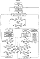
- Figure 6 is a flow diagram illustrating a method in which a subscriber may purchase a pay per view event.
- the method may be implemented in software stored in the microprocessor 501 of the transaction terminal 500.
- the software controls the operation of microprocessor 501.
- microprocessor 501 is in an idle or sleep state in which it is shut down to conserve power and display 510 is switched OFF (A-10).
- the microprocessor is awakened by the actuation or pressing of any key (A-12) and control passes to the main loop of the program.
- a steady channel number is displayed on display 510, for example channel 37, to provide a starting point for the subscriber.
- Channel 37 was chosen because it is a convenient mid-point among the presently available premium channels and reduces the number of times the "ChanUp" and/or "ChanDn" keys are pressed to reach a desired premium channel. It will be evident that any steady indication that the terminal is active can be provided on the display.
- a twenty second software timer is also started to initiate an active cycle. The timer may alternatively be a counter or other timing mechanism utilized in the art.
- the timer is tested to determine whether the twenty seconds has elapsed. If twenty seconds has elapsed from the initiation of the active cycle before the pressing of another key (A-18), it is assumed the subscriber has changed his mind and does not want to purchase a premium event. In such a case, the program transfers control back to block A-10 where microprocessor 501 and display 510 again enter the sleep mode.
- the program causes microprocessor 501 to control display 510 to alternately flash the selected channel number and the two letters "bY" (A-26).
- the twenty-second timer is restarted at block A-26.
- the program checks the twenty second timer in block A-32 to determine whether a time out has occurred. At this time, the subscriber may still change his mind about purchasing the premium event. If no further key is pressed by the subscriber (A-34). the twenty-second timer will time out and control is transferred to block A-10 where the microprocessor and display enter the sleep mode.
- the program respectively determines whether a "BUY” key or a "CANCEL” key has been pressed in blocks A-36 and A-38. If the "BUY” key has been pressed, then microprocessor 501 causes transmission of the purchase data for that particular event to the interdiction unit 20 (A-40). After the transmission of the buy message, control is transferred to block A-14. If, however, after selecting an event to buy, the "CANCEL” key is pressed (A-38), control is immediately transferred to block A-14 and no buy message is transmitted. In this manner, a simple transaction operation can be executed to buy a premium event and transfer associated billing information to the interdiction unit or to cancel the buy command prior to transmission.
- the loop entered at block A-22 describes an operation whereby a buy which has been transmitted may be cancelled.
- the display alternately flashes the selected channel (A-28) and the letters "CA" to alert the subscriber that the cancel message is ready to be transmitted.
- the twenty-second timer is restarted and the program determines whether a key is pressed (A-44) prior to the timing out of the timer (A-42). If there is no confirmation of the cancel message by pressing of the "CANCEL" key (A-46), the program times out and control returns to block A-10 and the microprocessor and display to go into the sleep mode. However, if the initial cancel command is confirmed in block A-46 then the microprocessor controls the transmitter to transmit the cancel message (block A-48). After the microprocessor has transmitted the cancel message to the interdiction unit, the program returns to block A-14.
- a premium program may be purchased during a purchase window fixed by headend 10.
- a subscriber may purchase an event in a purchase window beginning thirty minutes before the scheduled start of the program and ending ten minutes after the program start.
- a cancel window during which a subscriber may cancel a purchase may likewise be configured by headend 10.
- FIG. 7 there is shown a block schematic diagram of a service module such as an IPPV module of interdiction apparatus 20 which provides an RF data return path.
- the service module of Figure 7 comprises a signal multiplexer 630, a data receiver 402 (see Figure 4) including elements 635, 645, 650, 655.
- a microprocessor 600 which may comprise on-board RAM and a data interface 620 with motherboard processor 260.
- a transmitter 403 (see Figure 4) including a BPSK modulator 680 for upstream data transmission.
- the service module of Figure 7 is shown coupled between subscriber module equipment according to Figure 3 including diplexer 395 and diplex filter 295 at the front end of common circuitry according to Figure 2.
- All return data communications for all services are assumed to be provided via the service module of Figure 7.
- Home shopping, subscriber polling, burglar alarm, pay per view and all other services are provided via the depicted circuitry and any associated data are relayed to headend 10 via transmitter 403.
- a meter reading signal from a power company is received via the data receiver 240 of Figure 2 from headend 10, interpreted by microprocessor 260 and relayed to microprocessor 600.
- Microprocessor 600 in turn actuates a data transmission to, for example, relay stored data in one of three non-volatile memories 610-612 to headend 10 which had been previously transmitted by the subscriber terminal of Figure 5 on a periodic basis.
- a burglar alarm which may be activated on the subscriber premises.
- the alarm may be formatted and modulated for transmission at the subscriber's premises up the drop to the data receiver.
- the message then is interpreted as such by the microprocessor 600 which then controls the transmitter 403 to transmit an appropriate alarm message to the headend.
- a subscriber via the terminal of Figure 5 may control common circuitry or subscriber circuitry as appropriate, for example, an RF power amplifier 387 of a subscriber module according to Figure 3.
- the common circuitry is signaled via interface 620 of the buy command.
- the processor 260 determines the authorization status of the subscriber and then authorizes the channel for the time of the event.
- the jamming oscillator for the associated channel is controlled so as to not jam that channel at the time of the paid for event.
- Headend 10 periodically transmits a channel. event and time of event data memory map to update random access memory associated with processor 260 over an out-of-band 108.2 MHz carrier signal as described above for transmitting addressed and global communications.
- additional non-volatile memory is not required in an out-of-band system for storing event/channel/time tables, such as is an interdiction cable television system.
- a channel, event and time table map must be stored in non-volatile memory 270 associated with processor 260 because of the relative infrequency and limited capacity of an in-band communications link compared with an out-of-band link from a headend 10 to remote CATV apparatus.
- RF data transmitter 403 may transmit data in accordance with well known techniques on any data carrier in the subsplit band. for example, between 5 and 30 megahertz.
- PSK or FSK data transmissions have been notoriously susceptible to noise interference which has been practically impossible to avoid over time. Once a clear channel is uncovered, the next day, interference from, for example, a previously undetected ham radio operator precludes its use.
- the return data may be spread over a large portion of the spectrum and so travel secure and hidden in the noise.
- a further alternative to spread spectrum, and one which alleviates its high cost, is to provide a plurality of data transmissions over a plurality of data channels spread over the entire return path spectrum comprising, for example, the T8 band.
- BPSK modulator 680 may be frequency controlled to alternately provide a number of separate data transmissions over any selected one of a plurality of separate data channels.
- frequency synthesizer circuit 665 for example, an MC145157-2 is provided to control a phase lock loop comprising additionally low pass filter 670 and voltage controlled oscillator 675 to output a particular transmit carrier frequency in the 15.5 to 17.7 MHz T8 band.
- Each data transmission is complete unto itself. Statistically, at least one such transmission on one channel is assured of reaching the headend 10 on any given day.
- bandpass filter 635 Connected between multiplexer 401 and microprocessor 600 are a bandpass filter 635 centered at approximately 5 MHz which may be identical to the bandpass filter 592 of Figure 5.
- the data to be passed typically falls within the range of 4.920000 MHz plus or minus 75 KHz with an accuracy of about two per cent.
- Amplifier 645 amplifies the received signal from the transaction terminal of Figure 5 just before detection at, for example, diode detector 650.
- the detected signal is compared at comparator amplifier 655 with a voltage reference provided by reference source 652.
- the output of comparator 655 is a serial data stream which is input to microprocessor 600.
- microprocessor 600 The received data is interpreted at microprocessor 600 and forwarded via interface 620 to common circuit microprocessor 260 as appropriate. For example, microprocessor 260 is notified of any buy or cancel transaction initiated at a transaction terminal according to Figure 5.
- BPSK modulator 680 Data to be transmitted to the headend, for example. billing data responsive to a polling request, is forwarded over a line to BPSK modulator 680.
- the frequency or gain of the BPSK data signal may be controlled from the headend to avoid noisy channels and to assure sufficient signal strength through the system.
- Frequency control is output to the divide by N and divide by R frequency dividers of frequency synthesis circuit 665.
- Gain control in a step-wise manner is provided via a level control lead to the BPSK modulator 680.
- anti-babble circuit 690 is provided sensitive to microprocessor 600 and in accordance with U.S. Patent No. 4,692,919.
- the interdiction apparatus is advised of upcoming events by number, time and channel from the headend 10 via the addressable in-band or out-of-band system described above.
- the service module in turn. is told of the events by the motherboard microprocessor 260 over the motherboard interface 620, preferably a serial peripheral bus link interface.
- the service module receives buy and cancel information from the transactions terminal of Figure 5 in four subscribers' homes, which, in turn, may comprise up to four transaction terminals associated with four television receivers.
- the multiplexing circuitry 401 is controlled by microprocessor 600 to allow receipt of data from only one subscriber at a time.
- the microprocessor 600 may scan the subscriber inputs in rapid fashion until data is sensed at one port. The switch then remains stationary at that position until the cessation of receipt of data.
- One multiplexer circuit which may be used comprises a 74 HCW052 integrated circuit.
- the service module determines if the buy or cancel is valid, and then causes the data, if valid, to be stored in non-volatile memories 610, 611, 612. Up to a certain number, for example, sixteen, thirty-two, or sixty-four, event purchases, including channel, event ID number, and time of purchase are stored in subscriber tables tabulated by subscriber identification or address. Each subscribers table size may be controlled by the headend up to the maximum size. for example, thirty-two events.
- the service module communicates the information to the motherboard via the motherboard interface 620.
- the motherboard microprocessor 260 uses the information to signal the appropriate subscriber module microprocessor 300 to unjam the channel at the predetermined time of the event.
- RF data transmitter 680 responsive to microprocessor 600. forwards billing data to the headend 10.
- Messages from the transaction terminal need only comprise an operation code of predetermined length and a channel number.
- a check byte i.e. parity, checksum, or error correcting codes may be used as appropriate.
- the microprocessor 600 identifies the source of the transmission via the position of multiplexer 401.
- microprocessor 260 may control or initiate all communications.
- the communications comprise the following: a status check. an address information message to advise of subscriber addresses. an authorization request to obtain channel authorization information. an authorization poll to obtain the present channel status, a message for controlling headend communication, and an NVM or RAM memory poll or request.
- a status check In each such communication from the motherboard to the service module, there is included at least an operation code. In others, there is included a channel number, an address, and/or data, as appropriate.
- Reply communications from the module to the motherboard microprocessor typically comprise responsive data or signals to the motherboard to request certain data.
- a simple on-premises device which provides a subscriber in a CATV interdiction system with IPPV capability.
- the subscriber terminal includes only a transmitter and thus does not receive commands or data from the interdiction apparatus. Data is entered into the subscriber terminal via a simple keyboard and the terminal is controlled by a small, inexpensive microprocessor. Accordingly, the benefits of impulse pay-per-view may be obtained in a CATV interdiction system without seriously compromising the cost benefits associated with the concept of removing apparatus from a subscriber's premises. Further, the problems associated with having multiple subscriber units coupled to the same drop are overcome by repeating buy and cancel messages at plural, random times.
- the subscriber terminal may be addressed by a remote control such as an infrared remote.
- a remote control such as an infrared remote.
- an LED or other type of display may be utilized to display time of day, credit limits, authorization codes, and the like. Accordingly, the foregoing description should be taken as illustrative and not in a limiting sense.
Landscapes
- Engineering & Computer Science (AREA)
- Signal Processing (AREA)
- Multimedia (AREA)
- Two-Way Televisions, Distribution Of Moving Picture Or The Like (AREA)
- External Artificial Organs (AREA)
- Paper (AREA)
- Apparatus For Radiation Diagnosis (AREA)
- Electric Cable Installation (AREA)
- Developing Agents For Electrophotography (AREA)
- Detergent Compositions (AREA)
- Transition And Organic Metals Composition Catalysts For Addition Polymerization (AREA)
Applications Claiming Priority (6)
| Application Number | Priority Date | Filing Date | Title |
|---|---|---|---|
| US61874590A | 1990-11-27 | 1990-11-27 | |
| US07/625,901 US5245420A (en) | 1990-11-27 | 1990-11-27 | CATV pay per view interdiction system |
| US618745 | 1990-11-27 | ||
| US625901 | 1990-11-27 | ||
| EP92902199A EP0559802B1 (de) | 1990-11-27 | 1991-11-26 | Sperrsystemverfahren und -gerät für ein pro einschalten zu bezahlendes kabelfernsehprogramm |
| PCT/US1991/008922 WO1992010038A1 (en) | 1990-11-27 | 1991-11-26 | Catv pay per view interdiction system method and apparatus |
Related Parent Applications (2)
| Application Number | Title | Priority Date | Filing Date |
|---|---|---|---|
| EP92902199A Division EP0559802B1 (de) | 1990-11-27 | 1991-11-26 | Sperrsystemverfahren und -gerät für ein pro einschalten zu bezahlendes kabelfernsehprogramm |
| EP92902199.6 Division | 1992-06-16 |
Publications (4)
| Publication Number | Publication Date |
|---|---|
| EP0917366A2 true EP0917366A2 (de) | 1999-05-19 |
| EP0917366A3 EP0917366A3 (de) | 1999-10-20 |
| EP0917366B1 EP0917366B1 (de) | 2005-07-20 |
| EP0917366B9 EP0917366B9 (de) | 2005-11-30 |
Family
ID=27088322
Family Applications (2)
| Application Number | Title | Priority Date | Filing Date |
|---|---|---|---|
| EP98122662A Expired - Lifetime EP0917366B9 (de) | 1990-11-27 | 1991-11-26 | Vorrichtung zum Sperren eines Kabelfernseh-Pay-per-View-Programmsystems |
| EP92902199A Expired - Lifetime EP0559802B1 (de) | 1990-11-27 | 1991-11-26 | Sperrsystemverfahren und -gerät für ein pro einschalten zu bezahlendes kabelfernsehprogramm |
Family Applications After (1)
| Application Number | Title | Priority Date | Filing Date |
|---|---|---|---|
| EP92902199A Expired - Lifetime EP0559802B1 (de) | 1990-11-27 | 1991-11-26 | Sperrsystemverfahren und -gerät für ein pro einschalten zu bezahlendes kabelfernsehprogramm |
Country Status (10)
| Country | Link |
|---|---|
| EP (2) | EP0917366B9 (de) |
| AT (2) | ATE300152T1 (de) |
| AU (1) | AU9143291A (de) |
| CA (1) | CA2097084C (de) |
| DE (2) | DE69131400T2 (de) |
| DK (1) | DK0559802T3 (de) |
| ES (2) | ES2246520T3 (de) |
| GR (1) | GR3031163T3 (de) |
| MX (1) | MX9102215A (de) |
| WO (1) | WO1992010038A1 (de) |
Families Citing this family (10)
| Publication number | Priority date | Publication date | Assignee | Title |
|---|---|---|---|---|
| RO111887B1 (ro) * | 1993-05-28 | 1997-02-28 | Us West Technologies Inc | Metoda si retea pentru separarea serviciilor telefonice de serviciile speciale |
| US5592540A (en) * | 1993-05-28 | 1997-01-07 | U S West Advanced Technologies, Inc. | Method and apparatus for selectively delivering telephony signals on a hybrid coaxial cable network |
| BR9405384A (pt) * | 1993-05-28 | 1999-09-08 | Us West Technologies Inc | Método e aparelho para a distribuição de serviço de telefonia seguro em uma rede hìbrida de cabo coaxial |
| US6862349B1 (en) | 1993-05-28 | 2005-03-01 | Mediaone Group, Inc. | Method and apparatus for delivering secured telephony service in a hybrid coaxial cable network |
| US5615246A (en) * | 1993-05-28 | 1997-03-25 | Us West Technologies, Inc. | Method and apparatus for spurious signal detection and disconnection in a hybrid fiber/coax network architecture |
| DE4444889C1 (de) * | 1994-12-16 | 1996-07-11 | Grundig Emv | Verfahren und Schaltungsanordnung zur Realisierung eines Rückübertragungskanals vom Empfänger zum Sender in einem Gleichwellennetz |
| US5812928A (en) * | 1995-04-12 | 1998-09-22 | Watson Technologies | Cable television control apparatus and method with channel access controller at node of network including channel filtering system |
| US5699105A (en) * | 1995-09-28 | 1997-12-16 | Lucent Technologies Inc. | Curbside circuitry for interactive communication services |
| US6201562B1 (en) | 1998-10-31 | 2001-03-13 | Kar-Wing E. Lor | Internet protocol video phone adapter for high bandwidth data access |
| US7162234B1 (en) | 2003-05-20 | 2007-01-09 | Mark J. Smith | Wireless communication device |
Family Cites Families (11)
| Publication number | Priority date | Publication date | Assignee | Title |
|---|---|---|---|---|
| US4450477A (en) * | 1982-03-31 | 1984-05-22 | Lovett Bruce E | Television information system |
| US4580161A (en) * | 1982-11-22 | 1986-04-01 | Pico Products, Inc. | Cable television subscriber control system including addressable filters having a variable pole |
| US4494138A (en) * | 1983-05-11 | 1985-01-15 | Comsonics, Inc. | Segmented upstream management for cable television |
| JPS61502299A (ja) * | 1984-05-19 | 1986-10-09 | エ−エム・ケ−ブル・ティヴィ−・インダストリ−ズ,インコ−ポレイテッド | タンパ−抵抗性の、拡大可能な通信システム |
| US4792972A (en) * | 1986-08-19 | 1988-12-20 | Scientific-Atlanta, Inc. | Remote programming of CATV channel authorization unit |
| US5014309A (en) * | 1988-03-10 | 1991-05-07 | Scientific-Atlanta, Inc. | Off-premises cable television channel interdiction method and apparatus |
| US5208854A (en) * | 1988-03-10 | 1993-05-04 | Scientific-Atlanta, Inc. | Picture carrier controlled automatic gain control circuit for cable television interdiction or jamming apparatus |
| US5109286A (en) * | 1988-03-10 | 1992-04-28 | Scientific-Atlanta, Inc. | CATV reverse path manifold system |
| US5142574A (en) * | 1988-03-10 | 1992-08-25 | West Jr Lamar | Optimum amplitude and frequency of jamming carrier in interdiction program denial system |
| US4912760A (en) * | 1988-03-10 | 1990-03-27 | Scientific Atlanta, Inc. | Off-premises cable television channel interdiction method and apparatus |
| US4963966A (en) * | 1989-12-04 | 1990-10-16 | Scientific Atlanta, Inc. | CATV distribution system, especially adapted for off-premises premium channel interdiction |
-
1991
- 1991-11-26 DE DE69131400T patent/DE69131400T2/de not_active Expired - Lifetime
- 1991-11-26 AT AT98122662T patent/ATE300152T1/de not_active IP Right Cessation
- 1991-11-26 CA CA002097084A patent/CA2097084C/en not_active Expired - Fee Related
- 1991-11-26 MX MX9102215A patent/MX9102215A/es unknown
- 1991-11-26 DK DK92902199T patent/DK0559802T3/da active
- 1991-11-26 ES ES98122662T patent/ES2246520T3/es not_active Expired - Lifetime
- 1991-11-26 DE DE69133475T patent/DE69133475T2/de not_active Expired - Lifetime
- 1991-11-26 ES ES92902199T patent/ES2135399T3/es not_active Expired - Lifetime
- 1991-11-26 EP EP98122662A patent/EP0917366B9/de not_active Expired - Lifetime
- 1991-11-26 AT AT92902199T patent/ATE181791T1/de not_active IP Right Cessation
- 1991-11-26 AU AU91432/91A patent/AU9143291A/en not_active Abandoned
- 1991-11-26 EP EP92902199A patent/EP0559802B1/de not_active Expired - Lifetime
- 1991-11-26 WO PCT/US1991/008922 patent/WO1992010038A1/en not_active Ceased
-
1999
- 1999-09-08 GR GR990402256T patent/GR3031163T3/el unknown
Also Published As
| Publication number | Publication date |
|---|---|
| CA2097084C (en) | 1995-01-10 |
| GR3031163T3 (en) | 1999-12-31 |
| ATE181791T1 (de) | 1999-07-15 |
| EP0559802A1 (de) | 1993-09-15 |
| DE69131400D1 (de) | 1999-08-05 |
| AU9143291A (en) | 1992-06-25 |
| WO1992010038A1 (en) | 1992-06-11 |
| EP0917366B1 (de) | 2005-07-20 |
| EP0917366A3 (de) | 1999-10-20 |
| ATE300152T1 (de) | 2005-08-15 |
| HK1014619A1 (en) | 1999-09-30 |
| ES2246520T3 (es) | 2006-02-16 |
| ES2135399T3 (es) | 1999-11-01 |
| DE69133475T2 (de) | 2006-05-24 |
| DE69131400T2 (de) | 2000-01-13 |
| EP0559802A4 (en) | 1993-11-03 |
| DK0559802T3 (da) | 1999-11-22 |
| EP0559802B1 (de) | 1999-06-30 |
| DE69133475D1 (de) | 2005-08-25 |
| MX9102215A (es) | 1994-03-31 |
| EP0917366B9 (de) | 2005-11-30 |
Similar Documents
| Publication | Publication Date | Title |
|---|---|---|
| US5245420A (en) | CATV pay per view interdiction system | |
| US5505901A (en) | CATV pay per view interdiction system method and apparatus | |
| US5109286A (en) | CATV reverse path manifold system | |
| US5311325A (en) | Method and apparatus for providing periodic subscription television services | |
| US5604528A (en) | Method and apparatus for providing periodic subscription television services | |
| US5243651A (en) | Diagnostic method and apparatus for a cable television interdiction system | |
| US5243647A (en) | Method and apparatus for broadband signal distribution | |
| US4450481A (en) | Tamper-resistant, expandable communications system | |
| KR100274725B1 (ko) | 금지 프로그램 거부 시스템에 있어서 재밍 반송파의 최적 진폭 및 주파수 | |
| JPH06506334A (ja) | 視聴統計数値を生成し収集する装置 | |
| AU655760B2 (en) | Picture carrier controlled automatic gain control circuit for cable television interdiction or jamming apparatus | |
| US5323462A (en) | CATV subscriber disconnect switch | |
| JPH04505078A (ja) | オフープレミス・ケーブル・テレビジョン・チャンネルの阻止方法および装置 | |
| EP0559802B1 (de) | Sperrsystemverfahren und -gerät für ein pro einschalten zu bezahlendes kabelfernsehprogramm | |
| HK1014619B (en) | Catv pay per view interdiction system method and apparatus | |
| HK1020134B (en) | Catv pay per view interdiction system and apparatus | |
| HK1020134A1 (en) | Catv pay per view interdiction system and apparatus | |
| KR100231088B1 (ko) | 가변 정체 시간을 갖는 인터딕션 장치 및 방법 | |
| HK1014419B (en) | Method and apparatus for providing periodic subscription television services | |
| CA2031603C (en) | Catv subscriber disconnect switch | |
| EP0157889A1 (de) | Adressierbares Sicherheitssystem zur Freigabe von Kabelkanälen | |
| JPH02256335A (ja) | Catvシステムにおける盗視防止装置 |
Legal Events
| Date | Code | Title | Description |
|---|---|---|---|
| PUAI | Public reference made under article 153(3) epc to a published international application that has entered the european phase |
Free format text: ORIGINAL CODE: 0009012 |
|
| AC | Divisional application: reference to earlier application |
Ref document number: 559802 Country of ref document: EP |
|
| AK | Designated contracting states |
Kind code of ref document: A2 Designated state(s): AT BE CH DE DK ES FR GB GR IT LI LU NL SE |
|
| PUAL | Search report despatched |
Free format text: ORIGINAL CODE: 0009013 |
|
| AK | Designated contracting states |
Kind code of ref document: A3 Designated state(s): AT BE CH DE DK ES FR GB GR IT LI LU NL SE |
|
| RIC1 | Information provided on ipc code assigned before grant |
Free format text: 6H 04N 7/16 A, 6H 04N 7/173 B |
|
| 17P | Request for examination filed |
Effective date: 20000410 |
|
| 17Q | First examination report despatched |
Effective date: 20030328 |
|
| GRAP | Despatch of communication of intention to grant a patent |
Free format text: ORIGINAL CODE: EPIDOSNIGR1 |
|
| RTI1 | Title (correction) |
Free format text: CATV PAY PER VIEW INTERDICTION SYSTEM AND APPARATUS |
|
| RAP3 | Party data changed (applicant data changed or rights of an application transferred) |
Owner name: BLONDER TONGUE LABORATORIES, INC. |
|
| GRAS | Grant fee paid |
Free format text: ORIGINAL CODE: EPIDOSNIGR3 |
|
| GRAA | (expected) grant |
Free format text: ORIGINAL CODE: 0009210 |
|
| AC | Divisional application: reference to earlier application |
Ref document number: 0559802 Country of ref document: EP Kind code of ref document: P |
|
| AK | Designated contracting states |
Kind code of ref document: B1 Designated state(s): AT BE CH DE DK ES FR GB GR IT LI LU NL SE |
|
| PG25 | Lapsed in a contracting state [announced via postgrant information from national office to epo] |
Ref country code: NL Free format text: LAPSE BECAUSE OF FAILURE TO SUBMIT A TRANSLATION OF THE DESCRIPTION OR TO PAY THE FEE WITHIN THE PRESCRIBED TIME-LIMIT Effective date: 20050720 Ref country code: LI Free format text: LAPSE BECAUSE OF FAILURE TO SUBMIT A TRANSLATION OF THE DESCRIPTION OR TO PAY THE FEE WITHIN THE PRESCRIBED TIME-LIMIT Effective date: 20050720 Ref country code: CH Free format text: LAPSE BECAUSE OF FAILURE TO SUBMIT A TRANSLATION OF THE DESCRIPTION OR TO PAY THE FEE WITHIN THE PRESCRIBED TIME-LIMIT Effective date: 20050720 Ref country code: BE Free format text: LAPSE BECAUSE OF FAILURE TO SUBMIT A TRANSLATION OF THE DESCRIPTION OR TO PAY THE FEE WITHIN THE PRESCRIBED TIME-LIMIT Effective date: 20050720 Ref country code: AT Free format text: LAPSE BECAUSE OF FAILURE TO SUBMIT A TRANSLATION OF THE DESCRIPTION OR TO PAY THE FEE WITHIN THE PRESCRIBED TIME-LIMIT Effective date: 20050720 |
|
| REG | Reference to a national code |
Ref country code: GB Ref legal event code: FG4D |
|
| REG | Reference to a national code |
Ref country code: CH Ref legal event code: EP |
|
| REF | Corresponds to: |
Ref document number: 69133475 Country of ref document: DE Date of ref document: 20050825 Kind code of ref document: P |
|
| PG25 | Lapsed in a contracting state [announced via postgrant information from national office to epo] |
Ref country code: GR Free format text: LAPSE BECAUSE OF FAILURE TO SUBMIT A TRANSLATION OF THE DESCRIPTION OR TO PAY THE FEE WITHIN THE PRESCRIBED TIME-LIMIT Effective date: 20051020 Ref country code: DK Free format text: LAPSE BECAUSE OF FAILURE TO SUBMIT A TRANSLATION OF THE DESCRIPTION OR TO PAY THE FEE WITHIN THE PRESCRIBED TIME-LIMIT Effective date: 20051020 |
|
| PGFP | Annual fee paid to national office [announced via postgrant information from national office to epo] |
Ref country code: ES Payment date: 20051021 Year of fee payment: 15 |
|
| PGFP | Annual fee paid to national office [announced via postgrant information from national office to epo] |
Ref country code: SE Payment date: 20051031 Year of fee payment: 15 |
|
| REG | Reference to a national code |
Ref country code: SE Ref legal event code: TRGR |
|
| PG25 | Lapsed in a contracting state [announced via postgrant information from national office to epo] |
Ref country code: LU Free format text: LAPSE BECAUSE OF NON-PAYMENT OF DUE FEES Effective date: 20051130 |
|
| REG | Reference to a national code |
Ref country code: HK Ref legal event code: GR Ref document number: 1020134 Country of ref document: HK |
|
| REG | Reference to a national code |
Ref country code: CH Ref legal event code: PL |
|
| NLV1 | Nl: lapsed or annulled due to failure to fulfill the requirements of art. 29p and 29m of the patents act | ||
| REG | Reference to a national code |
Ref country code: ES Ref legal event code: FG2A Ref document number: 2246520 Country of ref document: ES Kind code of ref document: T3 |
|
| ET | Fr: translation filed | ||
| PLBE | No opposition filed within time limit |
Free format text: ORIGINAL CODE: 0009261 |
|
| STAA | Information on the status of an ep patent application or granted ep patent |
Free format text: STATUS: NO OPPOSITION FILED WITHIN TIME LIMIT |
|
| 26N | No opposition filed |
Effective date: 20060421 |
|
| PG25 | Lapsed in a contracting state [announced via postgrant information from national office to epo] |
Ref country code: SE Free format text: LAPSE BECAUSE OF NON-PAYMENT OF DUE FEES Effective date: 20061127 |
|
| PGFP | Annual fee paid to national office [announced via postgrant information from national office to epo] |
Ref country code: IT Payment date: 20061130 Year of fee payment: 16 |
|
| EUG | Se: european patent has lapsed | ||
| REG | Reference to a national code |
Ref country code: GB Ref legal event code: 732E |
|
| REG | Reference to a national code |
Ref country code: ES Ref legal event code: FD2A Effective date: 20061127 |
|
| REG | Reference to a national code |
Ref country code: FR Ref legal event code: TP |
|
| PG25 | Lapsed in a contracting state [announced via postgrant information from national office to epo] |
Ref country code: ES Free format text: LAPSE BECAUSE OF NON-PAYMENT OF DUE FEES Effective date: 20061127 |
|
| PG25 | Lapsed in a contracting state [announced via postgrant information from national office to epo] |
Ref country code: IT Free format text: LAPSE BECAUSE OF NON-PAYMENT OF DUE FEES Effective date: 20071126 |
|
| REG | Reference to a national code |
Ref country code: GB Ref legal event code: 732E Free format text: REGISTERED BETWEEN 20091001 AND 20091007 |
|
| REG | Reference to a national code |
Ref country code: FR Ref legal event code: TP |
|
| PGFP | Annual fee paid to national office [announced via postgrant information from national office to epo] |
Ref country code: FR Payment date: 20101109 Year of fee payment: 20 |
|
| PGFP | Annual fee paid to national office [announced via postgrant information from national office to epo] |
Ref country code: DE Payment date: 20101130 Year of fee payment: 20 |
|
| PGFP | Annual fee paid to national office [announced via postgrant information from national office to epo] |
Ref country code: GB Payment date: 20101022 Year of fee payment: 20 |
|
| REG | Reference to a national code |
Ref country code: DE Ref legal event code: R071 Ref document number: 69133475 Country of ref document: DE |
|
| REG | Reference to a national code |
Ref country code: DE Ref legal event code: R071 Ref document number: 69133475 Country of ref document: DE |
|
| REG | Reference to a national code |
Ref country code: GB Ref legal event code: PE20 Expiry date: 20111125 |
|
| PG25 | Lapsed in a contracting state [announced via postgrant information from national office to epo] |
Ref country code: GB Free format text: LAPSE BECAUSE OF EXPIRATION OF PROTECTION Effective date: 20111125 |
|
| PG25 | Lapsed in a contracting state [announced via postgrant information from national office to epo] |
Ref country code: DE Free format text: LAPSE BECAUSE OF EXPIRATION OF PROTECTION Effective date: 20111127 |