EP0917677B1 - Regulation de ventilation - Google Patents
Regulation de ventilation Download PDFInfo
- Publication number
- EP0917677B1 EP0917677B1 EP97935687A EP97935687A EP0917677B1 EP 0917677 B1 EP0917677 B1 EP 0917677B1 EP 97935687 A EP97935687 A EP 97935687A EP 97935687 A EP97935687 A EP 97935687A EP 0917677 B1 EP0917677 B1 EP 0917677B1
- Authority
- EP
- European Patent Office
- Prior art keywords
- humidity
- air moisture
- sensor
- controlling apparatus
- air
- Prior art date
- Legal status (The legal status is an assumption and is not a legal conclusion. Google has not performed a legal analysis and makes no representation as to the accuracy of the status listed.)
- Expired - Lifetime
Links
Images
Classifications
-
- F—MECHANICAL ENGINEERING; LIGHTING; HEATING; WEAPONS; BLASTING
- F24—HEATING; RANGES; VENTILATING
- F24F—AIR-CONDITIONING; AIR-HUMIDIFICATION; VENTILATION; USE OF AIR CURRENTS FOR SCREENING
- F24F11/00—Control or safety arrangements
- F24F11/30—Control or safety arrangements for purposes related to the operation of the system, e.g. for safety or monitoring
-
- F—MECHANICAL ENGINEERING; LIGHTING; HEATING; WEAPONS; BLASTING
- F24—HEATING; RANGES; VENTILATING
- F24F—AIR-CONDITIONING; AIR-HUMIDIFICATION; VENTILATION; USE OF AIR CURRENTS FOR SCREENING
- F24F11/00—Control or safety arrangements
- F24F11/62—Control or safety arrangements characterised by the type of control or by internal processing, e.g. using fuzzy logic, adaptive control or estimation of values
- F24F11/63—Electronic processing
- F24F11/64—Electronic processing using pre-stored data
-
- G—PHYSICS
- G05—CONTROLLING; REGULATING
- G05D—SYSTEMS FOR CONTROLLING OR REGULATING NON-ELECTRIC VARIABLES
- G05D22/00—Control of humidity
- G05D22/02—Control of humidity characterised by the use of electric means
-
- F—MECHANICAL ENGINEERING; LIGHTING; HEATING; WEAPONS; BLASTING
- F24—HEATING; RANGES; VENTILATING
- F24F—AIR-CONDITIONING; AIR-HUMIDIFICATION; VENTILATION; USE OF AIR CURRENTS FOR SCREENING
- F24F2110/00—Control inputs relating to air properties
- F24F2110/20—Humidity
Definitions
- This invention relates to apparatus for ventilating a building or a room space and to a humidity sensitive control device responding to Relative, Absolute or Specific humidity for such apparatus.
- the ventilating apparatus can be a extractor fan, positive pressure fan, air heat recovery using simultaneous intake and extract of air or any device able to dry and or change the moisture content of the air and require control based on the water content in the air.
- the ventilation apparatus to displace the existing air and thereby effect the water content by dilution of the air with the make up air.
- Ventiler apparatus including a humidity-sensitive control apparatus, arranged to activate the ventilation apparatus. Examples of mechanism available to determine this activation are as follows:
- Controllers that monitor only current or memorise one off readings of Relative Humidity such as GB 2 133 588 and GB 2 298 057 produce a nomadic response, as at the moment of sensing a variety of influences effect these one off readings; Weather changes including pressure, temperature, and moisture content of air. Gradual changes of humidity and temperature. Fast short peaks of moisture (such as a kettle boiling below a sensor) or slow moisture production (such as clothes drying).
- Controllers relying on the %RH scale require large tolerances in the setting of the control levels due to the effects of changing temperature and pressure. As the existing controllers are not relying on the water content increase of the air alone, erratic control results. The control is not quantitative in relation to the water production to which it is meant to control. The results to the user are irritating as they either have equipment running too long too short or not at all, and apparently not duplicating previous control times.
- Absolute and specific Humidity levels provide for true assessable levels of the moisture content of air, a rise in moisture level would always cause a rise in absolute humidity and at a constant pressure, a rise of specific humidity.
- a direct relation between Relative Humidity and Absolute Humidity can be achieved by not including the temperature aspect (measurement) when the sensor detects humidity or by way of the example compensating a RH sensor with a temperature sensor and calculating the Absolute Humidity in grams of water per meter cubed of air.
- a further more accurate humidity assessment is achieved by using an air pressure sensor in conjunction with the Absolute Humidity level providing a Specific Humidity reading of grams of water per Kilogram of air.
- a ventilation controlling apparatus comprising a humidity sensor operable to produce an electrical signal the level of which is determined by the humidity of air at the sensor, and microprocessor electrical circuitry coupled to the sensor, wherein said microprocessor stores the humidity, the average of the humidity reading is calculated over a period of time the value of which average acts as a reference base of humidity, then when the measured humidity exceeds the reference base of humidity by a predetermined amount said microprocessor means is arranged to provide a ventilation output control signal.
- This invention is characterised by a ventilation controlling apparatus which has a variable reference point based on sampled humidity levels and to a means of determining a reliable humidity reading to achieve the length of period a ventilation apparatus should operate following activation.
- the sampled humidity levels being converted and stored as any of the following;
- the processor operates the ventilator by relay when certain humidity conditions are met.
- Humidity readings are taken from continuous small sampling periods the average of each sampling period is the basic input for all humidity readings stored in the memory of the microprocessor.
- the processor software calculates the humidity average value over a further given period which providing a base reference. When the humidity increases above a set threshold level above the base reference, the ventilation apparatus is activated. A second set of humidity readings occurs after activation of the ventilation apparatus. The humidity difference from the base reference and the average of the second set of humidity reading provides the basis to calculate the total running time of the ventilation apparatus. Subject to the humidity not returning to the reference base level in which case the ventilator will be deactivated.
- Ventilation apparatus in accordance with the present invention is characterised by a ventilation controlling apparatus which has a variable reference point based on a set of sampled humidity levels such an apparatus is more sensitive to humidity control requirements and is more universally adaptable than apparatus relying solely on a humidity level or rate of change of humidity level.
- the apparatus can successfully discriminate from household humidity production and that from weather change, and temperature change, It is able to detect humidity produced slowly, i.e. that caused by clothes drying and humidity produced in a large room, that is humidity levels just above ambient humidity.
- the ambient humidity(Reference base) being defined by the controller from an average of humidity samples taken by the controller over a period of time.
- a second set of humidity readings(Relevant Humidity) are taken the average of which are compared with the reference base. The difference in these readings provides a basis to calculate the ventilator running times.
- This Relevant Humidity value provides a level obtained when the ventilation system (whatever its efficiency) is operating and when the humidity source status is obtained, as such a humidity level taken at this time has a direct relationship between the efficiency of the extraction source and the humidity producing source (although this source can be variable). Determination of a ventilator control period at the time of this second humidity reading provides a basis for the anticipated control period. The relevant humidity value is obtained shortly after operation, typically three minutes, this is sufficiently short a period to discount ambient changes due to weather and geographic position. At this time the vapour diffusion levels to cooler parts of the building are being contained as much as possible by the ventilator under control.
- the apparatus can successfully determine control periods and thereby optimise the ventilation unit for efficiency and condensation control.
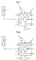
- the ventilation controlling apparatus comprises an extractor fan [1] mounted in an external wall or window of a conventional domestic dwelling, close to the moisture sources in either the kitchen or bathroom.
- the extractor fan [1] is electrically powered and connected by wire to the output relay [9] of the control unit [11].
- the control unit [11] includes a microprocessor [6], probe sense amplifier [3], probe log converter [4], analogue to digital converter [5], Relay [9] and LED status indicator [8], and is connected to thermistor [7] and humidity sensor [2].
- the sensed Humidity is continually supplied to the microprocessor via probe sense amplifier [3], the probe log converter [4] and A to D converter [5].
- the microprocessor programming converts the Humidity readings to Absolute humidity with as required the temperature input from the thermistor, readings from the humidity sensor are averaged over 30 seconds this average value is then supplied for memory storage, these readings are then stored for two hours the average over this two hour period is used as the base reference.
- the base reference is updated every two hours with the average of the absolute humidity reading taken over the preceding two hour period. During activation periods of the extractor fan humidity readings for the base reference are suspended, this is to avoid spurious ambient readings during the desiccation period.
- a threshold level of absolute humidity above the base reference is chosen sufficiently high to avoid ambient humidity variations that could occur over a two hour period but low enough to activate the ventilator with moisture production.
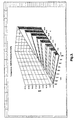
- the Absolute Humidity threshold level is altered at different temperatures, as shown in Table 1 below.
- controller can be set to operate for double the period expressed in Table 2 when used with less efficient ventilation systems such as air heat recovery and positive air pressure systems. This is achieved by cutting link [12] which adjusts the microprocessor program.
- Relative Humidity as Figure 1, Operation as Absolute Humidity Controller without thermister input.
- the %RH is stored over the two hour period and used as the base reference (being updated every two hours).
- the base reference is compared with humidity samples taken after 3 minutes of ventilator operation (this sample taken over 30 seconds and then averaged).
- the processor operates the ventilator by relay 9 when certain absolute humidity condition are met.
- the processor calculates the absolute humidity the average value over a given period is used as a reference, when the absolute value of humidity increases above a given threshold above this reference ventilation apparatus 1 is activated.
- a further humidity reading after a given time is taken while the ventilation apparatus 1 has been activated, the humidity difference from the reference and this further reading provides the basis to calculate the actual total running time of the ventilation apparatus 1.
- Thermistor 7 and pressure transducer 10 are connected to microprocessor 6.
- the processor operates the ventilator by relay 9 when certain specific humidity condition are met.
- the processor calculates the specific humidity the average value over a given period is used as a reference, when the absolute value of humidity increases above a given threshold above this reference ventilation apparatus 1 is activated.
- a further humidity reading after a given time is taken while the ventilation apparatus 1 has been activated, the humidity difference from the reference and this further reading provides the basis to calculate the actual total running time of the ventilation apparatus 1.
Landscapes
- Engineering & Computer Science (AREA)
- Mechanical Engineering (AREA)
- Signal Processing (AREA)
- Physics & Mathematics (AREA)
- General Engineering & Computer Science (AREA)
- Chemical & Material Sciences (AREA)
- Combustion & Propulsion (AREA)
- Fuzzy Systems (AREA)
- Mathematical Physics (AREA)
- General Physics & Mathematics (AREA)
- Automation & Control Theory (AREA)
- Ventilation (AREA)
- Air Conditioning Control Device (AREA)
- Investigating Or Analyzing Materials Using Thermal Means (AREA)
- Flow Control (AREA)
Claims (12)
- Appareil de contrôle de l'humidité de l'air comprenant un capteur d'humidité (2) actionnable pour produire un signal électrique, dont le niveau est déterminé par l'humidité de l'air mesuré par le capteur, et un moyen formant microprocesseur (6) couplé au capteur afin de recevoir ledit signal, dans lequel le moyen formant microprocesseur est organisé pour fournir un signal de contrôle de l'humidité de l'air sortant quand l'humidité mesurée excède d'un montant prédéterminé une base de référence de l'humidité, caractérisé en ce que le microprocesseur enregistre les valeurs d'humidité indiquées par le signal du capteur, calcule une moyenne sur une durée, et utilise la moyenne calculée comme ladite base de référence de l'humidité.
- Appareil de contrôle de l'humidité de l'air selon la revendication 1, caractérisé en outre en ce que le moyen formant microprocesseur compare une seconde lecture de l'humidité, effectuée après une période significative suivant la fourniture dudit signal de contrôle de l'humidité de l'air sortant, à la base de référence de l'humidité et la différence des niveaux d'humidité donne une base de calcul pour la durée du signal de contrôle de l'humidité de l'air sortant.
- Appareil de contrôle de l'humidité de l'air selon la revendication 2, dans lequel la seconde lecture de l'humidité est effectuée dans une petite période d'échantillonnage après ladite période suivant la fourniture du signal de contrôle de l'humidité de l'air sortant.
- Appareil de contrôle de l'humidité de l'air selon l'une des revendications précédentes, caractérisé en outre en ce que ledit moyen formant microprocesseur enregistre et fait la moyenne de l'humidité sur de petites périodes d'échantillonnage, compile la moyenne des lectures d'humidité effectuées dans ces petites périodes d'échantillonnage sur une plus longue période, dont la moyenne sert de base de référence de l'humidité, et quand la valeur de l'humidité dans la petite période d'échantillonnage actuelle excède d'un seuil prédéterminé la base de référence de l'humidité, ledit moyen formant microprocesseur est organisé pour fournir ledit signal de contrôle de l'humidité de l'air sortant.
- Appareil de contrôle de l'humidité de l'air selon l'une des revendications précédentes, caractérisé en outre en ce que le signal de contrôle de l'humidité de l'air sortant est adapté pour désactiver l'humidité de l'air si l'humidité mesurée diminue jusqu'à la base de référence de l'humidité.
- Appareil de contrôle de l'humidité de l'air selon l'une des revendications précédentes, dans lequel ledit moyen formant microprocesseur est organisé pour détecter, enregistrer et calculer sur la base de l'Humidité Absolue, les lectures d'humidité provenant du capteur d'humidité (2), étant ajustées comme requis par les lectures d'un capteur de température (7) pour concorder avec les caractéristiques du capteur d'humidité utilisé.
- Appareil de contrôle de l'humidité de l'air selon l'une quelconque des revendications 1 à 5, dans lequel le moyen formant microprocesseur est organisé pour détecter, enregistrer et calculer sur la base de l'Humidité Relative en pour-cent, les lectures d'humidité provenant du capteur d'humidité (2), étant ajustées comme requis par les lectures provenant d'un capteur de température (7) pour concorder avec les caractéristiques du capteur d'humidité utilisé.
- Appareil de contrôle de l'humidité de l'air selon l'une quelconque des revendications 1 à 5, dans lequel le moyen formant microprocesseur est organisé pour détecter, enregistrer et calculer sur la base de l'Humidité Spécifique, les lectures d'humidité provenant du capteur d'humidité (2), étant ajustées comme requis par les lectures provenant d'un capteur de température (7) et d'un capteur de pression de l'air (10) pour concorder avec les caractéristiques du capteur d'humidité utilisé.
- Appareil de contrôle de l'humidité de l'air comprenant un capteur d'humidité (2) actionnable pour produire un signal électrique dont le niveau est déterminé par l'humidité de l'air mesuré par le capteur, et un moyen formant microprocesseur (6) couplé au capteur afin de recevoir ledit signal, dans lequel le moyen formant microprocesseur est organisé pour fournir un signal de contrôle de l'humidité de l'air sortant quand l'humidité mesurée excède d'un montant prédéterminé une base de référence de l'humidité, caractérisé en ce que le microprocesseur enregistre les valeurs d'humidité indiquées par le signal du capteur, dérive des données à partir desdites valeurs d'humidité et utilise les données dérivées pour compiler ladite base de référence de l'humidité
- Appareil de contrôle de l'humidité de l'air selon la revendication 9, dans lequel la fourniture du signal de contrôle de l'humidité de l'air sortant est dépendante d'une base de référence de l'humidité compilée à partir à la fois de la valeur de référence moyenne enregistrée de l'humidité relative et de la valeur captée actuellement de l'humidité relative.
- Appareil de contrôle de l'humidité de l'air selon l'une quelconque des revendications précédentes, dans lequel le signal de contrôle sortant est fourni à un appareil de ventilation.
- Appareil pour modifier le taux d'humidité de l'air dans un bâtiment ou une salle, ayant des moyens de contrôle comprenant un appareil de contrôle de l'humidité de l'air selon l'une des revendications précédentes.
Applications Claiming Priority (7)
| Application Number | Priority Date | Filing Date | Title |
|---|---|---|---|
| GBGB9616699.6A GB9616699D0 (en) | 1996-08-09 | 1996-08-09 | Ventilation controlling apparatus |
| GB9616699 | 1996-08-09 | ||
| GBGB9623525.4A GB9623525D0 (en) | 1996-08-09 | 1996-11-11 | Optimisation for ventilation controlling apparatus |
| GB9623525 | 1996-11-11 | ||
| GB9627135 | 1996-12-31 | ||
| GB9627135A GB2316188B (en) | 1996-08-09 | 1996-12-31 | Ventilation controlling apparatus |
| PCT/GB1997/002155 WO1998007083A1 (fr) | 1996-08-09 | 1997-08-08 | Regulation de ventilation |
Publications (2)
| Publication Number | Publication Date |
|---|---|
| EP0917677A1 EP0917677A1 (fr) | 1999-05-26 |
| EP0917677B1 true EP0917677B1 (fr) | 2002-12-11 |
Family
ID=27268423
Family Applications (1)
| Application Number | Title | Priority Date | Filing Date |
|---|---|---|---|
| EP97935687A Expired - Lifetime EP0917677B1 (fr) | 1996-08-09 | 1997-08-08 | Regulation de ventilation |
Country Status (7)
| Country | Link |
|---|---|
| US (1) | US6230980B1 (fr) |
| EP (1) | EP0917677B1 (fr) |
| JP (1) | JP2001500291A (fr) |
| AT (1) | ATE229664T1 (fr) |
| CA (1) | CA2262657C (fr) |
| DE (1) | DE69717821D1 (fr) |
| WO (1) | WO1998007083A1 (fr) |
Families Citing this family (44)
| Publication number | Priority date | Publication date | Assignee | Title |
|---|---|---|---|---|
| US7097111B2 (en) * | 2000-07-21 | 2006-08-29 | Gun Valley Temperature Controls Llc | Environmental control system and method for storage buildings |
| US6467695B1 (en) * | 2000-07-21 | 2002-10-22 | Gun Valley Temperature Controls Llc | Environmental control system and method for storage buildings |
| US7651034B2 (en) * | 2000-08-04 | 2010-01-26 | Tjernlund Products, Inc. | Appliance room controller |
| US6726111B2 (en) * | 2000-08-04 | 2004-04-27 | Tjernlund Products, Inc. | Method and apparatus for centrally controlling environmental characteristics of multiple air systems |
| CA2435934A1 (fr) * | 2002-09-12 | 2004-03-12 | 1045929 Ontario Limited | Ejecteur et deflecteur de plaques de gazon en mauvais etat |
| US20070209653A1 (en) * | 2003-03-06 | 2007-09-13 | Exhausto, Inc. | Pressure Controller for a Mechanical Draft System |
| US7275533B2 (en) * | 2003-03-06 | 2007-10-02 | Exhausto, Inc. | Pressure controller for a mechanical draft system |
| WO2004090653A1 (fr) * | 2003-04-05 | 2004-10-21 | Ebac Limited | Systeme de commande de deshumidificateur |
| FR2869677B1 (fr) * | 2004-04-30 | 2006-12-22 | Brandt Ind Sas | Dispositif de controle du taux d'humidite dans une cave a vin electrodomestique |
| US20050277381A1 (en) * | 2004-06-15 | 2005-12-15 | Chinmoy Banerjee | System to control environmental conditions in a living space |
| US20060213000A1 (en) * | 2005-03-25 | 2006-09-28 | Kimble Christopher J | Automatic energy-efficient bathroom exhaust fan controller |
| JP4052318B2 (ja) * | 2005-05-24 | 2008-02-27 | ダイキン工業株式会社 | 空調システム |
| US7699051B2 (en) * | 2005-06-08 | 2010-04-20 | Westen Industries, Inc. | Range hood |
| US20060286922A1 (en) * | 2005-06-14 | 2006-12-21 | Clifford Roux | Exhaust fan controller |
| DE102006020003A1 (de) * | 2006-04-26 | 2007-10-31 | Herbert Kannegiesser Gmbh | Verfahren zur Rückgewinnung der von Wäschereimaschinen abgegebenen Wärmeenergie |
| US7758408B2 (en) * | 2006-06-01 | 2010-07-20 | Ventotech Ab | Dehumidifying ventilation and regulation of airflow in enclosed structures |
| SE0602058L (sv) * | 2006-09-29 | 2008-03-30 | Lindenstone Innovation Ab | En metod och en anordning för att skydda ett utrymme mot fuktskador |
| US8172154B1 (en) * | 2007-02-22 | 2012-05-08 | Figley Donald A | Humidity monitoring and alarm system for unattended detection of building moisture management problems |
| US7690583B2 (en) * | 2007-08-27 | 2010-04-06 | Spring Loop Quail Limited Partnership | Humidity sensor and fan control device |
| US20100078494A1 (en) * | 2008-10-01 | 2010-04-01 | Marco Mularoni | Humidity-activated ventilation system switch |
| US8640970B2 (en) * | 2009-05-27 | 2014-02-04 | Direct Success, Llc | Air quality control system |
| EP2524175A4 (fr) | 2010-01-13 | 2014-09-24 | Gtr Technologies Inc | Système et procédé de commande de ventilation |
| SE534370C2 (sv) * | 2010-04-29 | 2011-07-26 | Dryvent Solutions Of Scandinavia Ab | System och metod för att ventilera ett avgränsat utrymme |
| GB2485354B (en) * | 2010-11-09 | 2017-11-08 | Greenwood Air Man Ltd | Humidity control system |
| JP5966490B2 (ja) * | 2012-03-23 | 2016-08-10 | 株式会社リコー | 被記録媒体の表面改質装置、インクジェット式プリンタ |
| CN103810075A (zh) * | 2012-11-15 | 2014-05-21 | 鸿富锦精密工业(深圳)有限公司 | 湿度侦测电路 |
| US9976764B2 (en) | 2014-05-28 | 2018-05-22 | Leviton Manufacturing Co., Inc. | Apparatus and methods for controlling a ventilation mechanism |
| US9874366B2 (en) | 2014-07-30 | 2018-01-23 | Research Products Corporation | System and method for adjusting fractional on-time and cycle time to compensate for weather extremes and meet ventilation requirements |
| US20160117900A1 (en) * | 2014-10-27 | 2016-04-28 | Ian Hibbitt | Methods for detecting fires in biomass storage systems |
| SE542055C2 (en) * | 2015-04-29 | 2020-02-18 | Egain Sweden Ab | Method for determining ventilation rate within an indoor environment |
| US10760804B2 (en) | 2017-11-21 | 2020-09-01 | Emerson Climate Technologies, Inc. | Humidifier control systems and methods |
| WO2019204790A1 (fr) | 2018-04-20 | 2019-10-24 | Emerson Climate Technologies, Inc. | Systèmes et procédés avec seuils d'atténuation variable |
| WO2019204779A1 (fr) | 2018-04-20 | 2019-10-24 | Emerson Climate Technologies, Inc. | Systèmes et procédés de surveillance de la qualité de l'air intérieur et de l'occupant |
| WO2019204785A1 (fr) | 2018-04-20 | 2019-10-24 | Emerson Climate Technologies, Inc. | Système de commande de ventilateur à base de matière particulaire |
| US12078373B2 (en) | 2018-04-20 | 2024-09-03 | Copeland Lp | Systems and methods for adjusting mitigation thresholds |
| US11486593B2 (en) | 2018-04-20 | 2022-11-01 | Emerson Climate Technologies, Inc. | Systems and methods with variable mitigation thresholds |
| US11371726B2 (en) | 2018-04-20 | 2022-06-28 | Emerson Climate Technologies, Inc. | Particulate-matter-size-based fan control system |
| WO2019204789A1 (fr) | 2018-04-20 | 2019-10-24 | Emerson Climate Technologies, Inc. | Systèmes et procédés d'étalonnage de capteur de qualité d'air intérieur |
| WO2019204786A1 (fr) | 2018-04-20 | 2019-10-24 | Emerson Climate Technologies, Inc. | Système informatisé d'évaluation de filtre hvac |
| WO2019204792A1 (fr) | 2018-04-20 | 2019-10-24 | Emerson Climate Technologies, Inc. | Commande coordonnée de dispositifs et de systèmes autonomes et de qualité d'air intérieur de bâtiment |
| US12018852B2 (en) | 2018-04-20 | 2024-06-25 | Copeland Comfort Control Lp | HVAC filter usage analysis system |
| WO2020112981A1 (fr) | 2018-11-29 | 2020-06-04 | Broan-Nutone Llc | Système intelligent de ventilation d'air intérieur |
| DK3816529T3 (en) * | 2019-10-31 | 2022-02-14 | Dyseco Holding B V | Control system for climate conditioning of a building zone |
| US12074436B2 (en) | 2022-01-07 | 2024-08-27 | Leviton Manufacturing Co., Inc. | Controlling power to a load based on sensed environmental conditions |
Family Cites Families (11)
| Publication number | Priority date | Publication date | Assignee | Title |
|---|---|---|---|---|
| US4312189A (en) * | 1978-06-09 | 1982-01-26 | Industrial Air, Inc. | Air condition system controlled responsive to the absolute humidity of air in a designated treated space |
| JPS63161334A (ja) | 1986-12-24 | 1988-07-05 | Toshiba Corp | 換気扇の運転装置 |
| US4700887A (en) * | 1986-12-29 | 1987-10-20 | Cornell Research Foundation, Inc. | Environmental control system for poultry houses |
| GB8720060D0 (en) | 1987-08-25 | 1987-09-30 | System Controls Management Ltd | Humidity & ventilation control |
| US5232152A (en) | 1991-10-30 | 1993-08-03 | Tsang Richard W B | Range hood fan with atmospheric humidity sensor |
| US5351855A (en) * | 1992-04-02 | 1994-10-04 | Honeywell Inc. | Humidistat reset control |
| US5346129A (en) * | 1993-05-17 | 1994-09-13 | Honeywell Inc. | Indoor climate controller system adjusting both dry-bulb temperature and wet-bulb or dew point temperature in the enclosure |
| US5407129A (en) * | 1993-08-30 | 1995-04-18 | Georgia Tech Research Corporation | Poultry environmental control systems and methods |
| US5428964A (en) * | 1994-01-10 | 1995-07-04 | Tec-Way Air Quality Products Inc. | Control for air quality machine |
| EP0797793A4 (fr) * | 1994-09-19 | 1999-01-07 | Georgia Tech Res Inst | Procedes et systemes de regulation de l'environnement de poulaillers d'elevage |
| US5675979A (en) * | 1996-03-01 | 1997-10-14 | Honeywell Inc. | Enthalpy based thermal comfort controller |
-
1997
- 1997-08-08 US US09/242,085 patent/US6230980B1/en not_active Expired - Lifetime
- 1997-08-08 JP JP10509502A patent/JP2001500291A/ja not_active Ceased
- 1997-08-08 CA CA002262657A patent/CA2262657C/fr not_active Expired - Fee Related
- 1997-08-08 AT AT97935687T patent/ATE229664T1/de not_active IP Right Cessation
- 1997-08-08 WO PCT/GB1997/002155 patent/WO1998007083A1/fr not_active Ceased
- 1997-08-08 EP EP97935687A patent/EP0917677B1/fr not_active Expired - Lifetime
- 1997-08-08 DE DE69717821T patent/DE69717821D1/de not_active Expired - Lifetime
Also Published As
| Publication number | Publication date |
|---|---|
| ATE229664T1 (de) | 2002-12-15 |
| EP0917677A1 (fr) | 1999-05-26 |
| DE69717821D1 (de) | 2003-01-23 |
| CA2262657C (fr) | 2006-05-16 |
| CA2262657A1 (fr) | 1998-02-19 |
| US6230980B1 (en) | 2001-05-15 |
| JP2001500291A (ja) | 2001-01-09 |
| WO1998007083A1 (fr) | 1998-02-19 |
Similar Documents
| Publication | Publication Date | Title |
|---|---|---|
| EP0917677B1 (fr) | Regulation de ventilation | |
| US6186407B1 (en) | Humidity control based on an estimation using heating plant cycle, of inside window surface temperature | |
| US6776817B2 (en) | Airflow sensor, system and method for detecting airflow within an air handling system | |
| US8352082B2 (en) | Methods and apparatuses for displaying energy savings from an HVAC system | |
| US5717609A (en) | System and method for energy measurement and verification with constant baseline reference | |
| KR890006098A (ko) | 히터 에너지 계수기를 사용한 온도 감지 고장 검출 장치 | |
| EP3126751B1 (fr) | Dispositif et procédé de ventilation d'extraction | |
| AU2011253568A1 (en) | Laundry dryer with environmental temperature sensor | |
| US20080180258A1 (en) | Fire Detectors with Environmental Data Input | |
| WO2011088270A4 (fr) | Système et procédé de commande de ventilation | |
| Li et al. | Measurement of residential HVAC system runtime | |
| US4793553A (en) | Infrared thermostat control | |
| JP2000097480A5 (fr) | ||
| WO1984003976A1 (fr) | Dispositif detecteur d'incendie | |
| GB2316188A (en) | Controlling ventilation apparatus by humidity measurement | |
| RU2003114860A (ru) | Болометрический гигрометр, плита или печь с его использованием и способ регулирования плиты или печи | |
| CN112378035B (zh) | 空调温度传感器的采样值处理方法及装置 | |
| KR910008824B1 (ko) | 옥외주변 온도측정 시스템 | |
| CN214748135U (zh) | 温湿度传感器防凝露装置 | |
| JPH0326448Y2 (fr) | ||
| EP3098528A1 (fr) | Procédé pour déterminer la vitesse de ventilation dans un environnement intérieur | |
| Kalogiros et al. | Fast-response humidity measurements with the psychrometric method | |
| Madsen | Measurement and control of thermal comfort in passive solar systems | |
| JPS62189596A (ja) | 蒸気漏れ警報システム | |
| JPH02157555A (ja) | 温湿度測定手段の異常検出装置 |
Legal Events
| Date | Code | Title | Description |
|---|---|---|---|
| PUAI | Public reference made under article 153(3) epc to a published international application that has entered the european phase |
Free format text: ORIGINAL CODE: 0009012 |
|
| 17P | Request for examination filed |
Effective date: 19990225 |
|
| AK | Designated contracting states |
Kind code of ref document: A1 Designated state(s): AT BE CH DE DK ES FI FR GB GR IE IT LI NL PT SE |
|
| GRAG | Despatch of communication of intention to grant |
Free format text: ORIGINAL CODE: EPIDOS AGRA |
|
| 17Q | First examination report despatched |
Effective date: 20010705 |
|
| GRAG | Despatch of communication of intention to grant |
Free format text: ORIGINAL CODE: EPIDOS AGRA |
|
| GRAG | Despatch of communication of intention to grant |
Free format text: ORIGINAL CODE: EPIDOS AGRA |
|
| GRAH | Despatch of communication of intention to grant a patent |
Free format text: ORIGINAL CODE: EPIDOS IGRA |
|
| GRAH | Despatch of communication of intention to grant a patent |
Free format text: ORIGINAL CODE: EPIDOS IGRA |
|
| GRAH | Despatch of communication of intention to grant a patent |
Free format text: ORIGINAL CODE: EPIDOS IGRA |
|
| GRAA | (expected) grant |
Free format text: ORIGINAL CODE: 0009210 |
|
| AK | Designated contracting states |
Kind code of ref document: B1 Designated state(s): AT BE CH DE DK ES FI FR GB GR IE IT LI NL PT SE |
|
| PG25 | Lapsed in a contracting state [announced via postgrant information from national office to epo] |
Ref country code: NL Free format text: LAPSE BECAUSE OF FAILURE TO SUBMIT A TRANSLATION OF THE DESCRIPTION OR TO PAY THE FEE WITHIN THE PRESCRIBED TIME-LIMIT Effective date: 20021211 Ref country code: LI Free format text: LAPSE BECAUSE OF FAILURE TO SUBMIT A TRANSLATION OF THE DESCRIPTION OR TO PAY THE FEE WITHIN THE PRESCRIBED TIME-LIMIT Effective date: 20021211 Ref country code: IT Free format text: LAPSE BECAUSE OF FAILURE TO SUBMIT A TRANSLATION OF THE DESCRIPTION OR TO PAY THE FEE WITHIN THE PRESCRIBED TIME-LIMIT;WARNING: LAPSES OF ITALIAN PATENTS WITH EFFECTIVE DATE BEFORE 2007 MAY HAVE OCCURRED AT ANY TIME BEFORE 2007. THE CORRECT EFFECTIVE DATE MAY BE DIFFERENT FROM THE ONE RECORDED. Effective date: 20021211 Ref country code: GR Free format text: LAPSE BECAUSE OF FAILURE TO SUBMIT A TRANSLATION OF THE DESCRIPTION OR TO PAY THE FEE WITHIN THE PRESCRIBED TIME-LIMIT Effective date: 20021211 Ref country code: FR Free format text: LAPSE BECAUSE OF NON-PAYMENT OF DUE FEES Effective date: 20021211 Ref country code: FI Free format text: LAPSE BECAUSE OF FAILURE TO SUBMIT A TRANSLATION OF THE DESCRIPTION OR TO PAY THE FEE WITHIN THE PRESCRIBED TIME-LIMIT Effective date: 20021211 Ref country code: CH Free format text: LAPSE BECAUSE OF FAILURE TO SUBMIT A TRANSLATION OF THE DESCRIPTION OR TO PAY THE FEE WITHIN THE PRESCRIBED TIME-LIMIT Effective date: 20021211 Ref country code: BE Free format text: LAPSE BECAUSE OF FAILURE TO SUBMIT A TRANSLATION OF THE DESCRIPTION OR TO PAY THE FEE WITHIN THE PRESCRIBED TIME-LIMIT Effective date: 20021211 Ref country code: AT Free format text: LAPSE BECAUSE OF FAILURE TO SUBMIT A TRANSLATION OF THE DESCRIPTION OR TO PAY THE FEE WITHIN THE PRESCRIBED TIME-LIMIT Effective date: 20021211 |
|
| REF | Corresponds to: |
Ref document number: 229664 Country of ref document: AT Date of ref document: 20021215 Kind code of ref document: T |
|
| REG | Reference to a national code |
Ref country code: GB Ref legal event code: FG4D |
|
| REG | Reference to a national code |
Ref country code: CH Ref legal event code: EP |
|
| RAP4 | Party data changed (patent owner data changed or rights of a patent transferred) |
Owner name: RAY HUDSON LIMITED |
|
| REG | Reference to a national code |
Ref country code: IE Ref legal event code: FG4D |
|
| REF | Corresponds to: |
Ref document number: 69717821 Country of ref document: DE Date of ref document: 20030123 |
|
| PG25 | Lapsed in a contracting state [announced via postgrant information from national office to epo] |
Ref country code: SE Free format text: LAPSE BECAUSE OF FAILURE TO SUBMIT A TRANSLATION OF THE DESCRIPTION OR TO PAY THE FEE WITHIN THE PRESCRIBED TIME-LIMIT Effective date: 20030311 Ref country code: PT Free format text: LAPSE BECAUSE OF FAILURE TO SUBMIT A TRANSLATION OF THE DESCRIPTION OR TO PAY THE FEE WITHIN THE PRESCRIBED TIME-LIMIT Effective date: 20030311 Ref country code: DK Free format text: LAPSE BECAUSE OF FAILURE TO SUBMIT A TRANSLATION OF THE DESCRIPTION OR TO PAY THE FEE WITHIN THE PRESCRIBED TIME-LIMIT Effective date: 20030311 |
|
| PG25 | Lapsed in a contracting state [announced via postgrant information from national office to epo] |
Ref country code: DE Free format text: LAPSE BECAUSE OF FAILURE TO SUBMIT A TRANSLATION OF THE DESCRIPTION OR TO PAY THE FEE WITHIN THE PRESCRIBED TIME-LIMIT Effective date: 20030312 |
|
| NLV1 | Nl: lapsed or annulled due to failure to fulfill the requirements of art. 29p and 29m of the patents act | ||
| PG25 | Lapsed in a contracting state [announced via postgrant information from national office to epo] |
Ref country code: ES Free format text: LAPSE BECAUSE OF FAILURE TO SUBMIT A TRANSLATION OF THE DESCRIPTION OR TO PAY THE FEE WITHIN THE PRESCRIBED TIME-LIMIT Effective date: 20030627 |
|
| REG | Reference to a national code |
Ref country code: CH Ref legal event code: PL |
|
| PLBE | No opposition filed within time limit |
Free format text: ORIGINAL CODE: 0009261 |
|
| STAA | Information on the status of an ep patent application or granted ep patent |
Free format text: STATUS: NO OPPOSITION FILED WITHIN TIME LIMIT |
|
| EN | Fr: translation not filed | ||
| 26N | No opposition filed |
Effective date: 20030912 |
|
| PGFP | Annual fee paid to national office [announced via postgrant information from national office to epo] |
Ref country code: IE Payment date: 20100730 Year of fee payment: 14 |
|
| PGFP | Annual fee paid to national office [announced via postgrant information from national office to epo] |
Ref country code: GB Payment date: 20100827 Year of fee payment: 14 |
|
| GBPC | Gb: european patent ceased through non-payment of renewal fee |
Effective date: 20110808 |
|
| REG | Reference to a national code |
Ref country code: IE Ref legal event code: MM4A |
|
| PG25 | Lapsed in a contracting state [announced via postgrant information from national office to epo] |
Ref country code: IE Free format text: LAPSE BECAUSE OF NON-PAYMENT OF DUE FEES Effective date: 20110808 |
|
| PG25 | Lapsed in a contracting state [announced via postgrant information from national office to epo] |
Ref country code: GB Free format text: LAPSE BECAUSE OF NON-PAYMENT OF DUE FEES Effective date: 20110808 |