EP0917854A2 - Non-contact non-invasive measuring method and apparatus - Google Patents
Non-contact non-invasive measuring method and apparatus Download PDFInfo
- Publication number
- EP0917854A2 EP0917854A2 EP98120518A EP98120518A EP0917854A2 EP 0917854 A2 EP0917854 A2 EP 0917854A2 EP 98120518 A EP98120518 A EP 98120518A EP 98120518 A EP98120518 A EP 98120518A EP 0917854 A2 EP0917854 A2 EP 0917854A2
- Authority
- EP
- European Patent Office
- Prior art keywords
- probe
- physical quantity
- measuring
- measured
- orientation
- Prior art date
- Legal status (The legal status is an assumption and is not a legal conclusion. Google has not performed a legal analysis and makes no representation as to the accuracy of the status listed.)
- Withdrawn
Links
- 238000000034 method Methods 0.000 title claims description 26
- 239000000523 sample Substances 0.000 claims abstract description 82
- 238000005259 measurement Methods 0.000 claims description 49
- 108091008695 photoreceptors Proteins 0.000 claims description 13
- 230000003287 optical effect Effects 0.000 claims description 10
- 230000001678 irradiating effect Effects 0.000 claims description 8
- 230000007246 mechanism Effects 0.000 claims description 7
- 230000008569 process Effects 0.000 description 7
- 230000005540 biological transmission Effects 0.000 description 3
- 230000003340 mental effect Effects 0.000 description 3
- WQZGKKKJIJFFOK-GASJEMHNSA-N Glucose Natural products OC[C@H]1OC(O)[C@H](O)[C@@H](O)[C@@H]1O WQZGKKKJIJFFOK-GASJEMHNSA-N 0.000 description 2
- 238000010586 diagram Methods 0.000 description 2
- 239000008103 glucose Substances 0.000 description 2
- 208000003443 Unconsciousness Diseases 0.000 description 1
- 208000037265 diseases, disorders, signs and symptoms Diseases 0.000 description 1
- 239000006185 dispersion Substances 0.000 description 1
- 238000000605 extraction Methods 0.000 description 1
- 230000006872 improvement Effects 0.000 description 1
- 230000003993 interaction Effects 0.000 description 1
- 230000031700 light absorption Effects 0.000 description 1
- 238000000491 multivariate analysis Methods 0.000 description 1
- 230000004044 response Effects 0.000 description 1
Images



Classifications
-
- A—HUMAN NECESSITIES
- A61—MEDICAL OR VETERINARY SCIENCE; HYGIENE
- A61B—DIAGNOSIS; SURGERY; IDENTIFICATION
- A61B5/00—Measuring for diagnostic purposes; Identification of persons
- A61B5/0059—Measuring for diagnostic purposes; Identification of persons using light, e.g. diagnosis by transillumination, diascopy, fluorescence
- A61B5/0073—Measuring for diagnostic purposes; Identification of persons using light, e.g. diagnosis by transillumination, diascopy, fluorescence by tomography, i.e. reconstruction of 3D images from 2D projections
Definitions
- the present invention relates to a method of non-invasively measuring a physical quantity such as a component concentration in a living body, such as a blood-sugar level in a human body, in a non-contact state and an apparatus therefor.
- a measuring apparatus In order to measure a physical quantity in a living body, a measuring apparatus must interact with the surface of the measured body in some form. Also, in case of making measurements through the principle of absorption of light, interaction such as the application of light to the living body is unavoidable. In a measuring method carried out by directly bringing a probe with a sensor into contact with the living body, such contact exerts remarkable influence on the measured object, and hence a measurement error is increased unless such influence is suppressed to a minimum. Specifically, when the measured object is a conscious living thing such as a human, he is not only physically but also mentally influenced by the measuring method. Furthermore, the influence varies with the difference between the equilibrium state of the human and the state of the probe. There is the apprehension that a process for adjusting the equilibrium to a new state causes a disturbance on the measurement of the physical quantity to influence the measured value depending on the difference between the states, whether the human himself is conscious or unconscious.
- an obtained signal is extremely weak by nature and physical or mental influence disorders the measured value to deteriorate a signal-to-noise ratio and causes difficulty in extraction of the signal if the measurement is made in a contact state.
- Such influence resulting from the contact is considered as one of the factors hindering improvement in accuracy of non-invasive glucose measurement at present.
- the method of minimizing a measurement error resulting from such physical or mental influence is adapted to arrange the measured object in a space not to be in contact with the probe for measurements by irradiating the measured object with light from a measuring apparatus.
- the object of the present invention is to obtain reproducible measured data by arranging a measured object in a space in a state not in contact with a probe and determining a relative position thereof with respect to a measuring apparatus.
- the present invention it is preferable to make measurements in such an ordinary state that a measured object, for example a human body, is already at thermal equilibrium under the room temperature.
- the present invention is adapted to set a measured portion in a prescribed space of a measuring apparatus in a non-contact state for determining the orientation of applied light and relative positional relation between a probe and the measured object, and making measurements regularly on a constant position and in a constant orientation.
- a measured portion in a prescribed space of a measuring apparatus in a non-contact state for determining the orientation of applied light and relative positional relation between a probe and the measured object, and making measurements regularly on a constant position and in a constant orientation.
- the image indicating the measured portion on the measured object, the distance between the image and a sensing position, and the orientation of a physical quantity measuring apparatus with respect to the measured portion in measurement are previously registered for measurements by determining the position and the orientation of the physical quantity measuring apparatus through the following steps.
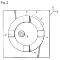
- a surface perpendicularly intersecting with a ring surface through the center of a ring-shaped probe shown in Fig. 2 is an X-Y plane and an axis perpendicularly intersecting with the X-Y plane through the center of the probe is a Z-axis
- the intersection point between the central circle of the ring and the Z-axis is referred to as the sensing position in the present invention.
- the previously registered distance (Z 0 ) up to the measured portion is preferably equal to the radius of the ring-shaped probe. In this case, the measured portion comes to the center of the ring forming the probe. Also, when the ring forming the probe is so rotated that the measured portion is along the previously registered orientation ( ⁇ 0 ), the position (X 0 , Y 0 ) of the measured portion already determined in the step (A) remains unchanged.
- the orientation of measurement indicates the angle formed by a beam for the measuring of the physical quantity and the normal direction of the measured portion.
- One of the orientations of measurement which can be determined in various ways, is so determined that the orientation angle is zero.
- the orientation at the zero orientation angle referred to as a reference orientation, can be sensed through the characteristics of the shape of the measured object for the measuring of the physical quantity in the reference orientation.
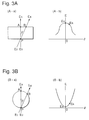
- the measured object has a rectangular sectional shape in a Y-Z plane, for example, the energy of transmitted light is maximized at the zero orientation angle as shown in Fig. 3A.
- the measured object has a circular sectional shape in the Y-Z plane, for example, the energy of the transmitted light is minimized at the zero orientation angle as shown in Fig. 3B.
- the sectional shape of the measured object in the Z-Y plane is not restricted to a rectangular or circular one but the reference orientation can be sensed through the characteristics of the distribution waveform of transmission energy also when the measured object has still another sectional shape.
- the physical quantity may be measured not in the reference orientation but in another orientation, which can be sensed from the waveform of the transmission energy.
- the orientation can be determined not through the waveform of the transmission energy itself but through the primary, secondary or higher order differential waveform thereof.
- a measuring apparatus comprises a ring-shaped probe 2 which is set around a space where a measured portion 9 is arranged in a non-contact manner, sensors including positioning means 4, distance measuring means 6, orientation determination means 8 and a physical quantity measuring apparatus 10 which are arranged along the ring of the probe 2 and inwardly mounted thereon, a support mechanism (not shown) for the probe 2, a position control part (not shown), and a data processor (not shown), as shown in Fig. 2.
- the support mechanism for the probe 2 supports the probe 2 to be movable in the X-, Y- and Z-axis directions and rotatable in the plane including the ring.
- the position control part stores the position of an image indicating the measured portion 9, the distance between the measured portion 9 and a sensing position located on the intersection point between the ring and the Z-axis in measurement, and the orientation of the physical quantity measuring apparatus 10 with respect to the measured portion 9 in measurement for arranging the positioning means 4 on the sensing position with respect to the measured portion 9, which is arranged in a prescribed space in a non-contact state, and adjusting the position of the probe 2 by controlling the support mechanism in the X- and Y-axis directions when the positioning means 4 senses the previously registered image of the measured portion 9, so that the position of the sensed image coincides with that of the registered image, arranging the distance measuring means 6 on the sensing position, adjusting the position of the probe 2 by controlling the support mechanism in the Z-axis direction so that the distance up to the measured portion 9 sensed by the distance measuring means 6 is equal to the previously registered distance, arranging the orientation determination means 8 on the sensing position, determining such a position that the orientation of the measured portion 9 sensed by the orientation determination
- the data processor calculates the physical quantity from a sensing signal of the physical quantity measuring apparatus 10 positioned by the position control part.
- the steps (A) to (D) may be repeated in every physical quantity measurement, for measuring the physical quantity a plurality of times.
- the measured object which is brought into a non-contact state, cannot be fixed over a long time. Therefore, the physical quantity can be measured regularly under constant measuring conditions by adjusting the relative positions and the orientations of the measured portion and the physical quantity measuring apparatus in every physical quantity measurement. Furthermore, the physical quantity can be measured under constant measuring conditions even if the measured object is in a moving state.
- a preliminary positioning apparatus to arrange the measured portion 9 in the prescribed space so that the preliminary positioning apparatus is removed after positioning and the measured portion 9 is arranged in a spatially non-contact manner, as shown in the upper portion of Fig. 1. Thereafter, the sensing position of the probe 2, the measured area (distance) and the measuring orientation are determined with respect to the measured portion 9 and thereafter the physical quantity measuring apparatus 10 is arranged on the sensing position of the probe 2 for the measuring of the physical quantity, as described above.
- An example of the positioning means 4 is a two-dimensional image sensor such as a CCD camera.
- An example of the distance measuring means 6 comprises a first light beam application optical system for irradiating the measured object with a light beam, a position sensitive device for receiving the light beam reflected by the measured object and a photoreceptor optical system for condensing the light reflected by the measured object on the position sensitive device, for sensing the distance between the sensing position and the measured object through the condensed position on the position sensitive device.
- An example of the orientation determination means 3 includes a second light beam application optical system for irradiating the measured object with a light beam while changing the orientation, and a photoreceptor part for sensing the light beam transmitted through the measured object, to determine an incident angle of measuring light for the measuring of the physical quantity through the intensity of the transmitted light sensed by the photoreceptor part or a differential value thereof.
- the first and second light beam application optical systems can comprise laser units as light sources.
- the position control part preferably comprises a program for executing a function of positioning the probe.
- operations from positioning to physical quantity measurement can be automatically executed when the measured object is arranged on a prescribed position.
- the position control part preferably repeats the program for positioning the probe in every physical quantity measurement when measuring the physical quantity a plurality of times.
- the physical quantity measurement can be automatically executed regularly under constant measuring conditions.
- the physical quantity is measured after arranging the measured object in the space and determining the position of the probe, the distance and the orientation in response to the measured object, whereby non-invasive measurement can be performed in a non-contact state in excellent repeatability.
- the measured object is neither physically nor mentally influenced by the probe, dispersion of measured data can be suppressed, and the measurement can be performed in excellent reproducibility.
- Fig. 4 shows the arrangement of two-dimensional image sensing means 4, distance measuring means 6, orientation determination means 8 and a physical quantity measuring apparatus 10 with respect to a probe 2.
- the orientation determination means 8 consists of a beam application part 8a and a photoreceptor part 8b, which are arranged on both diametral ends of a ring forming the probe 2.
- the two-dimensional image sensing means 4 for positioning is arranged in a direction perpendicular to that of arrangement of the beam application part 8a and the photoreceptor part 8b, and the distance measuring means 6 and the physical quantity measuring apparatus 10 are arranged on positive and negative positions of 45° with reference to the position of the two-dimensional image sensing means 4 respectively.
- Fig. 5 shows a measuring apparatus according to an embodiment of the present invention.
- a probe 2 is rotatably supported on a Z stage 20, and a gear 22 is provided on a side surface of the probe 2 to fit with another gear 26 mounted on a rotary shaft of a motor 24.
- the probe 2 rotates following rotation of the motor 24.
- the rotation of the probe 2 arranges two-dimensional image sensing means 4, distance measuring means 6, a beam application part 8a, a photoreceptor part 8b and a physical quantity measuring apparatus 10 on a sensing position while adjusting an orientation angle.
- the probe 2 rotates at an angle ⁇ .
- the Z stage 20 is mounted on an X-Y stage 30, to be movable in a Z-axis direction following rotation of a motor 32.
- the X-Y stage 30 is supported by a supporter (not shown), to be movable in X- and Y-axis directions following rotation of X and Y motors 34 and 36 respectively.
- a position control part (not shown) controls the movement of the stages 20 and 30 following rotation of the motors 32, 34, 36 and 24 and the rotation of the probe 2 under previously set conditions.
- Fig. 6 shows the relative positional relation between the probe 2, the various sensors 4, 6, 8a, 8b and 10 and a measured object (e.g., a finger) 9.
- the Z-axis and the ring forming the probe 2 intersect with each other on the sensing position where the two-dimensional image sensing means 4 is arranged in Fig. 6.
- the two-dimensional image sensing means 4, the distance measuring means 6, and the beam application part 8a are arranged on the sensing position respectively for adjusting the position of the probe 2 and determining the orientation thereof, and thereafter the physical quantity measuring apparatus 10 is arranged on the sensing position for measuring the physical quantity.
- FIG. 7 schematically illustrates the overall apparatus according to the embodiment
- a motor driver circuit 40 is provided for driving the motors 24, 32, 34 and 36, and a control ⁇ storage ⁇ data processing unit 44 serving both as a position control part and a data processor controls a motor controller 42 controlling operations of the motor driver circuit 40.
- a two-dimensional image sensor 4 serving as positioning means, a one-dimensional position sensor 6 serving as distance measuring means and an orientation sensor 8 serving as orientation determination means are provided on the probe 2 as sensors.
- the two-dimensional image sensor 4, the one-dimensional position sensor 6 and the orientation sensor 8 are adapted to determine the sensing position (X, Y), the measured distance Z, i.e., the measured area, and the measuring orientation ⁇ respectively.
- the control ⁇ storage ⁇ data processing unit 44 controls operations of these sensors, and further controls the motors 24, 32, 34 and 36 through the motor controller 42 to attain the previously set conditions on the basis of sensing signals from the sensors.
- the control-storage-data processing unit 44 data-processes a sensing signal from a non-invasive blood-sugar concentration measuring apparatus 10 serving as a physical quantity measuring apparatus, and a display 50 displays the same.
- the display 50 which is a part displaying a result of measurement of the physical quantity displays blood-sugar concentration.
- An input part 46 inputs the measuring conditions of the sensing position (X, Y), the measured area (distance) Z and the measuring orientation ⁇ in the control ⁇ storage ⁇ data processing unit 44, and a measuring condition monitor unit 48 monitors and displays the state of the probe 2.
- Fig. 8 shows a stand 52 serving as a temporary direction determining apparatus for preliminarily determining the position and the direction for arranging the measured object 9, which is a finger, in a space.
- the stand 52 is adapted to receive the finger 9 thereon for positioning the same along the X-axis, and comprises two U-shaped support parts 53a and 53b supporting the finger 9.
- the stand 52 may alternatively be formed by a simple pipe, or may comprise a single saddlelike support part.
- the stand 52 is a preliminary element, which is set to be removed after determining the arrangement of the finger 9.
- the measured object 9 may alternatively be roughly positioned while leaving a partial support coming into contact with the measured object 9 on a position not much exerting physical influence thereon.
- Fig. 9A schematically shows the two-dimensional image sensing means 4 for settling the sensing position.
- the probe 2 is moved in the X-Y plane for locating a previously registered measuring portion such as an asterisk provided on a finger, for example, on a registered position (X 0 , Y 0 ).
- the two-dimensional image sensing means 4 is formed by an image reader comprising a two-dimensional CCD camera, for example, and additionally including an illuminator and a display as a set.
- Fig. 9B shows the process of positioning. Assuming that a current read image is expressed as (X, Y) with respect to the position (X 0 , Y 0 ) of the registered image, the probe 2 is adjusted in the X- and Y-axis directions so that the position of an incorporated image coincides with that of the registered image.
- Fig. 10A shows exemplary distance measuring means 6 for adjusting the measured area to the registered one.
- the distance measuring means 6 sets the measured area by adjusting the distance between the measured object 9 and the measuring apparatus to the previously registered one. After adjusted in the X-and Y-axis directions, therefore, the probe 2 is rotated to arrange the distance measuring means 6 on the sensing position.
- the distance measuring means 6 comprises a laser unit 6a for irradiating the measured object 9 with a laser beam, a PSD (position sensitive device) 6c for receiving the laser beam reflected by the measured object 9 and a lens 6b for condensing the light reflected by the measured object 9 on the PSD 6c.
- An image forming position on the PSD 6c corresponds to and varies with the distance between the laser unit 6a and the measured object 9, and hence the probe 2 is moved in the Z-axis direction for locating the image forming position on the PSD 6c on the previously registered position.
- Figs. 10B and 10C illustrate processes of adjusting the probe 2 in the Z-axis direction so that a current position Z is equal to a registered position Z 0 .
- the measuring orientation which is an incident angle of light
- the intensity of transmitted light from the measured object 9 is detected.
- the intensity of the transmitted light is reduced as the thickness of the measured object 9 is increased. Therefore, a path length corresponding to an incident angle maximizing the intensity of the transmitted light is the shortest.
- the incident angle of light corresponding to the shortest path length is employed as an incidence orientation for measuring the physical quantity.
- Fig. 11A shows exemplary orientation determination means 8, which includes a beam application part 8a and a photoreceptor part.
- the beam application part 8a introduces a laser beam 60 into a polygon mirror 62, and further introduces light reflected by the polygon mirror 62 into a lens 64.
- the polygon mirror 62 is so arranged that the reflecting surface thereof is on the focal position of the lens 64, the light reflected by the polygon mirror 62 passes through the lens 64 and forms a beam parallel to the optical axis of an optical system of the lens 64.
- a lens 66 condenses the parallel beam and introduces the same into the measured object 9, so that the photoreceptor part senses the light transmitted through the measured object 9.
- the lens 66 is so arranged that the measured object 9 is on the focal position thereof, whereby the laser beam 60 passing through the lens 66 enters the same position of the measured object 9.
- the photoreceptor part senses the light transmitted through the measured object 9 for regarding an incident angle ⁇ p maximizing the intensity of the transmitted light as an incident angle (measuring orientation) ⁇ 0 of the measuring light for measuring the physical quantity.
- Figs. 11B and 11C show processes of adjusting the measuring orientation ⁇ 0 .
- the physical quantity measuring apparatus 10 for measuring a blood-sugar level or the like as the physical quantity is arranged on the determined position of the probe 2 as shown in Fig. 12, for measuring the physical quantity under the determined conditions.
- Figs. 13 and 14 are flow charts of operations, from the determination of the measuring conditions up to measurements of the physical quantity (e.g., a blood-sugar level).
- the measuring conditions (X 0 , Y 0 , Z 0 and ⁇ 0 ) are first determined. If the measurement is an initial one, the two-dimensional image sensing means 4 incorporates a characteristic image and newly registers the coordinates (X 0 , Y 0 ) of a characteristic point On the other hand, if the measurement is a second one, the registered coordinates (X 0 , Y 0 ) are called and referred to.
- the measuring apparatus is initialized.
- the probe 2 is initialized as shown in Fig. 4.
- the temporary direction determining apparatus shown in Fig. 8 sets the measured object 9 on a prescribed position.
- the angle ⁇ between a set axis of the measured object 9 and the X-axis is 0°
- the orientation angle ⁇ is at the measured angle ⁇ 0 .
- the position P(X, Y, Z) is not yet on the position (X 0 , Y 0 , Z 0 ) for measurement.
- the temporary direction determining apparatus is removed and the measured object 9 is arranged in the space in a non-contact state.
- the probe 2 is rotated to move the two-dimensional image sensing means 4 on the sensing position so that the two-dimensional image sensing means 4 incorporates the current image and displays the same on the monitor 48.
- the current position incorporated by the two-dimensional image sensing means 4 is compared with the registered position and the X and Y motors 34 and 36 are so controlled that the current position (X, Y) reaches the registered position (X 0 , Y 0 ).
- the probe 2 is rotated to bring the beam application part 8a of the orientation determination means 8 into the sensing position, so that the beam application part 8a irradiates the measured object 9 with the laser beam while changing the orientation, and the photoreceptor part 8b senses the transmitted light for determining an orientation angle ⁇ max maximizing the quantity of the transmitted light.
- the probe 2 is so rotated that the physical quantity measuring apparatus 10 is at the orientation angle ⁇ max determined in the above from the sensing position.
- the measured object 9 is irradiated with measuring light over a plurality of wavelengths and a data processor senses and data-processes output light.
- the data processor calculates a blood-sugar level by multivariate analysis, for example, and the display 50 displays the value.
- Fig. 15 shows a procedure of repeatedly measuring the physical quantity a plurality of times.
- a measurement count " m " is initialized at zero, and a measurement count " n " is set.
- the position (X 0 , Y 0 ), the distance Z 0 and the orientation ⁇ 0 are determined as the measuring conditions as shown in Figs. 13 and 14 for the measuring of the physical quantity, and " 1 " is added to the measurement count " m “ . This operation is repeated until the measurement count " m “ is equal to the measurement count " n “ .
- the physical quantity may be continuously measured " n " times after determining the measuring conditions once if it is conceivable that the measured object is substantially unmoved when the probe is adjusted.
Landscapes
- Health & Medical Sciences (AREA)
- Life Sciences & Earth Sciences (AREA)
- Biomedical Technology (AREA)
- Molecular Biology (AREA)
- Radiology & Medical Imaging (AREA)
- Biophysics (AREA)
- Pathology (AREA)
- Engineering & Computer Science (AREA)
- Nuclear Medicine, Radiotherapy & Molecular Imaging (AREA)
- Heart & Thoracic Surgery (AREA)
- Medical Informatics (AREA)
- Physics & Mathematics (AREA)
- Surgery (AREA)
- Animal Behavior & Ethology (AREA)
- General Health & Medical Sciences (AREA)
- Public Health (AREA)
- Veterinary Medicine (AREA)
- Measurement Of The Respiration, Hearing Ability, Form, And Blood Characteristics Of Living Organisms (AREA)
- Investigating Or Analysing Materials By Optical Means (AREA)
Abstract
Description
Claims (11)
- A non-contact non-invasive measuring method for measurements by previously registering an image indicating a measured portion, the distance between said measured portion and a physical quantity measuring apparatus (10), and the orientation of said physical quantity measuring apparatus (10) with respect to said measured portion in measurement, and determining the position and the orientation of said physical quantity measuring apparatus (10) through steps of:(A) arranging a measured object (9) in a prescribed space in a non-contact state while arranging positioning means (4) on a sensing position of a probe (2) for sensing said previously registered image of said measured portion with said positioning means (4) and adjusting the position of said probe (2) so that the position of sensed said image coincides with that of said registered image;(B) arranging distance measuring means (6) on said sensing position of said probe (2) and adjusting the position of said probe (2) so that the distance up to said measured portion reaches said previously registered distance;(C) arranging orientation determination means (8) on said sensing position of said probe (2) and determining such a sensing position that said measured portion is in said previously registered orientation; and(D) thereafter arranging said physical quantity measuring apparatus (10) on said sensing position of said probe (2), moving the same to said position determined by said orientation determination means (8), thereafter irradiating said measured portion with measuring light from said physical quantity measuring apparatus (10) and sensing output light from said measured portion thereby obtaining a physical quantity.
- The non-contact non-invasive measuring method in accordance with claim 1, wherein
said probe (2) is in the form of a ring so that said measured portion is arranged at the center of said probe (2), and said previously registered distance up to said measured portion in said step (B) is set equal to the radius of said ring forming said probe (2). - The non-contact non-invasive measuring method in accordance with claim 1, wherein
said step (A) includes a step of positioning said measured object (9) with a preliminary positioning apparatus (52) and thereafter removing said preliminary positioning apparatus (52) thereby arranging said measured object in said prescribed space in a non-contact state. - The non-contact non-invasive measuring method in accordance with claim 1, repeating an operation of determining the position and the orientation of said physical quantity measuring apparatus (10) for measuring said physical quantity a plurality of times.
- A measuring apparatus comprising:a probe (2) in the form of a ring being set around a space where a measured portion is arranged in a non-contact state;a support mechanism (20, 30) supporting said probe (2) to be movable in X-, Y- and Z-axis directions assuming that a single plane perpendicularly intersecting with the plane of said ring through the center of said probe (2) is an X-Y plane and an axis perpendicularly intersecting with said X-Y plane through the center of said probe (2) is a Z-axis while rotatably supporting said probe (2) in a plane including said ring;sensors including positioning means (4), distance measuring means (6), orientation determination means (8) and a physical quantity measuring apparatus (10) being arranged along said ring of said probe (2) and mounted inward;a position control part storing the position of an image indicating said measured portion, the distance between said measured portion and a sensing position located on the intersection point between said ring and said Z-axis in measurement, and the orientation of said physical quantity measuring apparatus (10) with respect to said measured portion in measurement for arranging said positioning means (4) on said sensing position with respect to a measured object (9) being arranged in a prescribed space in a non-contact state, and adjusting the position of said probe (2) by controlling said support mechanism (30) in said X- and Y-axis directions when said positioning means (4) senses a previously registered image of said measured portion so that the position of said sensed image coincides with that of said registered image, arranging said distance measuring means (6) on said sensing position, adjusting the position of said probe (2) by controlling said support mechanism (20) in said Z-axis direction so that said distance up to said measured portion sensed by said distance measuring means (6) reaches a previously registered distance, arranging said orientation determination means (8) on said sensing position, determining such a position that said measured portion sensed by said orientation determination means (8) is in a previously registered orientation, arranging said physical quantity measuring apparatus (10) on said sensing position and moving the same to said position determined by said orientation determination means (8); anda data processor calculating a physical quantity from a sensing signal of said physical quantity measuring apparatus (10) positioned by said position control part.
- The measuring apparatus in accordance with claim 5, wherein
said positioning means (4) is a two-dimensional image sensor. - The measuring apparatus in accordance with claim 5, wherein
said distance measuring means (6) comprises a first light beam irradiation optical system (6a) for irradiating said measured object with a light beam, a position sensing device (6c) receiving said light beam reflected by said measured object (9), and a photoreceptor optical system (6b) for condensing said light beam reflected by said measured object (9) on said position sensitive device (6c), for sensing the distance between said sensing position and said measured object (9) on the basis of a condensing position on said position sensitive device (6c). - The measuring apparatus in accordance with claim 5, wherein
said orientation determination means (8) is provided with a second light beam irradiation optical system (8a) for irradiating said measured object (9) with a light beam while changing the orientation and a photoreceptor part (8b), for sensing said light beam transmitted through said measured object (9), and determining an incident angle of measuring light for measuring said physical quantity by the intensity of transmitted light sensed by said photoreceptor part (8b) or a differential value thereof. - The measuring apparatus in accordance with claim 5, further comprising a detachable temporary direction determining apparatus (52) for preliminarily determining the position and direction for arranging said measured object (9) in said prescribed space.
- The measuring apparatus in accordance with claim 5, wherein
said position control part comprises a program for executing a function for positioning said probe (2). - The measuring apparatus in accordance with claim 5, wherein
said position control part is adapted to repeat a program for positioning said probe (2) in every physical quantity measurement for measuring said physical quantity a plurality of times.
Applications Claiming Priority (3)
| Application Number | Priority Date | Filing Date | Title |
|---|---|---|---|
| JP9337913A JPH11151229A (en) | 1997-11-21 | 1997-11-21 | Non-contact non-invasive measuring method and device |
| JP33791397 | 1997-11-21 | ||
| JP337913/97 | 1997-11-21 |
Publications (2)
| Publication Number | Publication Date |
|---|---|
| EP0917854A2 true EP0917854A2 (en) | 1999-05-26 |
| EP0917854A3 EP0917854A3 (en) | 1999-07-28 |
Family
ID=18313180
Family Applications (1)
| Application Number | Title | Priority Date | Filing Date |
|---|---|---|---|
| EP98120518A Withdrawn EP0917854A3 (en) | 1997-11-21 | 1998-10-29 | Non-contact non-invasive measuring method and apparatus |
Country Status (3)
| Country | Link |
|---|---|
| US (1) | US6084676A (en) |
| EP (1) | EP0917854A3 (en) |
| JP (1) | JPH11151229A (en) |
Cited By (3)
| Publication number | Priority date | Publication date | Assignee | Title |
|---|---|---|---|---|
| EP1382959A1 (en) * | 2002-07-19 | 2004-01-21 | Roche Diagnostics GmbH | Analysis device for reflectance photometry |
| EP1447044A1 (en) * | 2003-02-13 | 2004-08-18 | Sysmex Corporation | Noninvasive living body measuring apparatus |
| WO2007072356A3 (en) * | 2005-12-21 | 2007-11-15 | Koninkl Philips Electronics Nv | Positioning system for patient monitoring sensors |
Families Citing this family (4)
| Publication number | Priority date | Publication date | Assignee | Title |
|---|---|---|---|---|
| CN100483106C (en) * | 2002-09-29 | 2009-04-29 | 天津市先石光学技术有限公司 | Optical method for detecting discerptible medium skin layer and deep layer information |
| US7248907B2 (en) * | 2004-10-23 | 2007-07-24 | Hogan Josh N | Correlation of concurrent non-invasively acquired signals |
| WO2016054079A1 (en) * | 2014-09-29 | 2016-04-07 | Zyomed Corp. | Systems and methods for blood glucose and other analyte detection and measurement using collision computing |
| US10323960B2 (en) * | 2014-12-31 | 2019-06-18 | Ingersoll-Rand Company | Method of making sensing mechanism and machine system using same |
Family Cites Families (11)
| Publication number | Priority date | Publication date | Assignee | Title |
|---|---|---|---|---|
| NL8302228A (en) * | 1983-06-22 | 1985-01-16 | Optische Ind De Oude Delft Nv | MEASURING SYSTEM FOR USING A TRIANGULAR PRINCIPLE, CONTACT-FREE MEASURING A DISTANCE GIVEN BY A SURFACE CONTOUR TO AN OBJECTIVE LEVEL. |
| US5436455A (en) * | 1990-06-27 | 1995-07-25 | Futrex Inc. | Non-invasive near-infrared quantitative measurement instrument |
| US5638818A (en) * | 1991-03-21 | 1997-06-17 | Masimo Corporation | Low noise optical probe |
| NO302055B1 (en) * | 1993-05-24 | 1998-01-12 | Metronor As | Geometry measurement method and system |
| US5337744A (en) * | 1993-07-14 | 1994-08-16 | Masimo Corporation | Low noise finger cot probe |
| EP0681707B1 (en) * | 1993-11-29 | 1999-10-13 | Telefonaktiebolaget Lm Ericsson | Determination of angular offset between optical fibers having optical, axial asymmetry and alignment and splicing of such fibers |
| JPH08299310A (en) * | 1995-05-02 | 1996-11-19 | Toa Medical Electronics Co Ltd | Non-invasive blood analysis device and method therefor |
| US5825666A (en) * | 1995-06-07 | 1998-10-20 | Freifeld; Daniel | Optical coordinate measuring machines and optical touch probes |
| JPH08332181A (en) * | 1995-06-09 | 1996-12-17 | Kdk Corp | Living body positioning method, living body information measuring positioning apparatus, and living body information measuring apparatus |
| JP3579686B2 (en) * | 1995-08-07 | 2004-10-20 | アークレイ株式会社 | Measuring position reproducing method, measuring position reproducing device, and optical measuring device using the same |
| SE9600322L (en) * | 1996-01-30 | 1997-07-31 | Hoek Instr Ab | Sensor for pulse oximetry with fiber optic signal transmission |
-
1997
- 1997-11-21 JP JP9337913A patent/JPH11151229A/en active Pending
-
1998
- 1998-10-29 EP EP98120518A patent/EP0917854A3/en not_active Withdrawn
- 1998-10-29 US US09/181,635 patent/US6084676A/en not_active Expired - Fee Related
Cited By (4)
| Publication number | Priority date | Publication date | Assignee | Title |
|---|---|---|---|---|
| EP1382959A1 (en) * | 2002-07-19 | 2004-01-21 | Roche Diagnostics GmbH | Analysis device for reflectance photometry |
| EP1447044A1 (en) * | 2003-02-13 | 2004-08-18 | Sysmex Corporation | Noninvasive living body measuring apparatus |
| US7280860B2 (en) | 2003-02-13 | 2007-10-09 | Sysmex Corporation | Noninvasive living body measuring apparatuses |
| WO2007072356A3 (en) * | 2005-12-21 | 2007-11-15 | Koninkl Philips Electronics Nv | Positioning system for patient monitoring sensors |
Also Published As
| Publication number | Publication date |
|---|---|
| US6084676A (en) | 2000-07-04 |
| EP0917854A3 (en) | 1999-07-28 |
| JPH11151229A (en) | 1999-06-08 |
Similar Documents
| Publication | Publication Date | Title |
|---|---|---|
| US8452363B2 (en) | Device for measuring an analyte in an eye fluid | |
| JP3511450B2 (en) | Position calibration method for optical measuring device | |
| EP0801297A1 (en) | Method and apparatus for measuring light projection concentration | |
| US20020008868A1 (en) | Method and apparatus for measuring viewing angle characteristic and positional characteristic of luminance | |
| JP3435019B2 (en) | Lens characteristic measuring device and lens characteristic measuring method | |
| US6084676A (en) | Non-contact non-invasive measuring method and apparatus | |
| US4281926A (en) | Method and means for analyzing sphero-cylindrical optical systems | |
| JP4456301B2 (en) | Particle size distribution measuring device | |
| JP3226241B2 (en) | Lens meter | |
| JP3387702B2 (en) | Lens meter | |
| CN1224163A (en) | Non-contact non-invasive measuring method and apparatus | |
| JP2686146B2 (en) | Interferometer | |
| JPH1194700A (en) | Lens measuring device and measuring method | |
| JPH0943100A (en) | Lens meter | |
| JP3207822B2 (en) | Lens meter | |
| JP3429109B2 (en) | Lens meter | |
| JP2004257882A (en) | Measuring device and measuring method of angle of deviation | |
| JPH04268433A (en) | Measuring apparatus for aspherical lens eccentricity | |
| JP3069320B2 (en) | Automatic lens meter | |
| JP2557023B2 (en) | Method and device for detecting velocity vector of moving object using laser Doppler method | |
| JP2735106B2 (en) | Aspherical lens eccentricity measuring device | |
| JPH10111215A (en) | Apparatus and method for measuring afocal optical system with display mark | |
| JPH0556734B2 (en) | ||
| JP3268877B2 (en) | Aspherical lens measurement method | |
| JP2002257525A (en) | Wavefront conversion optical system, surface shape measuring device, and surface shape measuring method |
Legal Events
| Date | Code | Title | Description |
|---|---|---|---|
| PUAI | Public reference made under article 153(3) epc to a published international application that has entered the european phase |
Free format text: ORIGINAL CODE: 0009012 |
|
| AK | Designated contracting states |
Kind code of ref document: A2 Designated state(s): DE FR GB IT |
|
| AX | Request for extension of the european patent |
Free format text: AL;LT;LV;MK;RO;SI |
|
| PUAL | Search report despatched |
Free format text: ORIGINAL CODE: 0009013 |
|
| AK | Designated contracting states |
Kind code of ref document: A3 Designated state(s): AT BE CH CY DE DK ES FI FR GB GR IE IT LI LU MC NL PT SE |
|
| AX | Request for extension of the european patent |
Free format text: AL;LT;LV;MK;RO;SI |
|
| RIC1 | Information provided on ipc code assigned before grant |
Free format text: 6A 61B 5/00 A, 6G 01N 21/01 B, 6G 01B 11/27 B |
|
| 17P | Request for examination filed |
Effective date: 20000112 |
|
| AKX | Designation fees paid |
Free format text: DE FR GB IT |
|
| STAA | Information on the status of an ep patent application or granted ep patent |
Free format text: STATUS: THE APPLICATION HAS BEEN WITHDRAWN |
|
| 18W | Application withdrawn |
Withdrawal date: 20010620 |