EP0917867B1 - Zusatzmodul für einen Operationstisch - Google Patents
Zusatzmodul für einen Operationstisch Download PDFInfo
- Publication number
- EP0917867B1 EP0917867B1 EP98120459A EP98120459A EP0917867B1 EP 0917867 B1 EP0917867 B1 EP 0917867B1 EP 98120459 A EP98120459 A EP 98120459A EP 98120459 A EP98120459 A EP 98120459A EP 0917867 B1 EP0917867 B1 EP 0917867B1
- Authority
- EP
- European Patent Office
- Prior art keywords
- operating table
- add
- module
- control unit
- additional module
- Prior art date
- Legal status (The legal status is an assumption and is not a legal conclusion. Google has not performed a legal analysis and makes no representation as to the accuracy of the status listed.)
- Expired - Lifetime
Links
- 230000008878 coupling Effects 0.000 claims description 11
- 238000010168 coupling process Methods 0.000 claims description 11
- 238000005859 coupling reaction Methods 0.000 claims description 11
- 230000002349 favourable effect Effects 0.000 description 3
- 230000001939 inductive effect Effects 0.000 description 2
- 238000003860 storage Methods 0.000 description 2
- 238000004140 cleaning Methods 0.000 description 1
- 230000000249 desinfective effect Effects 0.000 description 1
- 230000007257 malfunction Effects 0.000 description 1
- 238000004519 manufacturing process Methods 0.000 description 1
- 238000003825 pressing Methods 0.000 description 1
- 230000000284 resting effect Effects 0.000 description 1
Images
Classifications
-
- A—HUMAN NECESSITIES
- A61—MEDICAL OR VETERINARY SCIENCE; HYGIENE
- A61G—TRANSPORT, PERSONAL CONVEYANCES, OR ACCOMMODATION SPECIALLY ADAPTED FOR PATIENTS OR DISABLED PERSONS; OPERATING TABLES OR CHAIRS; CHAIRS FOR DENTISTRY; FUNERAL DEVICES
- A61G13/00—Operating tables; Auxiliary appliances therefor
- A61G13/02—Adjustable operating tables; Controls therefor
-
- A—HUMAN NECESSITIES
- A61—MEDICAL OR VETERINARY SCIENCE; HYGIENE
- A61G—TRANSPORT, PERSONAL CONVEYANCES, OR ACCOMMODATION SPECIALLY ADAPTED FOR PATIENTS OR DISABLED PERSONS; OPERATING TABLES OR CHAIRS; CHAIRS FOR DENTISTRY; FUNERAL DEVICES
- A61G13/00—Operating tables; Auxiliary appliances therefor
- A61G13/10—Parts, details or accessories
-
- A—HUMAN NECESSITIES
- A61—MEDICAL OR VETERINARY SCIENCE; HYGIENE
- A61G—TRANSPORT, PERSONAL CONVEYANCES, OR ACCOMMODATION SPECIALLY ADAPTED FOR PATIENTS OR DISABLED PERSONS; OPERATING TABLES OR CHAIRS; CHAIRS FOR DENTISTRY; FUNERAL DEVICES
- A61G13/00—Operating tables; Auxiliary appliances therefor
- A61G13/10—Parts, details or accessories
- A61G13/12—Rests specially adapted therefor; Arrangements of patient-supporting surfaces
- A61G13/128—Rests specially adapted therefor; Arrangements of patient-supporting surfaces with mechanical surface adaptations
- A61G13/1285—Rests specially adapted therefor; Arrangements of patient-supporting surfaces with mechanical surface adaptations having modular surface parts, e.g. being replaceable or turnable
-
- A—HUMAN NECESSITIES
- A61—MEDICAL OR VETERINARY SCIENCE; HYGIENE
- A61G—TRANSPORT, PERSONAL CONVEYANCES, OR ACCOMMODATION SPECIALLY ADAPTED FOR PATIENTS OR DISABLED PERSONS; OPERATING TABLES OR CHAIRS; CHAIRS FOR DENTISTRY; FUNERAL DEVICES
- A61G13/00—Operating tables; Auxiliary appliances therefor
- A61G13/10—Parts, details or accessories
- A61G13/12—Rests specially adapted therefor; Arrangements of patient-supporting surfaces
- A61G13/128—Rests specially adapted therefor; Arrangements of patient-supporting surfaces with mechanical surface adaptations
- A61G13/129—Rests specially adapted therefor; Arrangements of patient-supporting surfaces with mechanical surface adaptations having surface parts for adaptation of the size, e.g. for extension or reduction
Definitions
- the present invention relates to an additional module for expanding an adjustable, an electric drive and a control unit having operating table with the features of the preamble of claim 1.
- the invention also relates to an operating table with the features of The preamble of claim 8.
- Operating tables can usually be adjusted in height.
- a positioned in the support column electric drive is used, which means a control unit is controlled, the control unit usually with a cable remote control, an infrared remote control or on the Support column arranged input keyboard is electrically connected.
- the Operating table top is usually in the longitudinal direction in different tabletop sections divided, wherein a base portion with the support column detachable is connectable and wherein at least one further table top section on Base section is mounted so pivotable that he retative to the base section can be pivoted about a horizontal pivot axis.
- surgical table tops are used, which are a variety mutually adjustable tabletop sections include, so that on the table top resting patient in the for a Operation be brought in the most favorable position can.
- the adjustment of the operating table top can also arranged by means of the support column Electric drive done, or it is this one further electric drive provided in the operating table top is integrated.
- Such an operating table is for example from the German patent application DE 41 38 319 A1.
- the control of the electric drive via the central control unit of the operating table usually several controls provided, for example, a wired remote control and / or an infrared remote control and a Keyboard.
- the controls are one Subject to hierarchy, such that the at the Support column arranged input keyboard is the highest priority during the cable and infrared remote controls usually assigned a lower priority becomes. This will ensure that in case a malfunction of a remote control the false signal by means of arranged on the support column input keyboard can be corrected.
- Latter has a central portion and relative to the central portion pivotable back and foot parts on.
- the Back or foot includes an electromotive Drive unit, with one in the back or foot part or in the support column arranged power supply unit is in electrical connection and that makes it possible the back or the foot part relative to the base portion to pivot by motor.
- additional modules known, with the help of which the adjustable Operating tables can be extended.
- These add-on modules have a coupling member so that they mechanically coupled to the operating table top and at Demand can be separated from it again at any time.
- the additional modules are usually also adjustable designed so that their location and / or their Alignment relative to the operating table top to the respective conditions of use can be adapted.
- the operating table electric motor is adjustable, for the known additional modules is a manual adjustment mechanism intended. Such an adjustment is not with one associated with irrelevant time, thereby reducing the handling of the operating table with coupled additional module is difficult.
- Object of the present invention is an additional module of the generic Style to design such that it has a simpler handling.
- the additional module thus comprises an electric drive for Adjusting the orientation of the add-on module when attached to the operating table top is coupled.
- the invention provides that the drive unit of the additional module via the control unit of the operating table is controllable.
- the additional module according to the invention is therefore characterized by a particularly simple and safe handling, which also simplifies it is that the additional module connected as needed to the operating table or can be separated from it. For making a detachable Connection to the operating table has the additional module Quick release device on.
- the add-on module can be detachable, for example, as with the operating table top connectable tabletop segment configured for storage of a patient his.
- the additional module as with the Operating table plate releasably connectable holding or accessory element form.
- the additional module as an electric motor adjustable leg holder, as an extension device or as form electromotive adjustable Universalhatter.
- the additional module an electrical connection cable for connection to the control unit of the operating table.
- the electrical Drive unit of the additional module from the control unit of the operating table can be controlled and additionally via the connection cable the power supply of the electric drive unit can be ensured.
- the Coupling member of the additional module electrical connection elements for connection the drive unit to the control unit of the operating table comprises.
- additional connection cables can be omitted, the electrical connection between the additional module and the operating table takes place directly during the production of the mechanical coupling by means of the coupling member, since this has electrical connection elements.
- electrical connection elements for example, electrical contact elements Be provided when coupling the additional module to the Operating table top with corresponding contact elements of the operating table top get in electrical contact.
- the drive unit of the additional module is inductive can be connected to the control unit of the operating table. This will in particular a sparking when coupling the additional module avoided.
- a cleaning and disinfecting the additional module is in design of the additional module with inductive electrical connection elements considerably simplified.
- the additional module can in a simple way the preset by the manufacturer of a surgical table setting functions be extended.
- the operating table, the one operating table top and a support column and an electric drive and a control unit for adjusting the operating table top and / or the Supporting column comprises an electrical connection element for connection at least one additional module detachably connectable to the operating table top of the type explained above to the control unit of the operating table, and that the operating table with a quick release of the bridemodules cooperating element for producing a detachable connection with the additional module.
- an electrical contact element be to which a connection cable of the additional module can be connected and the is hardwired to the control unit of the operating table.
- the individual Verstellelment en the operating table, so for example the individual Table segments, one address each.
- connecting an add-on module only needs to be assigned an address, and it can then easily into the driving system of the operating table to get integrated.
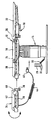
- the drawing shows a side view of an operating table 12 with a Support pillar 14 and a removable from the support column 14 operating table top 16.
- the latter is in the longitudinal direction in three tabletop sections in shape a base portion 18, a Jokkenteils 20 and a foot part 22 divided, wherein the centrally located base portion 18 with the support column 14 is detachably connectable and wherein the back part 20th and the foot part 22 each about a horizontal pivot axis 24 and 26 pivoted at the base portion 18 are stored.
- the operating table 12 also includes a per se known, not shown in the drawing electric drive and a control unit for its control, so that the back and foot parts 20, 22 electric motor can be adjusted.
- the support column 14 in height be changed by electric motor.
- a wired remote control 28 with Input keys 30 are provided, which via a connecting cable 32 with the not shown in the drawing Control unit of the operating table 12 electrically connected is.
- an infrared remote control be provided so that the setting of the operating table 12 even without using a cable can.
- the support column 14 can at the support column 14 provided an additional input keyboard be, with this input keyboard is the highest priority is due, i. the other input elements in shape the wired remote control 28 and a possible infrared remote control are assigned lower priorities, so that the operating table 12 is independent of the setting of, for example, the infrared remote control at any time by pressing the input keyboard the support column in the most advantageous for the patient Location can be brought.
- an inventive add-on module 34 is provided. This is by means of a mechanical quick release device 36 with the back part 20 of the operating table 12 detachably connectable and comprises a holding frame 38, on a known pivoting mechanism 40, which in turn is attached to the Quick release device is held.
- the support frame 38 carries on its top a pad 42 and takes
- Electric drive unit for adjusting the additional module 34 relative to the operating table top 16.
- connection cable 44 is provided at its free End carries a plug 46, which in a corresponding Socket, which is arranged on the support column 14 and connected to the control unit of the operating table 12 is, can be plugged.
- the socket is in the Drawing not shown.
- Alternative or supplementary may also be a socket on the operating table top 16 be provided.
- Operating table tops is the arrangement of a Socket on the operating table top advantageous, because this results in the possibility of the operating table top with coupled additional module of the To remove the support column without being hampered by the connection cable is made.
- the control of the drive unit of the additional module 34 takes place via the control unit of the operating table 12, can the additional module as well as the back and Foot parts 20, 22 of the operating table top 16 by actuation the input keys 30 of the wired remote control 28th be adjusted.
- the control of the additional module 34 in the hierarchy for the operation of the Operating table 12 provided input elements integrated.
Landscapes
- Health & Medical Sciences (AREA)
- Engineering & Computer Science (AREA)
- Biomedical Technology (AREA)
- Life Sciences & Earth Sciences (AREA)
- Animal Behavior & Ethology (AREA)
- General Health & Medical Sciences (AREA)
- Public Health (AREA)
- Veterinary Medicine (AREA)
- Accommodation For Nursing Or Treatment Tables (AREA)
Description
Claims (8)
- Zusatzmodul zur Erweiterung eines verstellbaren, einen Elektroantrieb sowie eine Steuereinheit aufweisenden Operationstisches (12) mit einem Kopplungsglied zur mechanischen Ankopplung an eine Operationstischplatte (16) des Operationstisches (12) und mit einer elektrischen Antriebseinheit zur Verstellung der Orientierung des Zusatzmoduls (34) relativ zur Operationstischplatte (16), wobei die Antriebseinheit über die Steuereinheit des Operationstisches (12) ansteuerbar ist, dadurch gekennzeichnet, daß das Kopplungsglied eine Schnellspannvorrichtung (36) aufweist und mit dem Operationstisch (12) lösbar verbindbar ist.
- Zusatzmodul nach Anspruch 1, dadurch gekennzeichnet, daß das Zusatzmodul als mit der Operationstischplatte (16) lösbar verbindbares Tischplattensegment (34) ausgestaltet ist.
- Zusatzmodul nach Anspruch 1, dadurch gekennzeichnet; daß das Zusatzmodul als mit der Operationstischplatte (16) lösbar verbindbares Halteelement ausgestaltet ist.
- Zusatzmodul nach Anspruch 1, 2 oder 3, dadurch gekennzeichnet, daß das Zusatzmodul ein elektrisches Anschlußkabel (44) zum Anschluß an die Steuereinheit des Operationstisches (12) aufweist.
- Zusatzmodul nach Anspruch 1, 2 oder 3, dadurch gekennzeichnet, daß das Kopplungsglied elektrische Verbindungselemente zum Anschluß der Antriebseinheit an die Steuereinheit des Operationstisches (12) umfaßt.
- Zusatzmodul nach Anspruch 5, dadurch gekennzeichnet, daß die elektrischen Verbindungselemente elektrische Kontaktelemente aufweisen, die beim Ankoppeln des Zusatzmoduls an die Operationstischplatte (16) mit korrespondierenden Kontaktelementen der Operationstischplatte (16) in elektrischen Kontakt treten.
- Zusatzmodul nach einem der voranstehenden Ansprüche, dadurch gekennzeichnet, daß die Antriebseinheit induktiv an die Steuereinheit des Operationstisches (12) anschließbar ist.
- Operationstisch mit einer Operationstischplatte (16) und einer Tragsäule (14) sowie einem Elektroantrieb und einer Steuereinheit zum Verstellen der Operationstischplatte (16) und/oder der Tragsäule (14), wobei der Operationstisch (12) ein elektrisches Verbindungselement umfaßt zum Anschluß mindestens eines mit der Operationstischplatte (16) lösbar verbindbaren Zusatzmoduls (34) nach einem der voranstehenden Ansprüche an die Steuereinheit des Operationstisches (12), dadurch gekennzeichnet, daß der Operationstisch (12) ein mit einer Schnellspannvorrichtung (36) des Zusatzmoduls (34) zusammenwirkendes Element aufweist zur Herstellung der lösbaren Verbindung mit dem Zusatzmodul (34).
Applications Claiming Priority (2)
| Application Number | Priority Date | Filing Date | Title |
|---|---|---|---|
| DE19751329 | 1997-11-19 | ||
| DE19751329.8A DE19751329B4 (de) | 1997-11-19 | 1997-11-19 | Zusatzmodul für einen Operationstisch und Operationstisch mit Zusatzmodul |
Publications (2)
| Publication Number | Publication Date |
|---|---|
| EP0917867A1 EP0917867A1 (de) | 1999-05-26 |
| EP0917867B1 true EP0917867B1 (de) | 2004-05-12 |
Family
ID=7849237
Family Applications (1)
| Application Number | Title | Priority Date | Filing Date |
|---|---|---|---|
| EP98120459A Expired - Lifetime EP0917867B1 (de) | 1997-11-19 | 1998-10-29 | Zusatzmodul für einen Operationstisch |
Country Status (3)
| Country | Link |
|---|---|
| EP (1) | EP0917867B1 (de) |
| DE (2) | DE19751329B4 (de) |
| ES (1) | ES2221109T3 (de) |
Families Citing this family (16)
| Publication number | Priority date | Publication date | Assignee | Title |
|---|---|---|---|---|
| DE19947361A1 (de) * | 1999-10-01 | 2002-01-03 | Siemens Ag | Lagerungsvorrichtungssystem |
| JP2005500083A (ja) | 2001-01-25 | 2005-01-06 | ヒル−ロム サービシーズ,インコーポレイティド | 外科用テーブルのための油圧式アクチュエータ装置 |
| EP1874254B1 (de) * | 2005-04-11 | 2016-05-25 | Allen Medical Systems, Inc. | Akzessorische kontaktklemme mit riegelmechanismen |
| DE102005053753A1 (de) | 2005-11-10 | 2007-05-16 | Maquet Gmbh & Co Kg | Hydraulische Säulenklemmung |
| DE102005054222A1 (de) | 2005-11-14 | 2007-05-16 | Maquet Gmbh & Co Kg | Operationstisch |
| DE102005054223A1 (de) | 2005-11-14 | 2007-05-16 | Maquet Gmbh & Co Kg | Einrichtung zum Verstellen eines Operationstisches |
| DE102005054230A1 (de) | 2005-11-14 | 2007-05-24 | Maquet Gmbh & Co. Kg | Verfahren und Einrichtung zur bidirektionalen IR-Datenübertragung zwischen einem Operationstisch und einem Bediengerät |
| DE102005054175A1 (de) | 2005-11-14 | 2007-05-16 | Maquet Gmbh & Co Kg | Gelenkanordnung zur Verbindung zweier Segmente einer Patientenlagerfläche |
| DE102005054174A1 (de) | 2005-11-14 | 2007-05-16 | Maquet Gmbh & Co Kg | Patientenlagerfläche für einen Operationstisch |
| DE202012009566U1 (de) * | 2012-10-08 | 2014-01-09 | Grass Gmbh | Vorrichtung zur Kontrolle eines Möbels |
| GB2522806B (en) | 2013-06-14 | 2016-01-06 | Eschmann Holdings Ltd | Surgical table and method of operating the same |
| GB2516051B (en) | 2013-07-09 | 2016-06-08 | Eschmann Holdings Ltd | Surgical tables |
| GB2535054B (en) * | 2013-07-12 | 2017-01-11 | Eschmann Holdings Ltd | Tabletop sections for surgical tables |
| US11908574B2 (en) | 2019-07-29 | 2024-02-20 | Trumpf Medizin Systeme Gmbh + Co. Kg | Remote control for a medical apparatus, system of the remote control and the medical apparatus and method for operating the medical apparatus |
| EP3771458B1 (de) * | 2019-07-29 | 2026-05-06 | Baxter Medical Systems GmbH + Co. KG | Fernbedienung für eine medizinische vorrichtung, system aus fernbedienung und medizinischer vorrichtung und verfahren zum betrieb der medizinischen vorrichtung |
| FR3109720A1 (fr) | 2020-05-04 | 2021-11-05 | Steris | Module additionnel motorisé destiné à équiper une table d’opération chirurgicale |
Family Cites Families (5)
| Publication number | Priority date | Publication date | Assignee | Title |
|---|---|---|---|---|
| US3868103A (en) * | 1973-04-24 | 1975-02-25 | Millet Roux & Cie Ltee | Surgical and examination table structure |
| DE4138319A1 (de) * | 1991-11-21 | 1993-05-27 | Stierlen Maquet Ag | Operationstisch mit abnehmbar gehaltener patientenlagerflaeche |
| DE4138317A1 (de) * | 1991-11-21 | 1993-05-27 | Stierlen Maquet Ag | Mechanisch verstellbare haltevorrichtung fuer zusatzgeraete an einem operationstisch |
| DE9218191U1 (de) * | 1992-06-23 | 1993-10-21 | Kaltenbach & Voigt Gmbh & Co, 88400 Biberach | Powermodul |
| DE4423403A1 (de) * | 1994-07-04 | 1996-01-11 | Stierlen Maquet Ag | Verbindungsmodul |
-
1997
- 1997-11-19 DE DE19751329.8A patent/DE19751329B4/de not_active Expired - Lifetime
-
1998
- 1998-10-29 EP EP98120459A patent/EP0917867B1/de not_active Expired - Lifetime
- 1998-10-29 DE DE59811379T patent/DE59811379D1/de not_active Expired - Lifetime
- 1998-10-29 ES ES98120459T patent/ES2221109T3/es not_active Expired - Lifetime
Also Published As
| Publication number | Publication date |
|---|---|
| EP0917867A1 (de) | 1999-05-26 |
| DE19751329A1 (de) | 1999-05-20 |
| ES2221109T3 (es) | 2004-12-16 |
| DE59811379D1 (de) | 2004-06-17 |
| DE19751329B4 (de) | 2015-05-21 |
Similar Documents
| Publication | Publication Date | Title |
|---|---|---|
| EP0917867B1 (de) | Zusatzmodul für einen Operationstisch | |
| DE69112958T2 (de) | Elektrische Kopfstütze, insbesondere für Fahrzeugsitze. | |
| DE2628744C2 (de) | Träger für Schalter und Anzeigen für Fahrzeuge | |
| EP0917868B1 (de) | Steuereinheit zur Ansteuerung einer Operationstischplatte | |
| EP1785119B1 (de) | Operationstisch | |
| EP0362608B2 (de) | Lichtwarnvorrichtung | |
| DE19781782B4 (de) | Kopfstütze für Sitze | |
| EP1288763A2 (de) | Vorrichtung zum Steuern eines landwirtschaftlichen Fahrzeugs | |
| DE3609690A1 (de) | Sitzeinstellvorrichtung fuer einen mit einer antriebsvorrichtung verstellbaren sitz | |
| DE19910774A1 (de) | Fahrzeug-Frischluftdüseneinrichtung | |
| DE102019206584B3 (de) | Kraftfahrzeug | |
| DE202016103388U1 (de) | Luftausströmer | |
| DE7920475U1 (de) | Hoehenverstellbare kopfstuetze eines kraftfahrzeugsitzes | |
| DE102009001324A1 (de) | Lenksäulenhalterung und damit ausgestattetes Lenksystem | |
| EP1265577A1 (de) | Medizinischer oder dentalmedizinischer behandlungsstuhl | |
| DE19631454C2 (de) | Fahrzeugsitz mit einer Sitzplatte und einer Rückenlehne | |
| EP3736378B1 (de) | Einbaubohle mit schnellkupplung für aussenbedienstand | |
| DE102016214611A1 (de) | Pedalanordnung für ein Kraftfahrzeug | |
| DE3211478A1 (de) | Einstellvorrichtung fuer rueckspiegel eines nutzfahrzeugs | |
| DE602005002636T2 (de) | Aussenrückblickspiegel für Kraftfahrzeuge mit Formgedächtnisbetätigungsorgan | |
| DE2932344A1 (de) | Vorrichtung zur verstellung einer kopfstuetze | |
| DE102009036259A1 (de) | Außenrückspiegel | |
| EP3748224B1 (de) | Lampe | |
| DE19907134C1 (de) | Bediengerät, insbesondere für ein Kraftfahrzeug, mit einem abschwenkbaren Bedienfeld | |
| DE102017105920A1 (de) | Verstellvorrichtung für einen Fahrzeugsitz |
Legal Events
| Date | Code | Title | Description |
|---|---|---|---|
| PUAI | Public reference made under article 153(3) epc to a published international application that has entered the european phase |
Free format text: ORIGINAL CODE: 0009012 |
|
| AK | Designated contracting states |
Kind code of ref document: A1 Designated state(s): DE ES FR GB IT |
|
| AX | Request for extension of the european patent |
Free format text: AL;LT;LV;MK;RO;SI |
|
| 17P | Request for examination filed |
Effective date: 19990703 |
|
| AKX | Designation fees paid |
Free format text: DE ES FR GB IT |
|
| RAP1 | Party data changed (applicant data changed or rights of an application transferred) |
Owner name: TRUMPF MEDIZIN SYSTEME GMBH. |
|
| 17Q | First examination report despatched |
Effective date: 20020916 |
|
| GRAP | Despatch of communication of intention to grant a patent |
Free format text: ORIGINAL CODE: EPIDOSNIGR1 |
|
| GRAS | Grant fee paid |
Free format text: ORIGINAL CODE: EPIDOSNIGR3 |
|
| GRAA | (expected) grant |
Free format text: ORIGINAL CODE: 0009210 |
|
| AK | Designated contracting states |
Kind code of ref document: B1 Designated state(s): DE ES FR GB IT |
|
| REG | Reference to a national code |
Ref country code: GB Ref legal event code: FG4D Free format text: NOT ENGLISH |
|
| GBT | Gb: translation of ep patent filed (gb section 77(6)(a)/1977) |
Effective date: 20040512 |
|
| REF | Corresponds to: |
Ref document number: 59811379 Country of ref document: DE Date of ref document: 20040617 Kind code of ref document: P |
|
| REG | Reference to a national code |
Ref country code: ES Ref legal event code: FG2A Ref document number: 2221109 Country of ref document: ES Kind code of ref document: T3 |
|
| ET | Fr: translation filed | ||
| PLAQ | Examination of admissibility of opposition: information related to despatch of communication + time limit deleted |
Free format text: ORIGINAL CODE: EPIDOSDOPE2 |
|
| PLBQ | Unpublished change to opponent data |
Free format text: ORIGINAL CODE: EPIDOS OPPO |
|
| PLAQ | Examination of admissibility of opposition: information related to despatch of communication + time limit deleted |
Free format text: ORIGINAL CODE: EPIDOSDOPE2 |
|
| PLAR | Examination of admissibility of opposition: information related to receipt of reply deleted |
Free format text: ORIGINAL CODE: EPIDOSDOPE4 |
|
| PLBQ | Unpublished change to opponent data |
Free format text: ORIGINAL CODE: EPIDOS OPPO |
|
| PLBI | Opposition filed |
Free format text: ORIGINAL CODE: 0009260 |
|
| PLAX | Notice of opposition and request to file observation + time limit sent |
Free format text: ORIGINAL CODE: EPIDOSNOBS2 |
|
| 26 | Opposition filed |
Opponent name: MAQUET GMBH & CO. KG Effective date: 20050211 |
|
| PLBB | Reply of patent proprietor to notice(s) of opposition received |
Free format text: ORIGINAL CODE: EPIDOSNOBS3 |
|
| PLCK | Communication despatched that opposition was rejected |
Free format text: ORIGINAL CODE: EPIDOSNREJ1 |
|
| APBP | Date of receipt of notice of appeal recorded |
Free format text: ORIGINAL CODE: EPIDOSNNOA2O |
|
| APAH | Appeal reference modified |
Free format text: ORIGINAL CODE: EPIDOSCREFNO |
|
| APBQ | Date of receipt of statement of grounds of appeal recorded |
Free format text: ORIGINAL CODE: EPIDOSNNOA3O |
|
| RAP2 | Party data changed (patent owner data changed or rights of a patent transferred) |
Owner name: TRUMPF MEDIZIN SYSTEME GMBH. |
|
| APBU | Appeal procedure closed |
Free format text: ORIGINAL CODE: EPIDOSNNOA9O |
|
| PLBN | Opposition rejected |
Free format text: ORIGINAL CODE: 0009273 |
|
| STAA | Information on the status of an ep patent application or granted ep patent |
Free format text: STATUS: OPPOSITION REJECTED |
|
| 27O | Opposition rejected |
Effective date: 20101011 |
|
| REG | Reference to a national code |
Ref country code: FR Ref legal event code: PLFP Year of fee payment: 19 |
|
| PGFP | Annual fee paid to national office [announced via postgrant information from national office to epo] |
Ref country code: FR Payment date: 20160919 Year of fee payment: 19 |
|
| PGFP | Annual fee paid to national office [announced via postgrant information from national office to epo] |
Ref country code: ES Payment date: 20160913 Year of fee payment: 19 |
|
| PGFP | Annual fee paid to national office [announced via postgrant information from national office to epo] |
Ref country code: GB Payment date: 20161026 Year of fee payment: 19 |
|
| PGFP | Annual fee paid to national office [announced via postgrant information from national office to epo] |
Ref country code: IT Payment date: 20161024 Year of fee payment: 19 |
|
| PGFP | Annual fee paid to national office [announced via postgrant information from national office to epo] |
Ref country code: DE Payment date: 20170920 Year of fee payment: 20 |
|
| GBPC | Gb: european patent ceased through non-payment of renewal fee |
Effective date: 20171029 |
|
| REG | Reference to a national code |
Ref country code: FR Ref legal event code: ST Effective date: 20180629 |
|
| PG25 | Lapsed in a contracting state [announced via postgrant information from national office to epo] |
Ref country code: GB Free format text: LAPSE BECAUSE OF NON-PAYMENT OF DUE FEES Effective date: 20171029 |
|
| PG25 | Lapsed in a contracting state [announced via postgrant information from national office to epo] |
Ref country code: FR Free format text: LAPSE BECAUSE OF NON-PAYMENT OF DUE FEES Effective date: 20171031 |
|
| REG | Reference to a national code |
Ref country code: DE Ref legal event code: R071 Ref document number: 59811379 Country of ref document: DE |
|
| PG25 | Lapsed in a contracting state [announced via postgrant information from national office to epo] |
Ref country code: IT Free format text: LAPSE BECAUSE OF NON-PAYMENT OF DUE FEES Effective date: 20171029 |
|
| REG | Reference to a national code |
Ref country code: ES Ref legal event code: FD2A Effective date: 20181221 |
|
| PG25 | Lapsed in a contracting state [announced via postgrant information from national office to epo] |
Ref country code: ES Free format text: LAPSE BECAUSE OF NON-PAYMENT OF DUE FEES Effective date: 20171030 |