EP0918403A2 - Récepteurs en diversité d'espace - Google Patents
Récepteurs en diversité d'espace Download PDFInfo
- Publication number
- EP0918403A2 EP0918403A2 EP99102025A EP99102025A EP0918403A2 EP 0918403 A2 EP0918403 A2 EP 0918403A2 EP 99102025 A EP99102025 A EP 99102025A EP 99102025 A EP99102025 A EP 99102025A EP 0918403 A2 EP0918403 A2 EP 0918403A2
- Authority
- EP
- European Patent Office
- Prior art keywords
- signal
- processing circuit
- antenna
- signals
- signal processing
- Prior art date
- Legal status (The legal status is an assumption and is not a legal conclusion. Google has not performed a legal analysis and makes no representation as to the accuracy of the status listed.)
- Withdrawn
Links
Images

Classifications
-
- H—ELECTRICITY
- H04—ELECTRIC COMMUNICATION TECHNIQUE
- H04B—TRANSMISSION
- H04B7/00—Radio transmission systems, i.e. using radiation field
- H04B7/02—Diversity systems; Multi-antenna system, i.e. transmission or reception using multiple antennas
- H04B7/04—Diversity systems; Multi-antenna system, i.e. transmission or reception using multiple antennas using two or more spaced independent antennas
- H04B7/08—Diversity systems; Multi-antenna system, i.e. transmission or reception using multiple antennas using two or more spaced independent antennas at the receiving station
- H04B7/0802—Diversity systems; Multi-antenna system, i.e. transmission or reception using multiple antennas using two or more spaced independent antennas at the receiving station using antenna selection
- H04B7/0805—Diversity systems; Multi-antenna system, i.e. transmission or reception using multiple antennas using two or more spaced independent antennas at the receiving station using antenna selection with single receiver and antenna switching
- H04B7/0808—Diversity systems; Multi-antenna system, i.e. transmission or reception using multiple antennas using two or more spaced independent antennas at the receiving station using antenna selection with single receiver and antenna switching comparing all antennas before reception
- H04B7/0811—Diversity systems; Multi-antenna system, i.e. transmission or reception using multiple antennas using two or more spaced independent antennas at the receiving station using antenna selection with single receiver and antenna switching comparing all antennas before reception during preamble or gap period
-
- H—ELECTRICITY
- H04—ELECTRIC COMMUNICATION TECHNIQUE
- H04B—TRANSMISSION
- H04B7/00—Radio transmission systems, i.e. using radiation field
- H04B7/02—Diversity systems; Multi-antenna system, i.e. transmission or reception using multiple antennas
- H04B7/04—Diversity systems; Multi-antenna system, i.e. transmission or reception using multiple antennas using two or more spaced independent antennas
- H04B7/08—Diversity systems; Multi-antenna system, i.e. transmission or reception using multiple antennas using two or more spaced independent antennas at the receiving station
- H04B7/0802—Diversity systems; Multi-antenna system, i.e. transmission or reception using multiple antennas using two or more spaced independent antennas at the receiving station using antenna selection
- H04B7/0805—Diversity systems; Multi-antenna system, i.e. transmission or reception using multiple antennas using two or more spaced independent antennas at the receiving station using antenna selection with single receiver and antenna switching
- H04B7/0814—Diversity systems; Multi-antenna system, i.e. transmission or reception using multiple antennas using two or more spaced independent antennas at the receiving station using antenna selection with single receiver and antenna switching based on current reception conditions, e.g. switching to different antenna when signal level is below threshold
-
- H—ELECTRICITY
- H04—ELECTRIC COMMUNICATION TECHNIQUE
- H04B—TRANSMISSION
- H04B7/00—Radio transmission systems, i.e. using radiation field
- H04B7/02—Diversity systems; Multi-antenna system, i.e. transmission or reception using multiple antennas
- H04B7/04—Diversity systems; Multi-antenna system, i.e. transmission or reception using multiple antennas using two or more spaced independent antennas
- H04B7/08—Diversity systems; Multi-antenna system, i.e. transmission or reception using multiple antennas using two or more spaced independent antennas at the receiving station
- H04B7/0802—Diversity systems; Multi-antenna system, i.e. transmission or reception using multiple antennas using two or more spaced independent antennas at the receiving station using antenna selection
- H04B7/0817—Diversity systems; Multi-antenna system, i.e. transmission or reception using multiple antennas using two or more spaced independent antennas at the receiving station using antenna selection with multiple receivers and antenna path selection
Definitions
- the present invention relates generally to space diversity receivers, and more particularly, to an improved space diversity receiver which has at least two antennas spaced from each other and is operative to select the best one of signals received respectively by the antennas to obtain reproduced video and/or audio signals therefrom.
- the space diversity receiver used in the automobile is accompanied with, for example, four antenna connectors mounted on middle and rear parts of each of left and right sides of a cabin portion each to be coupled with an antenna.
- output signals of a signal processing circuit block produced respectively based on signals obtained from the antenna connectors are compared in quality with one another to select one of the antenna connectors through which a signal giving rise to the best output signal of the signal processing circuit block is introduced, and then during a period successive to the specific period, the signal introduced through a selected antenna connector is supplied to the signal processing circuit block.
- the signal processing circuit block produces a received signal output based on the signal introduced through the selected antenna connector, from which reproduced video and audio signals are produced.
- the signal obtained from the antenna connector constitutes an antenna output signal when an antenna is connected with the antenna connector.
- the signal obtained from the antenna connector with which any antenna is not connected does not constitute the antenna output signal.
- the output signals of the signal processing circuit block is derived to be interconnected with a discontinuous portion between each successive two so as to produce a received signal output. Since the signal sampling operation is performed in, for example, the vertical blanking period of the television broadcast signal to be received, no substantial trouble or problem is brought about on a picture produced in accordance with the reproduced video signal which is obtained based on the received signal output derived from the signal processing circuit block even if the received signal output derived from the processing circuit block contains the discontinuous portions therein.
- the signal sampling operation for selecting the antenna connector through which the signal giving rise to the best output signal of the signal processing circuit block is performed minimum times under the necessity in order to suppress the harsh noise contained in the sound produced in accordance with the reproduced audio signal.
- the signal processing circuit block cannot produce a correct output signal thereof during a short period in which the signal obtained from the antenna connector with which the antenna is not provided is supplied thereto and therefore the received signal output is intermittently derived form the signal processing circuit block to include lacking portions.
- a sound produced in accordance with the reproduced audio signal obtained based on such a received signal output as to include the lacking portions contains also harsh noise resulting from the lacking portions of the received signal output.
- Another object of the present invention is to provide an improved space diversity receiver for receiving broadcast signals, in which a plurality of antenna connectors are provided so that a signal sampling operation wherein signals obtained respectively from the antenna connectors are selectively sampled to be successively supplied to a signal processing circuit block is performed and output signals of the signal processing circuit block produced respectively based on the sampled signals are compared in quality with one another to select one of the antenna connectors through which a signal giving rise to the best output signal of the signal processing circuit block is introduced during a specific period, and then during a period successive to the specific period, the signal introduced through a selected antenna connector is supplied continuously to the signal processing circuit block to produce a received signal output, and which can effectively reduce harsh noise occurring in a sound reproduced based on the received signal output derived from the signal processing circuit block as a result of the signal sampling operation.
- a further object of the present invention is to provide an improved space diversity receiver for receiving broadcast signals, in which a plurality of antenna connectors are provided so that a signal sampling operation wherein signals obtained respectively from the antenna connectors are selectively sampled to be successively supplied to a signal processing circuit block is performed and output signals of the signal processing circuit block produced respectively based on the sampled signals are compared in quality with one another to select one of the antenna connectors through which a signal giving rise to the best output signal of the signal processing circuit block is introduced during a specific period, and then during a period successive to the specific period, the signal introduced through a selected antenna connector is supplied continuously to the signal processing circuit block to produce a received signal output, and which can effectively reduce harsh noise occurring in a sound reproduced based on the received signal output derived from the signal processing circuit block in response to lacking portions of the received signal output resulting from the signal sampling operation.
- a further object of the present invention is to provide an improved space diversity receiver for receiving broadcast signals, in which a plurality of antenna connectors are provided so that a signal sampling operation wherein signals obtained respectively from the antenna connectors are selectively sampled to be successively supplied to a signal processing circuit block is performed and output signals of the signal processing circuit block produced respectively based on the sampled signals are compared in quality with one another to select one of the antenna connectors through which a signal giving rise to the best output signal of the signal processing circuit block is introduced during a specific period, and then during a period successive to the specific period, the signal introduced through a selected antenna connector is supplied continuously to the signal processing circuit block to produce a received signal output, and which can effectively reduce harsh noise occurring in a sound reproduced based on the received signal output derived from the signal processing circuit block in response to discontinuous portions of the received signal output resulting from the signal sampling operation.
- a still further object of the present invention is to provide an improved space diversity receiver for receiving broadcast signals, in which a plurality of antenna connectors are provided so that a signal sampling operation wherein signals obtained respectively from the antenna connectors are selectively sampled to be successively supplied to a signal processing circuit block is performed and output signals of the signal processing circuit block produced respectively based on the sampled signals are compared in quality with one another to select one of the antenna connectors through which a signal giving rise to the best output signal of the signal processing circuit block is introduced during a specific period, and then during a period successive to the specific period, the signal introduced through a selected antenna connector is supplied continuously to the signal processing circuit block to produce a received signal output, and which can effectively reduce harsh noise occurring in a sound reproduced based on the received signal output derived from the signal processing circuit block in response to lacking portions of the received signal output resulting from the signal sampling operation.
- a space diversity receiver comprising a plurality of antenna connectors, with each of which an antenna is to be connected, a signal selecting portion for selecting one of signals obtained respectively from the antenna connectors, a signal processing circuit block operative to produce an output signal based on a signal selected by the signal selector, a signal sampling control portion operative to cause the signal selecting portion to perform a signal sampling operation through which the signals obtained respectively from the antenna connectors are selectively sampled for every predetermined short period to be supplied to the signal processing circuit block during a specific period, an antenna connector selecting portion operative to compare in quality the output signals of the signal processing circuit block obtained successively based on signals sampled through the signal sampling operation performed by the signal selecting portion with one another in order to select one of the antenna connectors through which a signal giving rise to the best output signal of the signal processing circuit block is introduced during the specific period, and a signal selecting control portion operative to cause the signal selecting portion to select the signal introduced through the antenna connector selected by the antenna connector selecting portion during a period
- a space diversity receiver comprising a plurality of antenna connectors, with each of which an antenna is to be connected, a signal selecting portion for selecting one of signals obtained from the antenna connectors, a signal processing circuit block operative to produce an output signal based on a signal selected by the signal selector, a signal sampling control portion operative to cause the signal selecting portion to perform a signal sampling operation through which the signals obtained respectively from the antenna connectors are selectively sampled for every predetermined short period to be supplied to the signal processing circuit block during a specific period, an antenna connector selecting portion operative to compare in quality the output signals of the signal processing circuit block obtained successively based on signals sampled through the signal sampling operation performed by the signal selecting portion with one another in order to select one of the antenna connectors through which a signal giving rise to the best output signal of the signal processing circuit block is introduced during the specific period, a signal selecting control portion operative to cause the signal selecting portion to select the signal introduced through the antenna connector selected by the antenna connector selecting portion during a period
- the space diversity receiver thus constituted in accordance with one aspect of the present invention, under a condition in which the signal sampling operation is performed by the signal selecting portion and the output signals of the signal processing circuit block obtained based on the signals sampled successively through the signal sampling operation are compared with one another by the antenna connector selecting portion in order to select the antenna connector through which the signal giving rise to the best output signal of the signal processing circuit block is introduced during the specific period, the frequency of signal sampling operations in the signal selecting portion is reduced in response to increase in stability of the signal selected to be supplied to the signal processing circuit block during the period successive to the specific period and then the signal sampling operation is stopped when the signal selected to be supplied to the signal processing circuit block during the period successive to the specific period is sufficiently stabilized.
- the signal sampling operation is performed minimum times under the necessity, so that harsh noise occurring in a sound reproduced based on a received signal output derived from the signal processing circuit block in response to discontinuous portions of the received signal output resulting from the signal sampling operation is effectively reduced.
- the space diversity receiver constituted as described above in accordance with another aspect of the present invention, under a condition in which the signal sampling operation is performed by the signal selecting portion and the output signals of the signal processing circuit block obtained based on the signals sampled successively through the signal sampling operation are compared with one another by the antenna connector selecting portion in order to select the antenna connector through which the signal giving rise to the best output signal of the signal processing circuit block is introduced during the specific period, the antenna connector with which the antenna is not connected is detected and the signal sampling operation is caused not to sample the signal obtained from the detected antenna connector.
- a received signal output derived from the signal processing circuit block during the specific period does not contain a lacking portion thereof, so that harsh noise occurring in a sound reproduced based on the received signal output derived from the signal processing circuit block in response to lacking portions of the received signal output resulting from the signal sampling operation is effectively reduced.
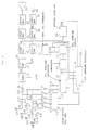
- Fig. 1 shows a first embodiment of space diversity receiver according to the present invention.
- the embodiment shown in Fig. 1 constitutes a space diversity receiver for use in an automobile to receive a television broadcast signal.
- the space diversity receiver of Fig. 1 includes four antenna connectors 11A, 11B, 11C and 11D mounted respectively on middle and rear portions of each of left and right outer sides of a cabin of an automobile, and antennas 12A, 12B, 12C and 12D are connected with the antenna connectors 11A to 11D, respectively.
- Antenna connector signals SA, SB, SC and SD which are obtained through the antenna connectors 11A to 11D, respectively, when the television broadcast signal is received by each of the antennas 12A to 12D, are supplied through a capacitor 14A to a switching diode 15A, through a capacitor 14B to a switching diode 15B, through a capacitor 14C to a switching diode 15C and through a capacitor 14D to a switching diode 15D, respectively.
- the switching diodes 15A to 15D are controlled as explained later in such a manner that only one of the switching diodes 15A to 15D is put in the ON state to allow a signal to pass therethrough and therefore one of the antenna connector signals SA, SB, SC and SD is supplied through one of the switching diodes 15A to 15D and a capacitor 16 to a tuner 31 which constitutes a part of signal processing circuit block 30.
- the antenna connector signal SA, SB, SC or SD is amplified and subjected to frequency conversion. Then, a video intermediate frequency signal SVI is obtained based on the antenna connector signal SA, SB, SC or SD from the tuner 31 and supplied to an intermediate frequency amplifier 32.
- the video intermediate frequency signal SVI amplified by the intermediate frequency amplifier 32 is then supplied to a video detector 33. In the video detector 33, the video intermediate frequency signal SVI is demodulated to produce a video signal VD.
- the video signal VD derived from the video detector 33 is amplified by a video amplifier 34 and then further amplified by an output amplifier 35 to be supplied to a cathode ray tube 36, so that a reproduced picture is obtained based on the video signal VD on a display screen of the cathode ray tube 36.
- An audio intermediate frequency signal SAI separated from the video intermediate frequency signal SVI is also obtained from the intermediate frequency amplifier 32 to be supplied to an audio intermediate frequency amplifier 37.
- the audio intermediate frequency signal SAI amplified by the audio intermediate frequency amplifier 37 is supplied to an audio detector 38.
- the audio intermediate frequency signal SAI is demodulated to produce an audio signal AU.
- the audio signal AU derived from the audio detector 38 is amplified by an audio amplifier 39 to be supplied to a speaker 40, so that a reproduced sound is obtained based on the audio signal AU from the speaker 40.
- a signal to noise ratio (S/N ratio) of the antenna connector signal SA, SB, SC or SD is detected and a detection output signal SSN produced thereby is sent out of the tuner 31.
- the video signal VD derived from the video detector 33 is also supplied to each of a synchronous signal separator 41, a signal sampling circuit 42 and a pedestal level detector 60.
- a synchronous signal separator 41 a vertical synchronous signal SV and a horizontal synchronous signal SH are separated from the video signal VD, and in the pedestal level defector 60, a pedestal level of the video signal VD is detected to produce a detection output signal SPL which varies in response to variations in the pedestal level of the video signal VD.
- the detection output signal SSN derived from the tuner 31, the vertical and horizontal synchronous signals SV and SH obtained from the synchronous signal separator 41, and the detection output signal SPL obtained from the pedestal level detector 60 are supplied to a signal sampling controller 46.
- the signal sampling controller 46 is operative to detect a predetermined specific period in a vertical blanking period of the video signal VD, such a period as corresponding to an equalizing pulse period successive to the vertical synchronous signal SV, on the strength of the vertical and horizontal synchronous signals SV and SH and to supply a diode driving signal generator 47 with a control signal SS during the specific period detected in every vertical blanking period of the video signal VD or during the specific period detected in every predetermined number of vertical blanking periods of the video signal VD.
- the diode driving signal generator 47 includes four output terminals connected through choke coils 48, 49, 50 and 51 with anodes of the switching diodes 15A to 15D, respectively. Cathodes of the switching diode 15A to 15D are connected in common and grounded through a choke coil 52 and a parallel connection of a resistor 53 and a capacitor 54.
- the diode driving signal generator 47 is operative to supply through the output terminals thereof respectively the anodes of the switching diodes 15A to 15D with driving signal C1, C2, C3 and C4 successively for every predetermined short period, such as every period of several microseconds, in response to the control signal SS supplied from the signal sampling controller 46 during the specific period.
- the switching diodes 15A to 15D are put in the ON state respectively by the driving signals C1 to C4 supplied to the cathodes of the switching diodes 15A to 15D.
- the switching diodes 15A to 15D are successively put in the ON state for every predetermined short period so that a signal sampling operation by which the antenna connector signals SA, SB, SC and SD are successively sampled for every predetermined short period to be supplied to the tuner 31 is carried out.
- the switching diodes 15A to 15D and the diode driving signal generator 47 constitute an antenna connector signal selecting portion, and during the specific period, such as the period corresponding to the equalizing pulse period next to the vertical synchronous signal, in every vertical blanking period or every predetermined number of vertical blanking periods of the video signal VD, the video signal VD based on the antenna connector signal SA, video signal VD based on the antenna connector signal SB, video signal VD based on the antenna connector signal SC and video signal VD based on the antenna connector signal SD are successively obtained for every predetermined short period from the video detector 33.
- the video signals VD thus obtained based on the antenna connector signals SA, SB, SC and SD, respectively, are supplied to the signal sampling circuit 42 to which the vertical and horizontal synchronous signals SV and SH derived from the synchronous signal separator 41 and the control signal SS derived from the signal sampling controller 46 are also supplied.
- the signal sampling circuit 42 is operative to pick out successively each of the video signals VD obtained based on the antenna connector signals SA, SB, SC and SD, respectively, to be supplied a comparator 43 in synchronism with the control signal SS derived from the signal sampling controller 46.
- the comparator 43 is operative to hold each of the video signals VD obtained based on the antenna connector signals SA, SB, SC and SD, respectively, and selected successively by the signal sampling circuit 42 and to compare in quality the video signals VD obtained based on the antenna connector signals SA, SB, SC and SD with one another so as to select the best one of the video signals VD obtained based on the antenna connector signals SA, SB, SC and SD, respectively.
- a comparison output signal SR representing the best video signal VD selected by the comparator 43 is obtained from the comparator 43 to be supplied to a signal selecting controller 44.
- the signal sampling circuit 42 and the comparator 43 constitute a signal selector for selecting one of the antenna connector signals SA, SB, SC and SD which gives rise to the best one of the video signals VD obtained based on the antenna connector signals SA, SB, SC and SD, respectively, during the specific period detected by the signal sampling controller 46.
- the signal selecting controller 44 to which the vertical and horizontal synchronous signals SV and SH derived from the synchronous signal separator 41 are supplied, is operative to supply the diode driving signal generator 47 with a control signal SZ which has different aspects respectively in the case where the comparison output signal SR represents the video signal VD obtained based on the antenna connector signal SA, in the case where the comparison output signal SR represents the video signal VD obtained based on the antenna connector signal SB, in the case where the comparison output signal SR represents the video signal VD obtained based on the antenna connector signal SC, and in the case where the comparison output signal SR represents the video signal VD obtained based on the antenna connector signal SD, during a period successive to the specific period in the vertical blanking period of the video signal VD.
- the diode driving signal generator 47 does not supply each of the switching diodes 15B to 15D with any driving signal but supplies the switching diode 15A with the driving signal C1 so as to cause only the switching diode 15A to be in the ON state when the control signal SZ from the signal selecting controller 44 corresponds to the comparison output signal SR representing the video signal VD obtained based on the antenna connector signal SA; does not supply each of the switching diodes 15A, 15C and 15D with any driving signal but supplies the switching diode 15B with the driving signal C2 so as to cause only the switching diode 15B to be in the ON state when the control signal SZ from the signal selecting controller 44 corresponds to the comparison output signal SR representing the video signal VD obtained based on the antenna connector signal SB; does not supply each of the switching diodes 15A, 15B and 15D with any driving signal but supplies the switching diode 15C with the driving signal C3 so as to cause only the switching diode 15C to be in the ON state when the control signal SZ from the signal selecting
- one of the switching diodes 15A to 15D is caused to be in the ON state in such a manner as mentioned above so that one of the antenna connector signals SA, SB, SC and SD is supplied to the tuner 31 and thereby the best one of the video signals VD obtained based on the antenna connector signals SA, SB, SC and SD, respectively, is derived from the video detector.
- the comparison output signal SR is also supplied to the signal sampling controller 46.
- the signal sampling controller 46 determines the frequency of supplies of the control signal SS based on the comparison output signal SR, the detection output signal SSN, the detection output signal SPL and the vertical synchronous signal SV.
- the frequency of supplies of the control signal SS in the signal sampling controller 46 fixes the frequency of signal sampling operations in the antenna output signal selecting portion comprising the switching diodes 15A to 15D and the diode driving signal generator 47.
- the frequency of signal sampling operations in the antenna output signal selecting portion is classified into, for example, six sampling modes M1, M2, M3, M4, M5 and M6 in accordance with the condition of one of the antenna connector signals SA, SB, SC and SD selected to give rise to the best video signal VD, which can be detected on the strength of the comparison output signal SR derived from the comparator 43 and the details of each of the sampling modes M1 to M6 are shown in Table - I mentioned below.
- SMD represents a sampling mode
- Freq. of Sampl. represents the frequency of signal sampling operations
- V-Period represents a vertical period or field period of the video signal VD
- Nx represents a difference between the number of selection times per unit period of one of the antenna connector signals SA, SB, SC and SD which is selected the most frequently to give ride to the best video signal VD and the number of selection times per unit period of another of the antenna connector signals SA, SB, SC and SD is selected the second most frequently to give rise to the best video signal VD.
- the frequency of signal sampling operations in the antenna output signal selecting portion changes from the sampling mode M1 toward the sampling mode M6 to be reduced in response to reduction in the value of Nx. Since the value of Nx reduces in response to increase in stability of the antenna connector signal SA, SB, SC or SD which is selected by the antenna connector signal selecting portion so as to be supplied to the signal processing circuit block 30 during the period successive to the specific period in the vertical blanking period of the video signal VD, the frequency of signal sampling operations in the antenna connector signal selecting portion is reduced in response to increase in stability of the antenna connector signal SA, SB, SC or SD which is selected by the antenna connector signal selecting portion so as to be supplied to the signal processing circuit block 30 during the period successive to the specific period in the vertical blanking period of the video signal VD.
- the sampling mode M6 is set up so that the signal sampling operation in the antenna connector signal selecting portion is stopped.
- the signal sampling controller 46 detects the S/N ratio of the antenna connector signal SA, SB, SC or SD which is selected to be supplied to the tuner 31 during the period successive to the specific period in the vertical blanking period of the video signal VD at predetermined intervals based on the detection output signal SSN derived from the tuner 31 and supplied the diode driving signal generator 47 with the control signal SS in such a manner as to change the sampling mode M6 into the sampling mode M5 when reduced S/N ratio is detected continuously predetermined times, for example, twenty times.
- the signal sampling controller 46 detects the pedestal level of the video signal VD obtained from the video detector 33 at predetermined intervals based on the detection output signal SPL derived from the pedestal level detector 60 and supplied the diode driving signal generator 47 with the control signal SS in such a manner as to change the sampling mode M6 into the sampling mode M5 when the pedestal level lower than a relatively low reference level is detected continuously predetermined times, for example, twenty times.
- the sampling mode M6 is changed into the sampling mode M5 so that the signal sampling operation in the antenna connector signal sampling portion is resumed when the S/N ratio of the antenna connector signal SA, SB, SC or SD selected to be supplied to the tuner 31 during the period successive to the specific period in the vertical blanking period of the video signal VD has deteriorated or the pedestal level of the video signal VD obtained from the video detector 33 has lowered beyond the reference level.
- the signal sampling controller 46 supplies the diode driving signal generator 47 with the control signal SS in such a manner as to bring down the sampling mode by one rank, such as to the sampling mode M4 from the sampling mode M5 or to the sampling mode M3 from the sampling mode M4, so as to increase the frequency of signal sampling operations in the antenna connector signal selecting portion, when it is confirmed that the vertical synchronous signal SV is in such a condition as to fail to be derived from the synchronous signal separator 41 repeatedly over a predetermined number of times.
- the signal sampling operation is performed minimum times under the necessity so that harsh noise resulting from the signal sampling operation to be contained in the reproduced sound which is obtained from the speaker 40 in accordance with the audio signal AU is effectively suppressed.
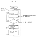
- the signal sampling controller 46 employed in the embodiment shown in Fig. 1 to operate as aforementioned is composed of, for example, a microcomputor and examples of control programs carried out by such a microcomputor for controlling the signal sampling operation in the antenna connector signal selecting portion are shown by flow charts of Figs. 2 and 3.
- step 71 the sampling mode (SMD) M1 as shown in Table - I is set up. Then, in step 72, it is checked whether the vertical synchronous signal SV fails to be supplied to the signal sampling controller 46 from the synchronous signal separator 41 or not. When the vertical synchronous signal SV fails to be supplied to the signal sampling controller 46, it is further checked whether a number Nd of failing times of the vertical synchronous signal SV is more than a maximum permissible number NN or not, in step 73. If the number Nd of failing tomes is larger than the maximum permissible number NN, it is checked whether the sampling mode M1 has been set or not, in step 74.
- SMD sampling mode
- step 75 the sampling mode set on that occasion is brought down by one rank, in step 75, and the process advances to step 76.
- the process advances to the step 76 directly from the step 74.
- step 76 it is checked whether counted value CA is zero or not. If the counted value CA is not zero, the counted value CA is set to be zero in step 77, and the process advances to step 78. If the counted value CA is zero, the process advances to the process 78 directly from the step 76. In the step 78, it is checked whether counted value CB is zero or not. If the counted value CB is not zero, the counted value CB is set to be zero in step 79 and the process advances to step 80. If the counted value CB is zero, the process advances to the step 80 directly from the step 78.
- step 80 the control signal SS corresponding to the sampling mode set on that occasion is supplied to the diode driving signal generator 47, and then the process returns to the step 72.
- the difference Nx between the number of selection times N1 of one of the antenna connector signals SA, SB, SC and SD which is selected the most frequently to give ride to the best video signal VD and the number of selection times N2 of another of the antenna connector signals SA, SB, SC and SD is selected the second most frequently to give rise to the best video signal VD is calculated, in step 81.
- the number of selection times N1 and the number of selection times N2 are obtained from a table of antenna connector signal selecting data which is prepared to be renewed base on the comparison output signal SR derived from the comparator 43 through another control program explained later. Then, in step 82, it is checked whether the value of the difference Nx is larger than or equal to a value NL of the lower limit of the difference Nx which corresponds to the sampling mode set on that occasion or not. If the value of the difference Nx is smaller than the value NL of the lower limit of the difference Nx, the process advances to the step 74.
- step 83 If the value of the difference Nx is larger than or equal to the value NL of the lower limit of the difference Nx, it is checked whether the value of the difference Nx is smaller than or equal to a value NH of the upper limit of the difference Nx which corresponds to the sampling mode set on that occasion or not, in step 83. If the value of the difference Nx is smaller than or equal to the value NH of the upper limit of the difference Nx, the process advances to the step 76.
- step 84 If the value of the difference Nx is larger than the value NH of the upper limit of the difference Nx, it is checked whether the sampling mode M6 has been set or not, in step 84.
- the sampling mode M6 has not been set, the sampling mode set on that occasion is raised by one rank, in step 85, and the process advances to the step 80.
- the control signal SS corresponding to the sampling mode set on that occasion is supplied to the diode driving signal generator 47, and the process returns to the step 72.
- step 84 it is checked based on the detection output signal SSN derived from the tuner 31 whether the S/N ratio of the antenna connector signal SA, SB, SC or SD selected to be supplied to the tuner 31 during the period successive to the specific period in the vertical blanking period of the video signal VD is reduced or not, in step 86. If the S/N ratio of the antenna connector signal SA, SB, SC or SD selected to be supplied to the tuner 31 is not reduced, it is checked whether the counted value CA is zero or not, in step 87. If the counted value CA is not zero, the counted value CA is set to be zero in step 88 and the process advances to step 93. If the counted value CA is zero, the process advances to the step 93 directly from the step 87.
- the counted value CA is increased by "1" in step 89 and then it is checked whether the counted value CA is larger than or equal to the predetermined reference value set to be, for example, "20", in step 90. If the counted value CA is larger than or equal to the predetermined reference value, the counted value CA is reset to be zero in step 91 and the process advances to step 92. In the step 92, the sampling mode M6 is changed into the sampling mode M5, and then the process advances to the step 80. In the step 80, the control signal SS corresponding to the sampling mode M5 is supplied to the diode driving signal generator 47, and the process returns to the step 72.
- step 93 it is checked based on the detection output signal SPL derived from the pedestal level detector 60 whether the pedestal level VP of the video signal VD obtained from the video detector 33 is higher than or equal to a predetermined reference level Vo set to be relatively low or not. If the pedestal level VP is higher than or equal to the predetermined reference level Vo, it is checked whether the counted value CB is zero or not, in step 94. If the counted value CB is not zero, the counted value CB is set to be zero in step 95 and the process advances to step 80. If the counted value CB is zero, the process advances to the step 80 directly from the step 94.
- the counted value CB is increased by "1" in step 96 and then it is checked whether the counted value CB is larger than or equal to the predetermined reference value set to be, for example, "20", in step 97. If the counted value CB is larger than or equal to the predetermined reference value, the counted value CB is reset to be zero in step 98 and the process advances to the step 92.
- the sampling mode M6 is changed into the sampling mode M5, and then the process advances to the step 80.
- the control signal SS corresponding to the sampling mode M5 is supplied to the diode driving signal generator 47, and the process returns to the step 72.
- step 80 the control signal SS corresponding to the sampling mode set on that occasion is supplied to the diode driving signal generator 47, and the process returns to the step 72.
- step 101 a timer is caused to start operating.
- step 102 the number of selection times of each of the antenna connector signals SA, SB, SC and SD selected to give rise to the best video signal VD is memorized temporarily in response to the comparison output signal SR derived from the comparator 43.
- step 103 it is checked whether a time Tt measured by a timer is more than or equal to 1 second or not. If the time Tt is less than 1 second, the step 102 and the step 103 are repeated. When it is clarified in the step 103 that the time Tt is larger than or equal to 1 second, the timer is stopped operating and the time measured by the timer is reset to be zero, in step 104. Then, in step 105, the number of selection times of each of the antenna connector signals SA, SB, SC and SD memorized in the step 102 is renewedly stored in a memory, and then the process returns to the step 101.
Landscapes
- Engineering & Computer Science (AREA)
- Computer Networks & Wireless Communication (AREA)
- Signal Processing (AREA)
- Radio Transmission System (AREA)
Applications Claiming Priority (4)
| Application Number | Priority Date | Filing Date | Title |
|---|---|---|---|
| JP3132987A JPH04358425A (ja) | 1991-06-04 | 1991-06-04 | ダイバーシティ受信装置 |
| JP13298791 | 1991-06-04 | ||
| JP132987/91 | 1991-06-04 | ||
| EP92109399A EP0517196B1 (fr) | 1991-06-04 | 1992-06-03 | Récepteurs en diversité d'espace |
Related Parent Applications (1)
| Application Number | Title | Priority Date | Filing Date |
|---|---|---|---|
| EP92109399A Division EP0517196B1 (fr) | 1991-06-04 | 1992-06-03 | Récepteurs en diversité d'espace |
Publications (2)
| Publication Number | Publication Date |
|---|---|
| EP0918403A2 true EP0918403A2 (fr) | 1999-05-26 |
| EP0918403A3 EP0918403A3 (fr) | 1999-11-17 |
Family
ID=15094135
Family Applications (2)
| Application Number | Title | Priority Date | Filing Date |
|---|---|---|---|
| EP99102025A Withdrawn EP0918403A3 (fr) | 1991-06-04 | 1992-06-03 | Récepteurs en diversité d'espace |
| EP92109399A Expired - Lifetime EP0517196B1 (fr) | 1991-06-04 | 1992-06-03 | Récepteurs en diversité d'espace |
Family Applications After (1)
| Application Number | Title | Priority Date | Filing Date |
|---|---|---|---|
| EP92109399A Expired - Lifetime EP0517196B1 (fr) | 1991-06-04 | 1992-06-03 | Récepteurs en diversité d'espace |
Country Status (4)
| Country | Link |
|---|---|
| US (1) | US5410748A (fr) |
| EP (2) | EP0918403A3 (fr) |
| JP (1) | JPH04358425A (fr) |
| DE (1) | DE69232105T2 (fr) |
Families Citing this family (15)
| Publication number | Priority date | Publication date | Assignee | Title |
|---|---|---|---|---|
| KR960009446B1 (en) * | 1993-12-23 | 1996-07-19 | Hyundai Electronics Ind | A diversity device of gps antenna |
| US5777693A (en) * | 1994-10-04 | 1998-07-07 | Matsushita Electric Industrial Co., Ltd. | Diversity receiving apparatus for a mobile unit |
| US5818543A (en) * | 1995-09-06 | 1998-10-06 | Premier Wireless, Inc. | Diversity receiver for television |
| SE504992C2 (sv) * | 1995-09-29 | 1997-06-09 | Ericsson Telefon Ab L M | Radiostation utnyttjande rymddiversitet och polarisationsdiversitet |
| DE19621206C2 (de) * | 1996-05-25 | 1999-07-08 | Grundig Ag | Verfahren zur störungsfreien Übertragung von Videosignalen über eine Funkübertragungsstrecke und Vorrichtung zur Durchführung des Verfahrens |
| US6389085B1 (en) | 1998-01-14 | 2002-05-14 | Wavecom Electronics Inc. | Receiver combiner for spatial diversity digital communications |
| DE19847887A1 (de) * | 1998-10-18 | 2000-04-20 | Heinz Lindenmeier | Scanning-Antennen-Diversity-System für Fahrzeuge |
| US6433742B1 (en) | 2000-10-19 | 2002-08-13 | Magis Networks, Inc. | Diversity antenna structure for wireless communications |
| US6456245B1 (en) | 2000-12-13 | 2002-09-24 | Magis Networks, Inc. | Card-based diversity antenna structure for wireless communications |
| US6456242B1 (en) | 2001-03-05 | 2002-09-24 | Magis Networks, Inc. | Conformal box antenna |
| EP2541799B1 (fr) | 2004-06-17 | 2014-10-08 | Harman Becker Automotive Systems GmbH | Diversité avec identification de propriétés d'antennes spécifiques et évaluation de celles-ci |
| US9111189B2 (en) * | 2007-10-31 | 2015-08-18 | Location Based Technologies, Inc. | Apparatus and method for manufacturing an electronic package |
| JP5526638B2 (ja) * | 2008-10-30 | 2014-06-18 | 株式会社Jvcケンウッド | ワイヤレス画像伝送装置およびワイヤレス画像伝送方法 |
| CN110708098B (zh) * | 2018-07-09 | 2021-02-09 | 上海华为技术有限公司 | 一种天线连接检测方法及装置 |
| WO2020211957A1 (fr) | 2019-04-19 | 2020-10-22 | Toyota Motor Europe | Procédé d'optimisation de la consommation d'énergie d'un système de communication intégré et système de communication intégré correspondant |
Family Cites Families (15)
| Publication number | Priority date | Publication date | Assignee | Title |
|---|---|---|---|---|
| US3969672A (en) * | 1975-02-07 | 1976-07-13 | Audio Stockholm | Voltage level indicator established by a series of progressively energized light emitting diodes |
| US4229691A (en) * | 1978-12-22 | 1980-10-21 | Western Electric Company, Inc. | Electrical testing of cords terminated with modular plugs |
| JPS56168440A (en) * | 1980-05-30 | 1981-12-24 | Nissan Motor Co Ltd | Diversity receiver for car |
| JPS5714224A (en) * | 1980-06-30 | 1982-01-25 | Matsushita Electric Ind Co Ltd | Comparing device for antenna reception level |
| JPS57127339A (en) * | 1981-01-29 | 1982-08-07 | Matsushita Electric Ind Co Ltd | Automatic antenna switching device |
| JPS6034297B2 (ja) * | 1981-05-16 | 1985-08-08 | 富士通テン株式会社 | ダイバ−シチアンテナを備えた受信機 |
| JPS5917741A (ja) * | 1982-07-21 | 1984-01-30 | Hitachi Ltd | スペ−ス・ダイバ−シテイ受信機の切換検知回路 |
| US4506385A (en) * | 1982-12-27 | 1985-03-19 | Rockwell International Corporation | Radio reception path monitor for a diversity system |
| JPS60148236A (ja) * | 1984-01-13 | 1985-08-05 | Pioneer Electronic Corp | ダイバシテイ受信装置 |
| JPH065823B2 (ja) * | 1984-06-20 | 1994-01-19 | 三菱電機株式会社 | アンテナ切換装置 |
| JPS61284125A (ja) * | 1985-06-11 | 1986-12-15 | Nec Corp | ダイバ−シチ受信方式 |
| JPS6387081A (ja) * | 1986-09-30 | 1988-04-18 | Toshiba Corp | モニタテレビジヨン装置 |
| JPS6472269A (en) * | 1987-09-14 | 1989-03-17 | Toshiba Corp | Information processor |
| DE3926336C2 (de) * | 1989-08-09 | 2001-03-29 | Heinz Lindenmeier | Antennendiversity-Empfangsanlage zur Elimination von Empfangsstörungen beim mobilen Empfang von Fernsehsignalen |
| JP2588987B2 (ja) * | 1990-03-13 | 1997-03-12 | アルパイン株式会社 | テレビジョンダイバーシティ方法 |
-
1991
- 1991-06-04 JP JP3132987A patent/JPH04358425A/ja active Pending
-
1992
- 1992-05-28 US US07/889,668 patent/US5410748A/en not_active Expired - Lifetime
- 1992-06-03 EP EP99102025A patent/EP0918403A3/fr not_active Withdrawn
- 1992-06-03 EP EP92109399A patent/EP0517196B1/fr not_active Expired - Lifetime
- 1992-06-03 DE DE69232105T patent/DE69232105T2/de not_active Expired - Fee Related
Also Published As
| Publication number | Publication date |
|---|---|
| EP0517196B1 (fr) | 2001-10-10 |
| EP0517196A2 (fr) | 1992-12-09 |
| EP0517196A3 (en) | 1993-10-13 |
| US5410748A (en) | 1995-04-25 |
| DE69232105T2 (de) | 2002-05-29 |
| DE69232105D1 (de) | 2001-11-15 |
| EP0918403A3 (fr) | 1999-11-17 |
| JPH04358425A (ja) | 1992-12-11 |
Similar Documents
| Publication | Publication Date | Title |
|---|---|---|
| EP0918403A2 (fr) | Récepteurs en diversité d'espace | |
| US5949498A (en) | Diversity system | |
| US5777693A (en) | Diversity receiving apparatus for a mobile unit | |
| CA2010688C (fr) | Circuit d'incrustation d'images a reponse rapide | |
| US5754253A (en) | Apparatus for generating a plurality of quasi-moving PIP/POP screens | |
| US5452023A (en) | Apparatus and method for stabilizing a picture of an image system | |
| US5835157A (en) | Multi-system video signal demodulating apparatus | |
| EP0194129A1 (fr) | Systèmes de commande pour dispositifs électroniques | |
| US6246434B1 (en) | Video apparatus which can be adjusted easily | |
| US4814882A (en) | Monitor television apparatus | |
| US20050185097A1 (en) | TV receiver and diversity receiving method | |
| US5657078A (en) | Semiconductor integrated circuit device for television and a television receiving system using the same | |
| EP0777382B1 (fr) | Procédé et dispositif de détection du standard de télévision d'une chaíne de diffusion choisie | |
| JP3969828B2 (ja) | テレビジョン信号受信装置のrfコンバータ出力チャンネル自動設定装置、ビデオチューナ装置及びvtr | |
| JPH0723304A (ja) | 映像信号選択回路の信号検出回路 | |
| JP2939612B2 (ja) | 映像信号レベル検出回路 | |
| JPH06141252A (ja) | モニタ装置 | |
| JP3443287B2 (ja) | ダイバーシティ受信機 | |
| US5612731A (en) | Method and apparatus for automatically setting specific numbers of cable boxes for video equipment | |
| KR100228214B1 (ko) | 텔레비젼 수상기의 부화면 밝기안정화장치 | |
| JPH0638124A (ja) | ダイバ−シティ受信装置 | |
| JP3683407B2 (ja) | ダイバーシティ受信装置及び方法 | |
| JPH055231B2 (fr) | ||
| JPH06205314A (ja) | 選局装置 | |
| JPS6259424A (ja) | 複数アンテナ用ダイバシテイ受信装置 |
Legal Events
| Date | Code | Title | Description |
|---|---|---|---|
| PUAI | Public reference made under article 153(3) epc to a published international application that has entered the european phase |
Free format text: ORIGINAL CODE: 0009012 |
|
| 17P | Request for examination filed |
Effective date: 19990201 |
|
| AC | Divisional application: reference to earlier application |
Ref document number: 517196 Country of ref document: EP |
|
| AK | Designated contracting states |
Kind code of ref document: A2 Designated state(s): DE FR GB |
|
| PUAL | Search report despatched |
Free format text: ORIGINAL CODE: 0009013 |
|
| AK | Designated contracting states |
Kind code of ref document: A3 Designated state(s): DE FR GB |
|
| STAA | Information on the status of an ep patent application or granted ep patent |
Free format text: STATUS: THE APPLICATION HAS BEEN WITHDRAWN |
|
| 18W | Application withdrawn |
Withdrawal date: 20020809 |