EP0918580B1 - Dispositif pour deplacer une partie d'une machine et exercer un effort en fin de course - Google Patents
Dispositif pour deplacer une partie d'une machine et exercer un effort en fin de course Download PDFInfo
- Publication number
- EP0918580B1 EP0918580B1 EP97931892A EP97931892A EP0918580B1 EP 0918580 B1 EP0918580 B1 EP 0918580B1 EP 97931892 A EP97931892 A EP 97931892A EP 97931892 A EP97931892 A EP 97931892A EP 0918580 B1 EP0918580 B1 EP 0918580B1
- Authority
- EP
- European Patent Office
- Prior art keywords
- axis
- assembly
- bearings
- machine
- shaft
- Prior art date
- Legal status (The legal status is an assumption and is not a legal conclusion. Google has not performed a legal analysis and makes no representation as to the accuracy of the status listed.)
- Expired - Lifetime
Links
- 239000002184 metal Substances 0.000 claims description 14
- 238000013459 approach Methods 0.000 claims description 4
- 238000005452 bending Methods 0.000 claims 8
- 230000000712 assembly Effects 0.000 claims 1
- 238000000429 assembly Methods 0.000 claims 1
- 238000006073 displacement reaction Methods 0.000 description 9
- 238000004080 punching Methods 0.000 description 9
- 239000012530 fluid Substances 0.000 description 6
- 238000012423 maintenance Methods 0.000 description 2
- 240000008042 Zea mays Species 0.000 description 1
- 238000006243 chemical reaction Methods 0.000 description 1
- 239000003638 chemical reducing agent Substances 0.000 description 1
- 230000006835 compression Effects 0.000 description 1
- 238000007906 compression Methods 0.000 description 1
- 238000010276 construction Methods 0.000 description 1
- 230000001276 controlling effect Effects 0.000 description 1
- 230000001419 dependent effect Effects 0.000 description 1
- 238000010586 diagram Methods 0.000 description 1
- 230000000694 effects Effects 0.000 description 1
- 238000001914 filtration Methods 0.000 description 1
- 238000010438 heat treatment Methods 0.000 description 1
- 239000012535 impurity Substances 0.000 description 1
- 230000002093 peripheral effect Effects 0.000 description 1
- 230000000704 physical effect Effects 0.000 description 1
- 238000005057 refrigeration Methods 0.000 description 1
- 230000001105 regulatory effect Effects 0.000 description 1
Images


Classifications
-
- B—PERFORMING OPERATIONS; TRANSPORTING
- B21—MECHANICAL METAL-WORKING WITHOUT ESSENTIALLY REMOVING MATERIAL; PUNCHING METAL
- B21D—WORKING OR PROCESSING OF SHEET METAL OR METAL TUBES, RODS OR PROFILES WITHOUT ESSENTIALLY REMOVING MATERIAL; PUNCHING METAL
- B21D5/00—Bending sheet metal along straight lines, e.g. to form simple curves
- B21D5/04—Bending sheet metal along straight lines, e.g. to form simple curves on brakes making use of clamping means on one side of the work
- B21D5/045—With a wiping movement of the bending blade
-
- B—PERFORMING OPERATIONS; TRANSPORTING
- B21—MECHANICAL METAL-WORKING WITHOUT ESSENTIALLY REMOVING MATERIAL; PUNCHING METAL
- B21D—WORKING OR PROCESSING OF SHEET METAL OR METAL TUBES, RODS OR PROFILES WITHOUT ESSENTIALLY REMOVING MATERIAL; PUNCHING METAL
- B21D5/00—Bending sheet metal along straight lines, e.g. to form simple curves
- B21D5/04—Bending sheet metal along straight lines, e.g. to form simple curves on brakes making use of clamping means on one side of the work
Definitions
- the present invention relates to a device for move part of a machine and exert a force in limit switch, according to the preamble of claim 1.
- Such a device can be used in a machine tool, such as a punching machine or a folder.
- a machine tool such as a punching machine or a folder.
- the tool the punch or the folding head
- the workpiece the workpiece is first approached the workpiece then, at the end of the stroke, a significant effort is exerted on the tool.
- the fluid used to supply the cylinders has physical properties (viscosity %) dependent on the temperature. A variation of this results in changes in the pressure delivered by the unit supplying the hydraulic circuit with fluid hydraulic. As the pressure varies, the effort exerted by the cylinder on a moved object also varies. To get a constant effort, whatever the temperature ambient, summer and winter, a system for regulating pressure is required. This system may include a refrigeration device and heating device to keep the hydraulic fluid at temperature constant.
- a hydraulic circuit also requires a regular maintenance.
- the fluid used can cause impurities and a filtration system is required.
- the filters must be cleaned and the hydraulic fluid must be drained.
- the use of servo valves, necessary in a circuit with regulation efficient, requires having a hydraulic fluid always clean.
- Document US Pat. No. 3,795,168 discloses a device for drive part of a machine tool like a press or a punching machine.
- This device comprises a first assembly intended to move the part of the machine, a second set rotated and mounted on a bearing, as well as a connecting piece mounted on the one hand via a first connecting axis on the first set and secondly through a second connecting axis on the second set, the defined axis by the bearing being offset with respect to the second axis of liaison.
- the object of the invention is to provide a device to move part of a machine by exercising a significant effect at the end of the stroke and allowing use a source of clean energy and not posing significant enslavement problems.
- Claims 11 to 14 relate to the use of the device according to the invention in machine tools.
- the device presents a first system allowing to move the part of the machine mounted in series with an eccentric system.
- the first system allows the movement of the machine part to be moved without exerting any particular effort on this part and the second allows to exert an effort on this part of machine.
- the first system is chosen according to the desired travel stroke.
- the offset between the axis of the bearing and the second connecting axis is chosen in function of the effort to be exerted. When the effort to exercise is important, the offset is small. In this way, a electric motor provides sufficient torque to obtain the effort required at the part of the machine.
- the first set includes a shaft rotated at the end which is mounted a plate having an offset pin serving as the first connecting axis for the element of link
- the second set consists of a crankshaft having two bearings of connecting rods defining the connecting axis of the connecting piece and a bearing crankshaft on which the machine part is mounted move.
- the first, respectively the second, together are constituted by a crankshaft having two bearings constituting the first, respectively the second, bearings and one bearing, placed between these two bearings whose axis corresponds to the connecting axis of the connecting piece, the first bearings are mounted in a fixed machine frame, and the second bearings are integral with the part of the moving machine.
- Rotating sets can be rotated directly or indirectly.
- the first set and / or the second set is mounted on the output shaft of an electric motor.
- the first set and / or the second set is rotated by a pulley over which a belt, preferably a toothed belt.
- the first and the second sets are each provided with a pulley, both pulleys being parallel to a third pulley driven by a motor and a single toothed belt transmitting the rotational movement from the third pulley to both raw. This form of execution makes it possible not to use only one motor and also to synchronize perfectly training of the two sets.
- the invention provides an advantageous embodiment in which, the connecting element is pivotally mounted around a shaft fixed axis, connecting axes and fixed shaft axis forming a triangle, and in which the second bearings are made at the end of a connecting rod, the other end is pivotally mounted on a third bearing fixed.
- the fixed axis shaft is advantageously rotated and has two toothed pulleys, each equipped with a clutch and one pulleys is connected by a first toothed belt to the first set, the other being connected by a second toothed belt to the second set.
- the fixed shaft has a third pulley for to allow the rotational drive of the shaft from a fixed axis motor parallel to the fixed axis of the shaft by means of a third toothed belt.
- the first and the second set include a system with eccentric
- the first set includes a lever, connected on the one hand to the part of the machine to be moved and on the other share to a cylindrical shaft through a first connecting axis, parallel but offset from to the cylindrical shaft
- the second set includes a part driven in rotation about the axis defined by the second bearings, this part having an axis bore parallel but offset from the axis defined by the second bearings and serving as housing for bearings, and the housing bearings of the second set receive the cylindrical shaft which drives the lever and constitutes the connecting piece.
- This embodiment is compact.
- the first and second set are found side by side on a cylindrical connecting shaft.
- the room driven in rotation of the second assembly is mounted on bearings fixed. It can be fitted with peripheral teeth on which engages a pinion driven in rotation by a motor.
- the cylindrical axis of connection is driven and moves. This stroke is weak and is used to transmit some efforts.
- the race to move the part of the machine is made by driving the cylindrical shaft of link in rotation around its axis.
- the first axis of connection is then driven and thus controls the stroke of the the sink.
- a device as described above can be applied to a machine tool intended for folding a sheet metal, in which a sheet metal is held between blank clamps, and having a folding head for folding the sheet held between the blank clamps.
- a device can be used to control the folding movement, but it can also be used for control of the approach and tightening movement of the blank clamps.
- a spring is advantageously placed between the frame and a part to be moved, in particular the folding head or the blanks. In this way, the spring can substantially balance the weight of the part to be moved and the corresponding motor may have less power for the displacement of the same mass.
- a device according to the invention can also be applied to a machine tool intended for punching of a sheet metal, in particular when controlling the tool punching.
- FIGS 1 and 2 show examples of application of devices according to the invention.
- the following figures show in more detail the operation of such devices.
- Figure 3 shows in section a device according to the invention, allowing a head to be moved vertically folding 2 of a folder.
- the latter is intended for folding of a sheet 4, held between two blank clamps 6.
- One of the blank clamps 6 is movable in order to be able to release the sheet 4 and is mounted at the end of a pivoting arm 8.
- a device according to the invention controls the movement of this arm 8.
- the folding head 2 is moved using two devices according to the invention, one for moving vertical of the folding head 2, the other for its horizontal displacement. Here too, it was not until the end of stroke of tool 2, when it has to bend sheet metal 4, is necessary to exert an effort on it.
- the device according to the invention comprises a first motor on which is mounted a disc 12 provided with a crank pin 14, a connecting rod 16, a crankshaft 18 connecting the connecting rod 16 to a support 20 of the folding head 2, and a second motor 22.
- the first motor 10 is mounted on a frame 24 of the folder shown in Figure 2. It has a tree outlet 26 rotating around an axis of rotation 28. The bearings of the output shaft 26 are placed inside of the motor 10 and are not visible in the drawing.
- the disc 12 is mounted coaxially on the output shaft 26, a clutch (not shown) which can be provided between the shaft 26 and the disk 12.
- the crank pin 14 has an axis parallel to the axis of the output shaft 26. This axis of crank pin defines the first connecting axis 30 with the connecting rod 16, which is mounted on this crank pin 14 by one of its ends.
- the other end of the connecting rod 16 is in the form of fork with two branches, between which comes places the support 20 of the folding head.
- Each of branches has a bore serving as a bearing 32 at crankshaft 18.
- This axis 34 constitutes the second connecting axis.
- the crankshaft 18 has two connecting rod bearings 36 each mounted in a bearing 32 and interconnected by a crankshaft bearing 38 on which the support 20 of the folding head.
- Axis 40 of the bearing of crankshaft is parallel to the connecting axis 34 but offset from it.
- the second motor 22 is mounted integral with the support 20 of the folding head and its output shaft is mounted coaxially to the bearing crankshaft 38, directly or with for example interposition of a clutch not shown.
- the axes 28.40 of the first and second motors and the connecting axes 30.34 are parallel.
- the first motor 10 when it drives rotation of the disk 12, displaces the connecting rod 16 and by consequently the support 20 of the folding head.
- the race maximum of the connecting rod is equal to twice the offset existing between axis 28 of the first motor and the first connecting axis 30.
- the second motor 22 when rotates the crankshaft 18, causes a relative displacement between the connecting rod 16 and the support 20 of the folding head. This displacement is at most equal to twice the distance between the second connecting axis 34 and the axis 40 of the crankshaft bearing.
- the first motor 10 is used for bringing together and the distance of the folding head 2 from the sheet metal 4.
- the second motor 22 is used for folding sheet metal 4. So that the torque exerted by the second motor 22 is sufficient to bend the sheet, the distance between the second connecting axis 34 of axis 40 of the bearing crankshaft is weak.
- the axis 28 of the first motor is placed so that the line action of the forces exerted on the sheet 4 cuts this axis 28, so that the torque exerted on this axis 28 by reaction of the forces exerted on the sheet is zero. So, the device is stable while efforts are being made exerted on the sheet metal and the forces exerted on the bearings are optimized.
- the device used to vertically move the 6 mobile blank holder is similar to the one described above and is therefore not described in more detail here.
- Figures 4 and 5 show another form of realization of a device according to the invention for move the arm 8 and the folding head 2. On these figures, elements similar to those of figures 2 and 3 have the same references.
- the connecting piece 64 is substantially shaped triangular, bearings located at the tops of the triangle formed by this piece.
- a toothed pulley 70 is mounted coaxially to axis 28 on a bearing made at the end of a connecting rod 66.
- the other end of the connecting rod 66 is mounted swivel on a support 68, fixed relative to the frame 24 of the folder.
- a first toothed belt 72 drives the toothed pulley 70.
- the third vertex of the connecting piece 64 is pivotally mounted on a shaft 80 of fixed axis.
- This tree 80 carries three pulleys and the connecting piece 64. It is mounted on bearings integral with the frame 24 and not shown in the drawing.
- a pulley 82 is driven by a third toothed belt 84.
- the other two pulleys each drive a toothed pulley 70.74 using one of the belts 72,76 mentioned above.
- a motor, not shown, fixed on a support 86 integral of the frame 24 drives the toothed belt 84 and therefore the pulley 82.
- the latter is for example keyed to the tree 80, so that there is no possibility of angular offset between pulley 82 and tree 80.
- the two other pulleys of tree 80 they are each fitted with a clutch so that they only drive belts 72 and / or 76 when it is necessary to move the arm 8 and / or to exert an effort on him.
- the device shown in Figure 5 is all quite similar to that shown in Figure 4 and which has just been described. The differences are related only to a different orientation of the device which allows move the folding head vertically 2.
- the motors for vertical movement of the folding head 2 and for the movement of the arm 8 are located in the lower part of the frame 24, which allows to have a particularly compact configuration.
- the drive motor could be placed on the shaft 80, but in this case a reducer would be necessary to obtain sufficient torque.
- the solution restraint allows the reduction by through two toothed pulleys, a rise in motor shaft outlet, the other on shaft 80 and is less expensive than using a geared motor.
- Figure 6 shows in section and so schematic a punching machine whose tool, a punch, is driven by a device according to the invention, different from that of Figure 3.
- the device comprises a first crankshaft 142, a connecting rod 116 and a second crankshaft 152.
- Each crankshaft is fitted with a pulley 144,146 toothed, rotated by a belt notched 148.
- the first crankshaft 142 is mounted on a frame fixed 124 of the punching machine. Two bearings, defining a first axis 128, are made in the frame 124. In each of these bearings is a crankpin 150 of the crankshaft 142. These two crank pins 150 are connected between them by a bearing 114, whose axis 130 corresponds to first connecting rod connecting rod. This connecting axis 130 is offset from the axis 128 of the crank pins 150 but is parallel to this.
- the connecting rod 116 is mounted on the bearing 114 by one of its ends. Its other end is mounted on a connecting rod bearing 154, of axis 134, of the second crankshaft 152.
- the latter also includes two 156 coaxial crank pins, defining a crankshaft axis 140.
- the two crankpins 156 are mounted in a bore made in punch 102. The latter presents to one of its ends a fork shape, allowing to accommodate one end of the connecting rod 116 between the branches of the fork.
- the toothed pulley 144 of the first crankshaft 142 is mounted on the first connecting rod connecting axis 130, while the second toothed pulley 146 of the second crankshaft is mounted on the second connecting axis of connecting rod 134.
- the two toothed pulleys 144,146 are in a same plan. They are driven by the same belt 148 notched.
- a third toothed pulley 158 mounted in the same plane as the other two pulleys 144,146, is directly rotated ( Figures 9 to 12) or indirectly ( Figure 6) by an electric motor 160 fixed on the frame 124.
- This motor 160 is fixed on the axis of the third pulley 158 or even another pulley in connection with this third pulley. So the engine can be multiplied at will.
- Figures 9 to 12 illustrate the operation of the device shown in section in Figures 7 and 8.
- the arrows show the direction of rotation of the toothed pulleys 144, 146 and 158. They rotate in the clockwise.
- Figure 9 corresponds to the position of the figure 7.
- the punch 102 which is guided relative to the frame 124 in a bearing 162, is then in its position retracted.
- first pulley 144 When the first pulley 144 turns, it drives the first crankshaft 142 in rotation. This one rotates around its axis 128 defined by its crankpins 150. The connecting axis of the connecting rod 130 then rotates around the axis of rotation 128 of the crankshaft. The connecting rod 116 is driven by this downward movement, driving with it the tool 102, the second crankshaft 152 and the pulley 146 associated.
- the second pulley 146 rotates also, driving the second rotating crankshaft around the connecting axis 134.
- This rotation induces a rotation of crankshaft 140 around the axis of link 134, thereby removing the tool 102 from the connecting rod 116.
- the pulleys 144 and 146 have the same number teeth and rotate synchronously. Punch 102 gradually comes out of frame 124 from the position shown in Figures 7 and 9 to the position of the Figures 8 and 11. Between these two positions, the pulleys 144 and 146 have rotated 180 °.
- Figure 10 shows the relative positions of the different parts of the device after a 90 ° rotation from the initial position ( Figures 7 and 9).
- tool 102 retracts in the frame 124.
- the tool 102 approaches the connecting rod 116 and the latter is withdrawn upwards.
- Figure 12 shows a position intermediate between these two positions.
- the distance between the toothed pulleys 144 and 146 varies during operation. Because of this, the length of the toothed belt 148 varies. However, the movement of the pulleys is limited and relatively small. The elasticity of the belt thus absorbs the length difference due to the movement of the pulleys 144 and 146.
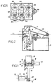
- FIG 2 shows a different application of a device as described above with reference to Figures 6 to 12.
- This device 101 controls the movement horizontal of the folding head 2.
- Figure 1 shows two devices similar to that of Figure 6 driven by a single motor. This last drives two pulleys equivalent to the third pulley 158 in figure 6.
- FIGS. 13 to 15 show another form of realization applied to a folder.
- elements similar to those of FIGS. 1 to 5 carry the same reference increased by 200.
- Figure 13 shows in section a device according to the invention, allowing a head to be moved vertically folding 202 of a folder.
- the latter is intended folding a sheet 204, held between two blank clamps 206.
- One of the 206 blank clamps is movable so that it can release the sheet 204 and is mounted at the end of an arm pivoting 208.
- a device according to the invention controls the movement of this arm 208.
- the folding head 202 is moved using two devices according to the invention, one for its vertical displacement, the other for its displacement horizontal ( Figure 14).
- the movement device 101 horizontal has been described above.
- Figure 15 shows in section the device according to the invention allowing the head to be moved vertically folding device 202. This device is similar to that for moving the blank holder 206.
- the device comprises a lever 278 connected by one of its ends to the folding head 202 (or to the blank holder 206).
- the other end of lever 278 is mounted via an axis connecting finger 214 230 on a cylindrical connecting shaft 216, of axis 228.
- the cylindrical connecting shaft 216 rotates around from its axis, it carries with it the connecting finger 214 through a workout 288 keyed onto the shaft 216.
- 290 bearings allow a relative rotation between the connecting finger 214 and the drive piece 288.
- the cylindrical connecting shaft 216 is mounted on bearings 292 defining first bearings. These bearings are mounted in a bore 294 with axis 234. This axis 234 coincides with axis 228 of the cylindrical shaft of connection 216.
- the bore 294 is produced in a wheel tooth 296 with axis 240, parallel to axis 234 of the bore 294, but offset from it.
- the gear wheel 296 therefore has an eccentric. She is guided in rotation using a second bearing defined by ball bearings 298.
- ball bearings are mounted in a fixed bore relative to the frame 224 of the folder.
- a pinion 300 driven by a motor not shown in the drawing, is mounted on the frame 224 of the folder and meshes with the gear 296.
- FIG 13 two springs 302 and 304 have been represented.
- the first spring 302 is disposed between the arm 208 and the frame 224 of the folder.
- the stiffness of the spring 302 and its compression are determined in such a way so that the force exerted by this spring 302 compensates substantially the weight of the arm 208.
- the power of the motor driving lever 278 can be substantially reduced compared to a machine as shown for example in Figure 4 and not having such a spring.
- the second spring 304 has a similar role. It is mounted between the folding head 202 and the frame 224 of the machine. Like the spring 302 for the arm 208, it allows to balance the weight of the folding head 202.
- the motor of training corresponding to the displacement of the head of folding 202 without exerting any effort can therefore be a motor lower power, compared to a folder of this type but without spring.
- the wheel toothed 296 When it comes to exerting an effort, the wheel toothed 296 is driven by the pinion 300. The toothed wheel 296 then pivots around the axis 240. The axis 234 of bore 294 therefore moves in the plane of the figure 15, due to its eccentricity. This movement is retransmitted via the cylindrical axis of link 216 and link finger 214 to lever 278. More the force to be exerted at the level of the folding head 202 or of the 206 hold down, the greater the eccentricity level of the toothed wheel 296 is low. So with a electric motor, it is possible to exert a force important.
Landscapes
- Engineering & Computer Science (AREA)
- Mechanical Engineering (AREA)
- Transmission Devices (AREA)
- Vehicle Body Suspensions (AREA)
- Support Of The Bearing (AREA)
- Press Drives And Press Lines (AREA)
- Manipulator (AREA)
Description
- un premier ensemble destiné à déplacer la partie de la machine,
- un second ensemble entraíné en rotation sur au moins un second palier,
- une pièce de liaison montée d'une part par l'intermédiaire d'un premier axe de liaison sur le premier ensemble et d'autre part, par l'intermédiaire d'un second axe de liaison sur le second ensemble,
le premier ensemble est un ensemble entraíné en rotation monté sur au moins un premier palier, et en ce que l'axe défini par les premiers paliers est décalé par rapport au premier axe de liaison. Les revendications 11 à 14 concernent l'utilisation du dispositif selon l'invention dans des machines-outil.
Claims (14)
- Dispositif pour déplacer une partie d'une machine (2, 102, 202) et exercer un effort en fin de course comportant :l'axe (40 ; 140 ; 240) défini par le second palier au nombre d'au moins un étant décalé par rapport au second axe de liaison (34 ; 134 ; 234),un premier ensemble (10, 12, 14 ; 142, 144 ; 214, 288) destiné à déplacer la partie de la machine,un second ensemble (18, 22 ; 146, 152 ; 292, 296) entraíné en rotation sur au moins un second palier,une pièce de liaison (16 ; 64 ; 116 ; 216) montée d'une part par l'intermédiaire d'un premier axe de liaison (30 ; 130 ; 230) sur le premier ensemble et d'autre part, par l'intermédiaire d'un second axe de liaison (34 ; 134 ; 234) sur le second ensemble,
caractérisé en ce que le premier ensemble (10, 12, 14 ; 142, 144 ; 214, 288) est un ensemble entraíné en rotation monté sur au moins un premier palier, et en ce que l'axe défini par les premiers paliers (28 ; 128; 228) est décalé par rapport au premier axe de liaison (30 ; 130 ; 230). - Dispositif selon la revendication 1, caractérisé en ce que le premier ensemble comporte un arbre (26) entraíné en rotation au bout duquel est monté un plateau (12) présentant un maneton (14) décalé servant de premier axe (30) de liaison pour la pièce de liaison (16), et en ce que le second ensemble est constitué par un vilebrequin (18) présentant deux paliers de bielles (36) définissant l'axe de liaison (34) de la pièce de liaison et un palier de vilebrequin (38) sur lequel est montée la partie de machine à déplacer (2).
- Dispositif selon la revendication 1, caractérisé en ce que le premier, respectivement le second, ensemble sont constitués par un vilebrequin (142,152) présentant deux paliers constituant les premiers (150), respectivement les seconds (156), paliers et un palier (114,154), placé entre ces deux paliers dont l'axe correspond à l'axe de liaison de la pièce de liaison,en ce que les premiers paliers (150) sont montés dans un bâti fixe (24) de la machine, eten ce que les seconds paliers (156) sont solidaires de la partie (2) de la machine à déplacer.
- Dispositif selon l'une des revendications 1 à 3, caractérisé en ce que le premier ensemble et/ou le second ensemble est monté sur l'arbre de sortie (26) d'un moteur électrique.
- Dispositif selon l'une des revendications 1 à 3, caractérisé en ce que le premier ensemble et/ou le second ensemble est entraíné en rotation par une poulie (144,146) sur laquelle passe une courroie (148), de préférence une courroie crantée.
- Dispositif selon la revendication 5, caractérisé en ce que le premier et le second ensembles sont munis chacun d'une poulie (144,146), les deux poulies étant parallèles à une troisième poulie (158) entraínée par un moteur (160) et une seule courroie crantée (148) transmettant le mouvement de rotation de la troisième poulie aux deux premières.
- Dispositif selon la revendication 1, caractérisé en ce que l'élément de liaison (64) est monté pivotant autour d'un arbre (80) d'axe fixe, les axes de liaison (30;34) et l'axe fixe de l'arbre (80) formant un triangle, et
en ce que les seconds paliers sont réalisés à l'extrémité d'une bielle (66) dont l'autre extrémité est montée pivotante sur un troisième palier fixe (68). - Dispositif selon la revendication 7, caractérisé en ce que l'arbre (80) d'axe fixe est entraíné en rotation et comporte deux poulies crantées, équipées chacune d'un embrayage et en ce que l'une des poulies (74) est reliée par une première courroie crantée (76) au premier ensemble, l'autre (70) étant reliée par une seconde courroie crantée (72) au second ensemble.
- Dispositif selon la revendication 8, caractérisé en ce que l'arbre d'axe fixe (80) comporte une troisième poulie (82) destinée à permettre l'entraínement en rotation de l'arbre à partir d'un moteur d'axe fixe parallèle à l'axe fixe de l'arbre par l'intermédiaire d'une troisième courroie crantée (84).
- Dispositif selon la revendication 1, caractérisé en ce que le premier ensemble comporte un levier (278), relié d'une part à la partie de machine à déplacer (202,206) et d'autre part à un arbre cylindrique (216) par l'intermédiaire d'un premier axe de liaison (230), parallèle mais décalé par rapport à l'arbre cylindrique (216),en ce que le second ensemble comporte une pièce (296) entraínée en rotation autour de l'axe (240) défini par les seconds paliers, cette pièce présentant un alésage (294) d'axe parallèle mais décalé par rapport à l'axe (240) défini par les seconds paliers et servant de logement à des roulements (292), eten ce que les roulements (292) du logement (294) du second ensemble reçoivent l'arbre cylindrique (216) qui entraíne le levier (278) et constitue la pièce de liaison.
- Machine-outil destinée au pliage d'une tôle, dans laquelle une tôle (4;204) est maintenue entre des serre-flans (6;206), et comportant une tête de pliage (2;202) pour plier la tôle maintenue entre les serre-flans, caractérisée en ce que le mouvement de la tête de pliage est commandé par au moins un dispositif selon l'une des revendications 1 à 10.
- Machine-outil destinée au pliage d'une tôle, dans laquelle une tôle (4;204) est maintenue entre des serre-flans (6;206), et comportant une tête de pliage (2;202) pour plier la tôle maintenue entre les serre-flans, caractérisée en ce que le mouvement d'approche et de serrage des serre-flans est commandé par un dispositif selon l'une des revendications 1 à 10.
- Machine-outil comportant un bâti (224) selon l'une des revendications 11 ou 12, caractérisée en ce qu'un ressort (302,304) est placé entre le bâti et une pièce à déplacer, notamment la tête de pliage ou les serre-flans.
- Machine-outil destinée au poinçonnage d'une tôle, comportant un outil de poinçonnage (102), caractérisée en ce que la commande de l'outil de poinçonnage est réalisée par l'intermédiaire d'un dispositif selon l'une des revendications 1 à 10.
Applications Claiming Priority (3)
| Application Number | Priority Date | Filing Date | Title |
|---|---|---|---|
| FR9608639 | 1996-07-05 | ||
| FR9608639A FR2750625B1 (fr) | 1996-07-05 | 1996-07-05 | Dispositif pour deplacer une partie d'une machine et exercer un effort en fin de course |
| PCT/FR1997/001226 WO1998001244A1 (fr) | 1996-07-05 | 1997-07-07 | Dispositif pour deplacer une partie d'une machine et exercer un effort en fin de course |
Publications (2)
| Publication Number | Publication Date |
|---|---|
| EP0918580A1 EP0918580A1 (fr) | 1999-06-02 |
| EP0918580B1 true EP0918580B1 (fr) | 2000-08-16 |
Family
ID=9493921
Family Applications (1)
| Application Number | Title | Priority Date | Filing Date |
|---|---|---|---|
| EP97931892A Expired - Lifetime EP0918580B1 (fr) | 1996-07-05 | 1997-07-07 | Dispositif pour deplacer une partie d'une machine et exercer un effort en fin de course |
Country Status (5)
| Country | Link |
|---|---|
| EP (1) | EP0918580B1 (fr) |
| AT (1) | ATE195447T1 (fr) |
| DE (1) | DE69702860T2 (fr) |
| FR (1) | FR2750625B1 (fr) |
| WO (1) | WO1998001244A1 (fr) |
Families Citing this family (6)
| Publication number | Priority date | Publication date | Assignee | Title |
|---|---|---|---|---|
| JP3085503U (ja) * | 2001-10-22 | 2002-05-10 | 株式会社サルバニーニジャパン | プログラム化した一定の曲げ角度でのシート曲げのための温度補償を有する高効率機械 |
| FR2876926B1 (fr) * | 2004-10-21 | 2008-03-14 | Jean Claude Jeandeaud | Dispositif et installation de pliage d'un flan |
| EP1777017A1 (fr) | 2005-10-21 | 2007-04-25 | Arcelor Steel Service Centres | Dispositif de pliage à bras de pliage positif et négatif indépendants |
| PT2061609E (pt) * | 2006-09-04 | 2011-04-08 | Finn Power Oy | Sistema cinemático para fixação de produtos semi-acabados, por meio de pressão para máquinas de moldagem metálica de revestimentos |
| EP3135393B1 (fr) * | 2015-08-26 | 2018-03-14 | CIDAN Machinery Sweden AB | Mécanisme de transmission excentrique destiné à une machine de pliage |
| SE543695C2 (en) * | 2019-10-15 | 2021-06-08 | Cidan Machinery Sweden Ab | A folding machine for folding sheet shaped material |
Family Cites Families (4)
| Publication number | Priority date | Publication date | Assignee | Title |
|---|---|---|---|---|
| US3795168A (en) * | 1973-01-04 | 1974-03-05 | Gulf & Western Ind Prod Co | Low-impact four-bar press |
| AT363756B (de) * | 1979-06-20 | 1981-08-25 | Krems Huette Gmbh | Biegemaschine |
| IT1222347B (it) * | 1987-07-03 | 1990-09-05 | Antonio Codatto | Pressa piegatrice per lamiere |
| DE9404308U1 (de) * | 1994-03-15 | 1994-07-28 | Blaz, Santic, 86159 Augsburg | Biegemaschine zum rutschlosen Biegebearbeiten von Blechtafeln |
-
1996
- 1996-07-05 FR FR9608639A patent/FR2750625B1/fr not_active Expired - Fee Related
-
1997
- 1997-07-07 DE DE69702860T patent/DE69702860T2/de not_active Expired - Fee Related
- 1997-07-07 WO PCT/FR1997/001226 patent/WO1998001244A1/fr not_active Ceased
- 1997-07-07 AT AT97931892T patent/ATE195447T1/de not_active IP Right Cessation
- 1997-07-07 EP EP97931892A patent/EP0918580B1/fr not_active Expired - Lifetime
Also Published As
| Publication number | Publication date |
|---|---|
| DE69702860D1 (de) | 2000-09-21 |
| WO1998001244A1 (fr) | 1998-01-15 |
| FR2750625B1 (fr) | 1999-01-29 |
| DE69702860T2 (de) | 2001-03-01 |
| ATE195447T1 (de) | 2000-09-15 |
| EP0918580A1 (fr) | 1999-06-02 |
| FR2750625A1 (fr) | 1998-01-09 |
Similar Documents
| Publication | Publication Date | Title |
|---|---|---|
| EP1370388B1 (fr) | Dispositif d'entrainement et outil de serrage equipe d'un tel dispositif | |
| FR2680480A1 (fr) | Machine a couper et a plier une bande de papier imprime. | |
| EP0918580B1 (fr) | Dispositif pour deplacer une partie d'une machine et exercer un effort en fin de course | |
| FR3027541A1 (fr) | Dispositif d'usinage vibratoire ameliore | |
| CH628936A5 (fr) | Dispositif de regulation de la tension d'enroulement du tissu sur une machine a tisser. | |
| FR2554021A1 (fr) | Machine automatique perfectionnee pour cambrer selon une configuration speciale des elements minces et rectilignes, et notamment des fils metalliques | |
| EP0178236A1 (fr) | Machine pour la fabrication de tubes du type présentant une série de déformations à profil hélicoidal pour échangeurs de température et applications analogues | |
| FR2643589A1 (fr) | Machine a couper et a plier une bande de papier imprime | |
| FR2477439A1 (fr) | Cage refouleuse a cylindres reglables en charge | |
| FR2773508A1 (fr) | Dispositif de finition de surfaces peripheriques de disques a came et de cames d'un arbre a cames | |
| FR2489461A1 (fr) | Mecanisme de commande a oscillateur variable | |
| FR2508378A1 (fr) | Installation de decoupe rotative de flans | |
| FR2810381A1 (fr) | Perfectionnement a un actionneur pour embrayage pilote de vehicule automobile | |
| EP0323364A1 (fr) | Tête de travail pour machine de façonnage d'arbres | |
| EP0318353B1 (fr) | Ensemble de rectification des manetons de vilebrequin | |
| EP0370914A1 (fr) | Tête de bridage à rattrapage de jeux | |
| EP0809552B1 (fr) | Machine a evaser des extremites de tubes par bouterollage | |
| EP0095430B1 (fr) | Dispositif perfectionné de transfert à barres | |
| BE667283A (fr) | ||
| FR2467028A1 (fr) | Machine a enrouler les ressorts munie de moyens perfectionnes d'entrainement des rouleaux d'alimentation | |
| FR2774011A1 (fr) | Dispositif de presertissage et/ou de sertissage | |
| BE533032A (fr) | ||
| WO2006042975A1 (fr) | Dispositif et installation de pliage d'un flan | |
| FR2746682A1 (fr) | Machine a cambrer les fils metalliques | |
| EP1010516A1 (fr) | Presse à mécanisme d'entraínement par maneton excentré |
Legal Events
| Date | Code | Title | Description |
|---|---|---|---|
| PUAI | Public reference made under article 153(3) epc to a published international application that has entered the european phase |
Free format text: ORIGINAL CODE: 0009012 |
|
| 17P | Request for examination filed |
Effective date: 19990125 |
|
| AK | Designated contracting states |
Kind code of ref document: A1 Designated state(s): AT BE CH DE ES FI FR GB IT LI NL SE |
|
| GRAG | Despatch of communication of intention to grant |
Free format text: ORIGINAL CODE: EPIDOS AGRA |
|
| 17Q | First examination report despatched |
Effective date: 19990701 |
|
| GRAG | Despatch of communication of intention to grant |
Free format text: ORIGINAL CODE: EPIDOS AGRA |
|
| GRAH | Despatch of communication of intention to grant a patent |
Free format text: ORIGINAL CODE: EPIDOS IGRA |
|
| GRAH | Despatch of communication of intention to grant a patent |
Free format text: ORIGINAL CODE: EPIDOS IGRA |
|
| GRAA | (expected) grant |
Free format text: ORIGINAL CODE: 0009210 |
|
| AK | Designated contracting states |
Kind code of ref document: B1 Designated state(s): AT BE CH DE ES FI FR GB IT LI NL SE |
|
| PG25 | Lapsed in a contracting state [announced via postgrant information from national office to epo] |
Ref country code: NL Free format text: LAPSE BECAUSE OF FAILURE TO SUBMIT A TRANSLATION OF THE DESCRIPTION OR TO PAY THE FEE WITHIN THE PRESCRIBED TIME-LIMIT Effective date: 20000816 Ref country code: FI Free format text: LAPSE BECAUSE OF FAILURE TO SUBMIT A TRANSLATION OF THE DESCRIPTION OR TO PAY THE FEE WITHIN THE PRESCRIBED TIME-LIMIT Effective date: 20000816 Ref country code: ES Free format text: THE PATENT HAS BEEN ANNULLED BY A DECISION OF A NATIONAL AUTHORITY Effective date: 20000816 Ref country code: AT Free format text: LAPSE BECAUSE OF FAILURE TO SUBMIT A TRANSLATION OF THE DESCRIPTION OR TO PAY THE FEE WITHIN THE PRESCRIBED TIME-LIMIT Effective date: 20000816 |
|
| REF | Corresponds to: |
Ref document number: 195447 Country of ref document: AT Date of ref document: 20000915 Kind code of ref document: T |
|
| REG | Reference to a national code |
Ref country code: CH Ref legal event code: EP |
|
| REF | Corresponds to: |
Ref document number: 69702860 Country of ref document: DE Date of ref document: 20000921 |
|
| ITF | It: translation for a ep patent filed | ||
| PG25 | Lapsed in a contracting state [announced via postgrant information from national office to epo] |
Ref country code: SE Free format text: LAPSE BECAUSE OF FAILURE TO SUBMIT A TRANSLATION OF THE DESCRIPTION OR TO PAY THE FEE WITHIN THE PRESCRIBED TIME-LIMIT Effective date: 20001116 |
|
| GBT | Gb: translation of ep patent filed (gb section 77(6)(a)/1977) |
Effective date: 20001026 |
|
| PLBE | No opposition filed within time limit |
Free format text: ORIGINAL CODE: 0009261 |
|
| STAA | Information on the status of an ep patent application or granted ep patent |
Free format text: STATUS: NO OPPOSITION FILED WITHIN TIME LIMIT |
|
| PGFP | Annual fee paid to national office [announced via postgrant information from national office to epo] |
Ref country code: GB Payment date: 20010713 Year of fee payment: 5 Ref country code: FR Payment date: 20010713 Year of fee payment: 5 Ref country code: DE Payment date: 20010713 Year of fee payment: 5 |
|
| PG25 | Lapsed in a contracting state [announced via postgrant information from national office to epo] |
Ref country code: LI Free format text: LAPSE BECAUSE OF NON-PAYMENT OF DUE FEES Effective date: 20010731 Ref country code: CH Free format text: LAPSE BECAUSE OF NON-PAYMENT OF DUE FEES Effective date: 20010731 Ref country code: BE Free format text: LAPSE BECAUSE OF NON-PAYMENT OF DUE FEES Effective date: 20010731 |
|
| 26N | No opposition filed | ||
| REG | Reference to a national code |
Ref country code: GB Ref legal event code: IF02 |
|
| BERE | Be: lapsed |
Owner name: JEANDEAUD JEAN-CLAUDE Effective date: 20010731 |
|
| REG | Reference to a national code |
Ref country code: CH Ref legal event code: PL |
|
| PG25 | Lapsed in a contracting state [announced via postgrant information from national office to epo] |
Ref country code: GB Free format text: LAPSE BECAUSE OF NON-PAYMENT OF DUE FEES Effective date: 20020707 |
|
| PG25 | Lapsed in a contracting state [announced via postgrant information from national office to epo] |
Ref country code: DE Free format text: LAPSE BECAUSE OF NON-PAYMENT OF DUE FEES Effective date: 20030201 |
|
| GBPC | Gb: european patent ceased through non-payment of renewal fee |
Effective date: 20020707 |
|
| PG25 | Lapsed in a contracting state [announced via postgrant information from national office to epo] |
Ref country code: FR Free format text: LAPSE BECAUSE OF NON-PAYMENT OF DUE FEES Effective date: 20030331 |
|
| REG | Reference to a national code |
Ref country code: FR Ref legal event code: ST |
|
| PG25 | Lapsed in a contracting state [announced via postgrant information from national office to epo] |
Ref country code: IT Free format text: LAPSE BECAUSE OF NON-PAYMENT OF DUE FEES;WARNING: LAPSES OF ITALIAN PATENTS WITH EFFECTIVE DATE BEFORE 2007 MAY HAVE OCCURRED AT ANY TIME BEFORE 2007. THE CORRECT EFFECTIVE DATE MAY BE DIFFERENT FROM THE ONE RECORDED. Effective date: 20050707 |