EP0919306A1 - Element a formes differentes et procede et appareil de fabrication d'un corps construit par couches - Google Patents
Element a formes differentes et procede et appareil de fabrication d'un corps construit par couches Download PDFInfo
- Publication number
- EP0919306A1 EP0919306A1 EP98904418A EP98904418A EP0919306A1 EP 0919306 A1 EP0919306 A1 EP 0919306A1 EP 98904418 A EP98904418 A EP 98904418A EP 98904418 A EP98904418 A EP 98904418A EP 0919306 A1 EP0919306 A1 EP 0919306A1
- Authority
- EP
- European Patent Office
- Prior art keywords
- component members
- workpiece
- component
- members
- holes
- Prior art date
- Legal status (The legal status is an assumption and is not a legal conclusion. Google has not performed a legal analysis and makes no representation as to the accuracy of the status listed.)
- Granted
Links
Images





Classifications
-
- B—PERFORMING OPERATIONS; TRANSPORTING
- B23—MACHINE TOOLS; METAL-WORKING NOT OTHERWISE PROVIDED FOR
- B23P—METAL-WORKING NOT OTHERWISE PROVIDED FOR; COMBINED OPERATIONS; UNIVERSAL MACHINE TOOLS
- B23P15/00—Making specific metal objects by operations not covered by a single other subclass or a group in this subclass
- B23P15/24—Making specific metal objects by operations not covered by a single other subclass or a group in this subclass dies
- B23P15/246—Laminated dies
-
- B—PERFORMING OPERATIONS; TRANSPORTING
- B21—MECHANICAL METAL-WORKING WITHOUT ESSENTIALLY REMOVING MATERIAL; PUNCHING METAL
- B21D—WORKING OR PROCESSING OF SHEET METAL OR METAL TUBES, RODS OR PROFILES WITHOUT ESSENTIALLY REMOVING MATERIAL; PUNCHING METAL
- B21D28/00—Shaping by press-cutting; Perforating
- B21D28/02—Punching blanks or articles with or without obtaining scrap; Notching
-
- B—PERFORMING OPERATIONS; TRANSPORTING
- B21—MECHANICAL METAL-WORKING WITHOUT ESSENTIALLY REMOVING MATERIAL; PUNCHING METAL
- B21D—WORKING OR PROCESSING OF SHEET METAL OR METAL TUBES, RODS OR PROFILES WITHOUT ESSENTIALLY REMOVING MATERIAL; PUNCHING METAL
- B21D28/00—Shaping by press-cutting; Perforating
- B21D28/02—Punching blanks or articles with or without obtaining scrap; Notching
- B21D28/10—Incompletely punching in such a manner that the parts are still coherent with the work
-
- B—PERFORMING OPERATIONS; TRANSPORTING
- B21—MECHANICAL METAL-WORKING WITHOUT ESSENTIALLY REMOVING MATERIAL; PUNCHING METAL
- B21D—WORKING OR PROCESSING OF SHEET METAL OR METAL TUBES, RODS OR PROFILES WITHOUT ESSENTIALLY REMOVING MATERIAL; PUNCHING METAL
- B21D35/00—Combined processes according to or processes combined with methods covered by groups B21D1/00 - B21D31/00
-
- B—PERFORMING OPERATIONS; TRANSPORTING
- B23—MACHINE TOOLS; METAL-WORKING NOT OTHERWISE PROVIDED FOR
- B23K—SOLDERING OR UNSOLDERING; WELDING; CLADDING OR PLATING BY SOLDERING OR WELDING; CUTTING BY APPLYING HEAT LOCALLY, e.g. FLAME CUTTING; WORKING BY LASER BEAM
- B23K26/00—Working by laser beam, e.g. welding, cutting or boring
- B23K26/20—Bonding
- B23K26/21—Bonding by welding
- B23K26/22—Spot welding
-
- B—PERFORMING OPERATIONS; TRANSPORTING
- B23—MACHINE TOOLS; METAL-WORKING NOT OTHERWISE PROVIDED FOR
- B23K—SOLDERING OR UNSOLDERING; WELDING; CLADDING OR PLATING BY SOLDERING OR WELDING; CUTTING BY APPLYING HEAT LOCALLY, e.g. FLAME CUTTING; WORKING BY LASER BEAM
- B23K26/00—Working by laser beam, e.g. welding, cutting or boring
- B23K26/20—Bonding
- B23K26/21—Bonding by welding
- B23K26/24—Seam welding
-
- B—PERFORMING OPERATIONS; TRANSPORTING
- B23—MACHINE TOOLS; METAL-WORKING NOT OTHERWISE PROVIDED FOR
- B23P—METAL-WORKING NOT OTHERWISE PROVIDED FOR; COMBINED OPERATIONS; UNIVERSAL MACHINE TOOLS
- B23P15/00—Making specific metal objects by operations not covered by a single other subclass or a group in this subclass
-
- B—PERFORMING OPERATIONS; TRANSPORTING
- B23—MACHINE TOOLS; METAL-WORKING NOT OTHERWISE PROVIDED FOR
- B23P—METAL-WORKING NOT OTHERWISE PROVIDED FOR; COMBINED OPERATIONS; UNIVERSAL MACHINE TOOLS
- B23P2700/00—Indexing scheme relating to the articles being treated, e.g. manufactured, repaired, assembled, connected or other operations covered in the subgroups
- B23P2700/12—Laminated parts
-
- Y—GENERAL TAGGING OF NEW TECHNOLOGICAL DEVELOPMENTS; GENERAL TAGGING OF CROSS-SECTIONAL TECHNOLOGIES SPANNING OVER SEVERAL SECTIONS OF THE IPC; TECHNICAL SUBJECTS COVERED BY FORMER USPC CROSS-REFERENCE ART COLLECTIONS [XRACs] AND DIGESTS
- Y10—TECHNICAL SUBJECTS COVERED BY FORMER USPC
- Y10T—TECHNICAL SUBJECTS COVERED BY FORMER US CLASSIFICATION
- Y10T156/00—Adhesive bonding and miscellaneous chemical manufacture
- Y10T156/10—Methods of surface bonding and/or assembly therefor
- Y10T156/1052—Methods of surface bonding and/or assembly therefor with cutting, punching, tearing or severing
- Y10T156/1056—Perforating lamina
-
- Y—GENERAL TAGGING OF NEW TECHNOLOGICAL DEVELOPMENTS; GENERAL TAGGING OF CROSS-SECTIONAL TECHNOLOGIES SPANNING OVER SEVERAL SECTIONS OF THE IPC; TECHNICAL SUBJECTS COVERED BY FORMER USPC CROSS-REFERENCE ART COLLECTIONS [XRACs] AND DIGESTS
- Y10—TECHNICAL SUBJECTS COVERED BY FORMER USPC
- Y10T—TECHNICAL SUBJECTS COVERED BY FORMER US CLASSIFICATION
- Y10T156/00—Adhesive bonding and miscellaneous chemical manufacture
- Y10T156/10—Methods of surface bonding and/or assembly therefor
- Y10T156/1052—Methods of surface bonding and/or assembly therefor with cutting, punching, tearing or severing
- Y10T156/1062—Prior to assembly
-
- Y—GENERAL TAGGING OF NEW TECHNOLOGICAL DEVELOPMENTS; GENERAL TAGGING OF CROSS-SECTIONAL TECHNOLOGIES SPANNING OVER SEVERAL SECTIONS OF THE IPC; TECHNICAL SUBJECTS COVERED BY FORMER USPC CROSS-REFERENCE ART COLLECTIONS [XRACs] AND DIGESTS
- Y10—TECHNICAL SUBJECTS COVERED BY FORMER USPC
- Y10T—TECHNICAL SUBJECTS COVERED BY FORMER US CLASSIFICATION
- Y10T156/00—Adhesive bonding and miscellaneous chemical manufacture
- Y10T156/10—Methods of surface bonding and/or assembly therefor
- Y10T156/1052—Methods of surface bonding and/or assembly therefor with cutting, punching, tearing or severing
- Y10T156/1062—Prior to assembly
- Y10T156/1075—Prior to assembly of plural laminae from single stock and assembling to each other or to additional lamina
-
- Y—GENERAL TAGGING OF NEW TECHNOLOGICAL DEVELOPMENTS; GENERAL TAGGING OF CROSS-SECTIONAL TECHNOLOGIES SPANNING OVER SEVERAL SECTIONS OF THE IPC; TECHNICAL SUBJECTS COVERED BY FORMER USPC CROSS-REFERENCE ART COLLECTIONS [XRACs] AND DIGESTS
- Y10—TECHNICAL SUBJECTS COVERED BY FORMER USPC
- Y10T—TECHNICAL SUBJECTS COVERED BY FORMER US CLASSIFICATION
- Y10T156/00—Adhesive bonding and miscellaneous chemical manufacture
- Y10T156/12—Surface bonding means and/or assembly means with cutting, punching, piercing, severing or tearing
- Y10T156/13—Severing followed by associating with part from same source
-
- Y—GENERAL TAGGING OF NEW TECHNOLOGICAL DEVELOPMENTS; GENERAL TAGGING OF CROSS-SECTIONAL TECHNOLOGIES SPANNING OVER SEVERAL SECTIONS OF THE IPC; TECHNICAL SUBJECTS COVERED BY FORMER USPC CROSS-REFERENCE ART COLLECTIONS [XRACs] AND DIGESTS
- Y10—TECHNICAL SUBJECTS COVERED BY FORMER USPC
- Y10T—TECHNICAL SUBJECTS COVERED BY FORMER US CLASSIFICATION
- Y10T156/00—Adhesive bonding and miscellaneous chemical manufacture
- Y10T156/12—Surface bonding means and/or assembly means with cutting, punching, piercing, severing or tearing
- Y10T156/1304—Means making hole or aperture in part to be laminated
-
- Y—GENERAL TAGGING OF NEW TECHNOLOGICAL DEVELOPMENTS; GENERAL TAGGING OF CROSS-SECTIONAL TECHNOLOGIES SPANNING OVER SEVERAL SECTIONS OF THE IPC; TECHNICAL SUBJECTS COVERED BY FORMER USPC CROSS-REFERENCE ART COLLECTIONS [XRACs] AND DIGESTS
- Y10—TECHNICAL SUBJECTS COVERED BY FORMER USPC
- Y10T—TECHNICAL SUBJECTS COVERED BY FORMER US CLASSIFICATION
- Y10T156/00—Adhesive bonding and miscellaneous chemical manufacture
- Y10T156/12—Surface bonding means and/or assembly means with cutting, punching, piercing, severing or tearing
- Y10T156/1317—Means feeding plural workpieces to be joined
- Y10T156/1322—Severing before bonding or assembling of parts
-
- Y—GENERAL TAGGING OF NEW TECHNOLOGICAL DEVELOPMENTS; GENERAL TAGGING OF CROSS-SECTIONAL TECHNOLOGIES SPANNING OVER SEVERAL SECTIONS OF THE IPC; TECHNICAL SUBJECTS COVERED BY FORMER USPC CROSS-REFERENCE ART COLLECTIONS [XRACs] AND DIGESTS
- Y10—TECHNICAL SUBJECTS COVERED BY FORMER USPC
- Y10T—TECHNICAL SUBJECTS COVERED BY FORMER US CLASSIFICATION
- Y10T156/00—Adhesive bonding and miscellaneous chemical manufacture
- Y10T156/12—Surface bonding means and/or assembly means with cutting, punching, piercing, severing or tearing
- Y10T156/137—Stamp from multiple row sheet type
-
- Y—GENERAL TAGGING OF NEW TECHNOLOGICAL DEVELOPMENTS; GENERAL TAGGING OF CROSS-SECTIONAL TECHNOLOGIES SPANNING OVER SEVERAL SECTIONS OF THE IPC; TECHNICAL SUBJECTS COVERED BY FORMER USPC CROSS-REFERENCE ART COLLECTIONS [XRACs] AND DIGESTS
- Y10—TECHNICAL SUBJECTS COVERED BY FORMER USPC
- Y10T—TECHNICAL SUBJECTS COVERED BY FORMER US CLASSIFICATION
- Y10T156/00—Adhesive bonding and miscellaneous chemical manufacture
- Y10T156/17—Surface bonding means and/or assemblymeans with work feeding or handling means
- Y10T156/1702—For plural parts or plural areas of single part
- Y10T156/1744—Means bringing discrete articles into assembled relationship
- Y10T156/1751—At least three articles
- Y10T156/1761—Stacked serially
-
- Y—GENERAL TAGGING OF NEW TECHNOLOGICAL DEVELOPMENTS; GENERAL TAGGING OF CROSS-SECTIONAL TECHNOLOGIES SPANNING OVER SEVERAL SECTIONS OF THE IPC; TECHNICAL SUBJECTS COVERED BY FORMER USPC CROSS-REFERENCE ART COLLECTIONS [XRACs] AND DIGESTS
- Y10—TECHNICAL SUBJECTS COVERED BY FORMER USPC
- Y10T—TECHNICAL SUBJECTS COVERED BY FORMER US CLASSIFICATION
- Y10T29/00—Metal working
- Y10T29/49—Method of mechanical manufacture
- Y10T29/49462—Gear making
- Y10T29/49467—Gear shaping
- Y10T29/49472—Punching or stamping
-
- Y—GENERAL TAGGING OF NEW TECHNOLOGICAL DEVELOPMENTS; GENERAL TAGGING OF CROSS-SECTIONAL TECHNOLOGIES SPANNING OVER SEVERAL SECTIONS OF THE IPC; TECHNICAL SUBJECTS COVERED BY FORMER USPC CROSS-REFERENCE ART COLLECTIONS [XRACs] AND DIGESTS
- Y10—TECHNICAL SUBJECTS COVERED BY FORMER USPC
- Y10T—TECHNICAL SUBJECTS COVERED BY FORMER US CLASSIFICATION
- Y10T29/00—Metal working
- Y10T29/49—Method of mechanical manufacture
- Y10T29/49462—Gear making
- Y10T29/49467—Gear shaping
- Y10T29/49478—Gear blank making
-
- Y—GENERAL TAGGING OF NEW TECHNOLOGICAL DEVELOPMENTS; GENERAL TAGGING OF CROSS-SECTIONAL TECHNOLOGIES SPANNING OVER SEVERAL SECTIONS OF THE IPC; TECHNICAL SUBJECTS COVERED BY FORMER USPC CROSS-REFERENCE ART COLLECTIONS [XRACs] AND DIGESTS
- Y10—TECHNICAL SUBJECTS COVERED BY FORMER USPC
- Y10T—TECHNICAL SUBJECTS COVERED BY FORMER US CLASSIFICATION
- Y10T29/00—Metal working
- Y10T29/51—Plural diverse manufacturing apparatus including means for metal shaping or assembling
- Y10T29/5136—Separate tool stations for selective or successive operation on work
- Y10T29/5137—Separate tool stations for selective or successive operation on work including assembling or disassembling station
- Y10T29/5142—Separate tool stations for selective or successive operation on work including assembling or disassembling station and means to sever work from supply
-
- Y—GENERAL TAGGING OF NEW TECHNOLOGICAL DEVELOPMENTS; GENERAL TAGGING OF CROSS-SECTIONAL TECHNOLOGIES SPANNING OVER SEVERAL SECTIONS OF THE IPC; TECHNICAL SUBJECTS COVERED BY FORMER USPC CROSS-REFERENCE ART COLLECTIONS [XRACs] AND DIGESTS
- Y10—TECHNICAL SUBJECTS COVERED BY FORMER USPC
- Y10T—TECHNICAL SUBJECTS COVERED BY FORMER US CLASSIFICATION
- Y10T83/00—Cutting
- Y10T83/04—Processes
- Y10T83/0476—Including stacking of plural workpieces
Definitions
- FIG. 1 is a diagram of assistance in explaining a profile to which this invention is applied: (a) being a front view and (b) a plan view.
- FIG. 2 is cross-sectional shapes of the profile of FIG. 1, viewed from different angles: (a) to (e) being sectional views taken substantially on lines A-A, B-B, C-C, D-D and E-E, respectively, in FIG. 1(a), In FIG. 2, hatching has been omitted for simplicity.
- This invention has also adopted a technical means, in a method for manufacturing a laminate by punching sheet stock into component members having different outer contours corresponding to the cross-sectional shapes of the laminate, and sequentially laminating the component members into the laminate, where a plurality of component members are blanked from sheet stock, together with clearance holes passing through the component members, part of the component members are laminated and welded together by laser welding, the remaining component members are laminated on the laser-welded component members, with the clearance holes positioned to clear weld buildups on the laser-welded component members, and the entire component members are welded together by applying a laser beam onto the areas of the component members other than the clearance holes.
- the manufacturing apparatus for the aforementioned manufacturing method comprises a housing device for housing multiple types of component members having guide holes and clearance holes, a supporting device having guide pins for engaging with the guide holes, a holding and pressing device for extracting and feeding particular component members onto the supporting device, and a laser-beam unit for applying a laser beam so that the component members are sequentially laminated and welded together into a laminate.
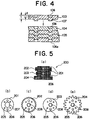
- FIG. 4 is an enlarged longitudinal sectional view illustrating an example of laminating component members in an embodiment of this invention.
- numeral 107 refers to a dowel formed coaxially with the dowel hole 106.
- the dowel hole 106 and the dowel 107 can be formed by using a punch and a die having a circular cross-sectional shape, for example, and making the penetration depth d of the punch into the die smaller than the thickness t of the component members 103 ⁇ 105 (the same applies to the component members 101 and 102 in FIG. 3).
- the dowel hole 106 and the dowel 107 may be formed simultaneously with the blanking of the component members 101 ⁇ 105 in FIG.
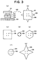
- the profile 200 is formed. That is, a gear portion is formed by the component members 202 and 204, a cam portion by the component member 203 on the outer periphery thereof and a spacer portion by the component member 201 on the upper surface, and between the cam portion and the gear portion.
- the positioning accuracy of the component members 201 ⁇ 204 is further improved by engaging the guide pins with the guide holes 206, in addition to the engagement of the dowels (not shown) with the dowel holes 205.
- the outer surfaces of the cam and gear portions are accurately aligned with each other. This leads to the highly accurate workmanship of the product, making the product fully achieve its functions.
- dowel holes 106 are provided with a similar punch/die set 2, and dowels (not shown. Refer to numeral 107 in FIG. 4.) are provided coaxially with the dowel holes 106.
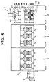
- pilot pins engaging with the pilot holes 6 are provided on the punch/die set 2 so that processing can be carried out by positioning the punch/die set 2 using the pilot holes 6 as reference holes. (The same applies to the punch/die sets used in the subsequent steps.)
- the component members 101 ⁇ 105 are sequentially blanked and pushed back and replaced to the original punched holes on the workpiece 4 while indexing the workpiece 4 at intervals of P.
- five types of the punch/die sets 2 shown in FIG. 6 corresponding to the outer contours of the component members 101 ⁇ 105 are disposed so that these punch/die sets 2 can be selectively actuated.
- Two pieces each, for example, of the component members 101 ⁇ 105 corresponding to the profile 100 shown in FIG. 3 are formed sequentially, as shown in FIG. 9.
- the component members 101 ⁇ 105 thus blanked are pushed back into the punched holes 35 on the workpiece 4, and transported, together with the workpiece 4, to the final stage.
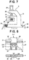
- the component members 101 ⁇ 105 are laminated as they are guided by the punched hole 35 (refer to FIG. 8) which serves as a die.
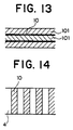
- the adjoining component members can be laminated integrally as the dowels 107 are engaged with the dowel boles 106, as shown in FIG. 4.
- the hole 55 provided on the holding plate 56 on the holding device 52 is formed into a size larger than the maximum outer contour of the component members 101 ⁇ 105 so that any of the component members 101 ⁇ 105 can be passed through the hole 55 without hindrance.
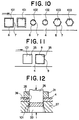
- FIG. 10 is a plan view illustrating the second processing step embodying this invention. Like parts are indicated by like reference numerals used in FIG. 9. In FIG. 10, the pilot holes 6 and dowel holes 106 shown in FIG. 9 are omitted for the sake of simplicity.
- numeral 7 refers to a connecting part formed in a small width on part of the outer contour of a component member 101, for example to connect the workpiece 4 and the component member 101. That is, a slit-shaped punched part 8 is formed by the punch/die set.
- a component member 101 having no rounded edges or burrs on the outer periphery thereof can be blanked by lowering the punch 26, with the stripper 31brought into close contact with the workpiece 4 as the inverted-V-shaped ridge 36 provided on the stripper 31 cuts into the surface of the workpiece 4.
- the component member 101 is pushed back and replaced to the punched hole 35 as the receiving member 33 is pushed upward.
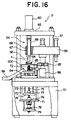
- Numeral 81 refers to a hydraulic cylinder provided on the base 51 for causing an actuating lever 82 to protrude upward.
- Guide pins 84 passing through the table 72 are vertically movably provided on the upper end of the actuating lever 82 via supporting member 83.
- Numerals 85 and 86 refer to a discharging device and a discharging chute, respectively, provided on the base 51 for discharging a profile 200, for example, after laminating and pressure bonding the component members thereof, from the table 72.
- the pressure bonding punch 58 is retracted upward, the workpiece 4 is indexed by one pitch, and the next component member is ejected from the workpiece 4 and placed on the preceding component member in the same manner as described above for lamination and pressure bonding.
- the adjoining component members are laminated and pressure bonded safely and tightly, as shown in FIG. 4 as the dowels 107 are engaged with the dowel holes 106 by the operation of the pressure bonding punch 58.
- the drive motor 80 is left in the inactive state, but the table 72 can be held at that position by bringing the brake device 78 into the braking state.
- the table 72 As the pressing force exerted by the pressure bonding punch 58 when laminating and pressure bonding the component members causes the male thread 75 enmeshed with the female-thread member 77 to rotate via the female-thread member 71, the table 72 is lowered by the thickness of one component member, and stops at that position. In other words, the table 72 on which the aforementioned component members are placed can be repeatedly lowered and stopped sequentially by setting the pressing force exerted by the pressure bonding punch 58 larger than the braking force of the brake device 78.
- a profile 200 can be formed by laminating a predetermined number of component members into one unit.
- the swash cam 129 is selectively moved to a position shown by a chain line in FIG. 18 by operating the air cylinder 130 in the opposite direction. Since this causes the outer pressure bonding punch 123 to be preloaded upward by the compression coil spring 126, the outer pressure bonding punch 123 does not come in contact with the workpiece 4, and only the inner pressure bonding punch 122 is operated by the lowering of the actuating lever 68 to eject the component member from the workpiece 4. Consequently, a component member 102, for example, of a smaller outer contour as shown in FIG. 9 can be smoothly ejected, laminated and pressure bonded.
- the holder 59 is adapted to be rotated around the vertical shaft.
- the holder 59 may be adapted to be moved horizontally.
- a plurality of types of pressure bonding punches 58 provided on the holder 59 and formed into a plurality of cross-sectional outside dimensions smaller than the outer contours of component members connected to the workpiece 4 may be adapted to be selectively operated in accordance with the outer contours of component members.
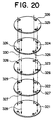
- FIG. 20 is a perspective view showing a method of clearing a weld buildup in an embodiment of this invention.
- numerals 321 ⁇ 325 refer to component members punched from a steel sheet into a circular shape and having four clearance holes 326 near the circumference thereof.
- Numeral 327 refers to weld buildups formed on the same circumference as the clearance boles 326.
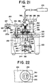
- FIG. 21 is a partially cross-sectional front view illustrating a laminate manufacturing device embodying this invention
- FIG. 22 is an enlarged view taken in the direction of the arrow F in FIG. 21.
- numeral 331 refers to a supporting device supported on a base 332 by a supporting rod 334 and a supporting plate 335 via a base plate 333 provided on the base 332.
- numeral 347 refers to a hydraulic cylinder provided on the base plate 333, with an actuating lever 348 protruded upward.
- actuating lever 348 protruded upward.
- a supporting member 349 On the upper end of the actuating lever 348 provided is a supporting member 349 so that guide pins 351 passing through the table 336 can be vertically moved.
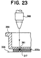
- a gripping member 357 and a pressing member 358 are provided on both ends of an arm 354 fixedly fitted to the upper end of the rotating shaft 353 so that the gripping member 357 and the pressing member 358 are brought above the a housing device 359 and a supporting device 331 by the rotation of the arm 354. That is, the gripping member 357 has claws 360 that are adapted to grip and release a component member 200a housed in the housing device 359.
- the pressing member 358 has through holes 361 allowing a laser beam to pass, and guide holes 362 for engaging with the guide pins 351.
- the table 336 can be stopped at that position by bringing the brake device 342 to the operating state to ensure smooth and positive laser welding.
- the pressing force exerted by the pressing member 358 during the lamination of the component members 200a causes the female thread 341 and the male thread 339 enmeshed therewith to rotate.
- the table 336 is lowered by the thickness of one component member 200a and stopped at that position.
- the guide pins 351 are lowered below the table 336 by operating the hydraulic cylinder 347 to discharge the laminate 200 by a discharging device (not shown).
- the drive motor 345 is operated in the state where the brake device 342 is released to cause the supporting shaft 340 to rotate.
- the engagement of the male thread 339 with the female-thread member 341 causes the table to lift up to the original uppermost position, the drive motor 345 to stop, and the brake device to change to the braking state to hold the table 336 in position.
- the hydraulic cylinder 347 is operated to cause the guide pins 351 to protrude on the table 336, bringing the table 336 to a state ready for receiving the next component member 200a. In subsequent steps, the aforementioned operations are repeated.
Landscapes
- Engineering & Computer Science (AREA)
- Mechanical Engineering (AREA)
- Physics & Mathematics (AREA)
- Optics & Photonics (AREA)
- Plasma & Fusion (AREA)
- Manufacture Of Motors, Generators (AREA)
- Laminated Bodies (AREA)
- Laser Beam Processing (AREA)
Applications Claiming Priority (7)
| Application Number | Priority Date | Filing Date | Title |
|---|---|---|---|
| JP03961897A JP3948575B2 (ja) | 1997-02-25 | 1997-02-25 | 異形部材の製造方法 |
| JP39618/97 | 1997-02-25 | ||
| JP9048625A JPH10244650A (ja) | 1997-03-04 | 1997-03-04 | 積層体の製造方法および製造装置 |
| JP04862497A JP3935236B2 (ja) | 1997-03-04 | 1997-03-04 | 異形部材の製造装置 |
| JP48625/97 | 1997-03-04 | ||
| JP48624/97 | 1997-03-04 | ||
| PCT/JP1998/000729 WO1998037993A1 (fr) | 1997-02-25 | 1998-02-24 | Element a formes differentes et procede et appareil de fabrication d'un corps construit par couches |
Publications (3)
| Publication Number | Publication Date |
|---|---|
| EP0919306A1 true EP0919306A1 (fr) | 1999-06-02 |
| EP0919306A4 EP0919306A4 (fr) | 2005-06-01 |
| EP0919306B1 EP0919306B1 (fr) | 2009-06-24 |
Family
ID=27290197
Family Applications (1)
| Application Number | Title | Priority Date | Filing Date |
|---|---|---|---|
| EP98904418A Expired - Lifetime EP0919306B1 (fr) | 1997-02-25 | 1998-02-24 | procédé et appareil de fabrication de profilés et de laminés |
Country Status (4)
| Country | Link |
|---|---|
| US (1) | US6682625B1 (fr) |
| EP (1) | EP0919306B1 (fr) |
| DE (1) | DE69840926D1 (fr) |
| WO (1) | WO1998037993A1 (fr) |
Cited By (8)
| Publication number | Priority date | Publication date | Assignee | Title |
|---|---|---|---|---|
| WO2003055682A1 (fr) * | 2001-12-25 | 2003-07-10 | Institute Of Technology Precision Electrical Discharge Work's | Procede et systeme de production de lamines |
| WO2004050295A1 (fr) * | 2002-11-27 | 2004-06-17 | Battelle Memorial Institute | Procede de fabrication de dispositifs multicanaux et dispositif multicanaux fabriques |
| EP0958136A4 (fr) * | 1997-11-21 | 2005-01-26 | Means Ind Inc | Pieces stratifiees et leur procede de fabrication |
| WO2006040276A1 (fr) * | 2004-10-07 | 2006-04-20 | Johnson Controls Gmbh | Structure soudee, en particulier de composants de siege |
| DE102006051403B3 (de) * | 2006-10-27 | 2008-02-14 | Johnson Controls Gmbh | Komponente, insbesondere für einen Fahrzeugsitz |
| WO2010125594A1 (fr) * | 2009-04-29 | 2010-11-04 | Ernesto Malvestiti S.P.A. | Procédé et moule pour produire des noyaux ferromagnétiques de moteurs électriques |
| DE102006008401B4 (de) * | 2006-02-21 | 2012-03-01 | Johnson Controls Gmbh | Verstellbeschlag für eine Kraftfahrzeugkomponente |
| CN106944801A (zh) * | 2017-05-11 | 2017-07-14 | 重庆市大足区君治五金工具有限公司 | 一种抹泥板的支架与板体一体成型的工艺 |
Families Citing this family (13)
| Publication number | Priority date | Publication date | Assignee | Title |
|---|---|---|---|---|
| DE502004010706D1 (de) * | 2004-09-02 | 2010-03-18 | Ford Global Tech Llc | Verfahren und Werkzeug zum Stanzen und/oder Formen |
| TW200823513A (en) * | 2006-11-24 | 2008-06-01 | Ind Tech Res Inst | Cholesteric liquid crystal display devices and driving methods thereof |
| US20090188097A1 (en) * | 2008-01-25 | 2009-07-30 | Siemens Power Generation, Inc. | Method of layered fabrication |
| KR20130036592A (ko) * | 2011-10-04 | 2013-04-12 | 삼성디스플레이 주식회사 | 인쇄 회로 필름 모재 제조 방법 및 상기 인쇄 회로 필름을 타발하는 장치 |
| EP2608299B1 (fr) * | 2011-12-22 | 2014-04-09 | Feintool Intellectual Property AG | Dispositif et procédé de fabrication de plaques bipolaires métalliques |
| JP6080288B2 (ja) * | 2012-09-07 | 2017-02-15 | 株式会社放電精密加工研究所 | 積層装置及び積層体製造システム |
| CN107948914B (zh) * | 2017-12-25 | 2024-04-12 | 苏州格洛佛精密科技有限公司 | 焊接机 |
| CN111546559B (zh) * | 2020-06-05 | 2025-01-14 | 廊坊江昊防腐材料有限公司 | 塑料支架串联机 |
| CN112275930B (zh) * | 2020-11-19 | 2025-09-19 | 无锡海特精密模具有限公司 | 一种夹持送料机构及冷冲级进模 |
| CN112959001B (zh) * | 2021-02-01 | 2023-06-23 | 东莞市锦洲科技有限公司 | 一种铝合金型材加工方法 |
| CN114178864B (zh) * | 2021-12-07 | 2023-07-28 | 浙江上虹货架有限公司 | 一种货架横梁配件生产方法及焊接搬运加工中心 |
| CN117718756A (zh) * | 2022-09-02 | 2024-03-19 | 昆山小为云智能科技有限公司 | 一种水冷板模内焊网装置及焊网方法 |
| CN119982724A (zh) * | 2025-04-11 | 2025-05-13 | 温州长隆机械有限公司 | 基于液控单向阀的液压系统节流控制方法 |
Family Cites Families (19)
| Publication number | Priority date | Publication date | Assignee | Title |
|---|---|---|---|---|
| JPS53149855A (en) * | 1977-06-01 | 1978-12-27 | Hitachi Metals Ltd | Laminating of amorphous alloy |
| US4242678A (en) | 1978-07-17 | 1980-12-30 | Dennison Manufacturing Company | Variable size character generation using neighborhood-derived shapes |
| FR2435149A1 (fr) * | 1978-09-01 | 1980-03-28 | Mitsui Mfg Co Ltd | Appareil de formation d'un empilage de feuillets magnetiques |
| US4285754A (en) * | 1979-11-05 | 1981-08-25 | Solid Photography Inc. | Method and apparatus for producing planar elements in the construction of surfaces and bodies |
| US4445272A (en) * | 1980-06-16 | 1984-05-01 | International Business Machines Corporation | Method and apparatus for stacking rotor blanks on a shaft |
| DE3164834D1 (en) * | 1980-06-16 | 1984-08-23 | Ibm | Method of, and apparatus for, manufacturing laminated dynamoelectric machine structures |
| JPH0344346Y2 (fr) * | 1986-08-07 | 1991-09-18 | ||
| US5015312A (en) * | 1987-09-29 | 1991-05-14 | Kinzie Norman F | Method and apparatus for constructing a three-dimensional surface of predetermined shape and color |
| GB8729929D0 (en) * | 1987-12-23 | 1988-02-03 | Lacy R M | Linerless self-adhesive labels |
| FR2640896A1 (en) * | 1988-12-22 | 1990-06-29 | Peugeot | Installation and method for the unpiling (peeling off) of parts which are cut out by punching and are put back into a sheet |
| US5160682A (en) * | 1989-03-09 | 1992-11-03 | Calfee Craig D | Method of manufacturing a composite bicycle frame |
| DE3922518A1 (de) | 1989-07-08 | 1991-01-17 | Bayer Ag | Verfahren zur herstellung von (alpha)-methylbenzyl-substituierten phenolen |
| JP3317727B2 (ja) * | 1992-10-02 | 2002-08-26 | 株式会社放電精密加工研究所 | 順送り加工装置 |
| US6056843A (en) * | 1993-12-29 | 2000-05-02 | Kira Corporation | Sheet lamination modeling method and sheet lamination modeling apparatus |
| JP3497911B2 (ja) | 1995-02-22 | 2004-02-16 | 黒田精工株式会社 | モータ用積層鉄心の製造方法及び金型装置 |
| JPH09163691A (ja) | 1995-12-01 | 1997-06-20 | Toshiba Mec Kk | 積層形コア及びその製造方法 |
| JP3546579B2 (ja) | 1996-02-28 | 2004-07-28 | 松下電器産業株式会社 | 積層金型装置 |
| US5730817A (en) * | 1996-04-22 | 1998-03-24 | Helisys, Inc. | Laminated object manufacturing system |
| US5755023A (en) * | 1996-06-05 | 1998-05-26 | L.H. Carbide Corporation | Lamina stack with at least one lamina layer having a plurality of discrete segments and an apparatus and method for manufacturing said stack |
-
1998
- 1998-02-24 DE DE69840926T patent/DE69840926D1/de not_active Expired - Lifetime
- 1998-02-24 EP EP98904418A patent/EP0919306B1/fr not_active Expired - Lifetime
- 1998-02-24 US US09/171,997 patent/US6682625B1/en not_active Expired - Lifetime
- 1998-02-24 WO PCT/JP1998/000729 patent/WO1998037993A1/fr not_active Ceased
Cited By (11)
| Publication number | Priority date | Publication date | Assignee | Title |
|---|---|---|---|---|
| EP0958136A4 (fr) * | 1997-11-21 | 2005-01-26 | Means Ind Inc | Pieces stratifiees et leur procede de fabrication |
| WO2003055682A1 (fr) * | 2001-12-25 | 2003-07-10 | Institute Of Technology Precision Electrical Discharge Work's | Procede et systeme de production de lamines |
| US6852189B2 (en) | 2001-12-25 | 2005-02-08 | Institute Of Technology Precision Electrical Discharge Work's | Method and apparatus for manufacturing laminates |
| WO2004050295A1 (fr) * | 2002-11-27 | 2004-06-17 | Battelle Memorial Institute | Procede de fabrication de dispositifs multicanaux et dispositif multicanaux fabriques |
| WO2006040276A1 (fr) * | 2004-10-07 | 2006-04-20 | Johnson Controls Gmbh | Structure soudee, en particulier de composants de siege |
| US8187721B2 (en) | 2004-10-07 | 2012-05-29 | Johnson Controls Gmbh | Laser welded seat structure |
| DE102006008401B4 (de) * | 2006-02-21 | 2012-03-01 | Johnson Controls Gmbh | Verstellbeschlag für eine Kraftfahrzeugkomponente |
| DE102006051403B3 (de) * | 2006-10-27 | 2008-02-14 | Johnson Controls Gmbh | Komponente, insbesondere für einen Fahrzeugsitz |
| WO2010125594A1 (fr) * | 2009-04-29 | 2010-11-04 | Ernesto Malvestiti S.P.A. | Procédé et moule pour produire des noyaux ferromagnétiques de moteurs électriques |
| US8912702B2 (en) | 2009-04-29 | 2014-12-16 | Ernesto Malvestiti S.P.A. | Process and mold for producing ferromagnetic cores of electric motors |
| CN106944801A (zh) * | 2017-05-11 | 2017-07-14 | 重庆市大足区君治五金工具有限公司 | 一种抹泥板的支架与板体一体成型的工艺 |
Also Published As
| Publication number | Publication date |
|---|---|
| US6682625B1 (en) | 2004-01-27 |
| WO1998037993A1 (fr) | 1998-09-03 |
| EP0919306B1 (fr) | 2009-06-24 |
| DE69840926D1 (de) | 2009-08-06 |
| EP0919306A4 (fr) | 2005-06-01 |
Similar Documents
| Publication | Publication Date | Title |
|---|---|---|
| US6682625B1 (en) | Method and apparatus for manufacturing profiles and laminates | |
| EP1504896B1 (fr) | Procede et systeme de production de lamines | |
| US8132441B2 (en) | Method and device for fine blanking and forming a workpiece | |
| US4270253A (en) | Apparatus for simultaneous machining of a stack of plate-like workpieces | |
| JP2005103638A (ja) | モータ用積層コアの製造方法、その製造装置、及び積層治具 | |
| EP2893990B1 (fr) | Dispositif de stratification et système de production de stratifié | |
| CN109843465B (zh) | 用于板状工件的多冲程进展式切槽的方法、机床和切槽工具 | |
| JP2006095597A (ja) | パンチプレスのバリ取りツール | |
| JP2007000901A (ja) | パンチプレスのバリ取りツール | |
| EP3299094A1 (fr) | Procédé de fabrication d'une pièce à usiner et outil de découpe/manipulation destiné à exécuter le procédé | |
| JP2011148006A (ja) | パンチプレスのバリ取りツール | |
| JP3317727B2 (ja) | 順送り加工装置 | |
| JP3948575B2 (ja) | 異形部材の製造方法 | |
| EP3247541B1 (fr) | Dispositif pour le perçage des paneaux murales avec douilles d'extraction | |
| JP2829270B2 (ja) | 板状製品のプレス自動製造方法 | |
| US4462147A (en) | Method for simultaneous machining of a stack of plate-like workpieces | |
| JP3935236B2 (ja) | 異形部材の製造装置 | |
| JP4372981B2 (ja) | 積層体の製造方法および製造装置 | |
| JP4191306B2 (ja) | 積層体の製造方法および製造装置 | |
| JP2001009531A (ja) | 積層体の製造装置 | |
| JP4666423B2 (ja) | 異形部材の製造方法および製造装置 | |
| JP2000033433A (ja) | 積層体の製造方法 | |
| US4509395A (en) | Process for precision cutting | |
| US20060277745A1 (en) | Progressive die tool method and apparatus | |
| JP4220590B2 (ja) | 微小寸法の穴および/またはスリットを有する製品の製造方法 |
Legal Events
| Date | Code | Title | Description |
|---|---|---|---|
| PUAI | Public reference made under article 153(3) epc to a published international application that has entered the european phase |
Free format text: ORIGINAL CODE: 0009012 |
|
| 17P | Request for examination filed |
Effective date: 19981122 |
|
| AK | Designated contracting states |
Kind code of ref document: A1 Designated state(s): CH DE FR IT LI |
|
| RAP1 | Party data changed (applicant data changed or rights of an application transferred) |
Owner name: JAPAN SCIENCE AND TECHNOLOGY CORPORATION Owner name: INSTITUTE OF TECHNOLOGY PRECISION ELECTRICAL DISCH |
|
| RIN1 | Information on inventor provided before grant (corrected) |
Inventor name: AOKI, ISAMU, DEPT. OF MECHANICAL ENGINEERING Inventor name: MURATA, CHIKARA, INSTITUTE OF TECHNOLOGY PRECISIO Inventor name: FUTUMURA, SHOJI, INSTITUTE OF TECHNOLOGY PRECISION |
|
| RIC1 | Information provided on ipc code assigned before grant |
Ipc: 7B 23K 26/20 B Ipc: 7B 23P 15/00 B Ipc: 7B 21D 28/22 B Ipc: 7B 21D 35/00 B Ipc: 7B 21D 28/10 B Ipc: 7B 23P 23/04 B Ipc: 7B 21D 28/02 A |
|
| A4 | Supplementary search report drawn up and despatched |
Effective date: 20050420 |
|
| 17Q | First examination report despatched |
Effective date: 20080403 |
|
| RTI1 | Title (correction) |
Free format text: METHOD AND APPARATUS FOR MANUFACTURING PROFILES AND LAMINATES |
|
| GRAP | Despatch of communication of intention to grant a patent |
Free format text: ORIGINAL CODE: EPIDOSNIGR1 |
|
| GRAS | Grant fee paid |
Free format text: ORIGINAL CODE: EPIDOSNIGR3 |
|
| GRAA | (expected) grant |
Free format text: ORIGINAL CODE: 0009210 |
|
| AK | Designated contracting states |
Kind code of ref document: B1 Designated state(s): CH DE FR IT LI |
|
| REG | Reference to a national code |
Ref country code: CH Ref legal event code: EP |
|
| REF | Corresponds to: |
Ref document number: 69840926 Country of ref document: DE Date of ref document: 20090806 Kind code of ref document: P |
|
| REG | Reference to a national code |
Ref country code: CH Ref legal event code: NV Representative=s name: E. BLUM & CO. AG PATENT- UND MARKENANWAELTE VSP |
|
| PLBE | No opposition filed within time limit |
Free format text: ORIGINAL CODE: 0009261 |
|
| STAA | Information on the status of an ep patent application or granted ep patent |
Free format text: STATUS: NO OPPOSITION FILED WITHIN TIME LIMIT |
|
| 26N | No opposition filed |
Effective date: 20100325 |
|
| PGFP | Annual fee paid to national office [announced via postgrant information from national office to epo] |
Ref country code: CH Payment date: 20140212 Year of fee payment: 17 |
|
| REG | Reference to a national code |
Ref country code: FR Ref legal event code: PLFP Year of fee payment: 18 |
|
| PGFP | Annual fee paid to national office [announced via postgrant information from national office to epo] |
Ref country code: DE Payment date: 20150218 Year of fee payment: 18 Ref country code: IT Payment date: 20150209 Year of fee payment: 18 |
|
| PGFP | Annual fee paid to national office [announced via postgrant information from national office to epo] |
Ref country code: FR Payment date: 20150210 Year of fee payment: 18 |
|
| REG | Reference to a national code |
Ref country code: CH Ref legal event code: PL |
|
| PG25 | Lapsed in a contracting state [announced via postgrant information from national office to epo] |
Ref country code: CH Free format text: LAPSE BECAUSE OF NON-PAYMENT OF DUE FEES Effective date: 20150228 Ref country code: LI Free format text: LAPSE BECAUSE OF NON-PAYMENT OF DUE FEES Effective date: 20150228 |
|
| REG | Reference to a national code |
Ref country code: DE Ref legal event code: R119 Ref document number: 69840926 Country of ref document: DE |
|
| REG | Reference to a national code |
Ref country code: FR Ref legal event code: ST Effective date: 20161028 |
|
| PG25 | Lapsed in a contracting state [announced via postgrant information from national office to epo] |
Ref country code: IT Free format text: LAPSE BECAUSE OF NON-PAYMENT OF DUE FEES Effective date: 20160224 |
|
| PG25 | Lapsed in a contracting state [announced via postgrant information from national office to epo] |
Ref country code: DE Free format text: LAPSE BECAUSE OF NON-PAYMENT OF DUE FEES Effective date: 20160901 Ref country code: FR Free format text: LAPSE BECAUSE OF NON-PAYMENT OF DUE FEES Effective date: 20160229 |