EP0919327B1 - Vorrichtung zum Schärfen von Dentalinstrumenten - Google Patents
Vorrichtung zum Schärfen von Dentalinstrumenten Download PDFInfo
- Publication number
- EP0919327B1 EP0919327B1 EP98810336A EP98810336A EP0919327B1 EP 0919327 B1 EP0919327 B1 EP 0919327B1 EP 98810336 A EP98810336 A EP 98810336A EP 98810336 A EP98810336 A EP 98810336A EP 0919327 B1 EP0919327 B1 EP 0919327B1
- Authority
- EP
- European Patent Office
- Prior art keywords
- instrument
- chuck
- head
- disposed
- grinding
- Prior art date
- Legal status (The legal status is an assumption and is not a legal conclusion. Google has not performed a legal analysis and makes no representation as to the accuracy of the status listed.)
- Expired - Lifetime
Links
- 238000006073 displacement reaction Methods 0.000 claims abstract 2
- 238000005520 cutting process Methods 0.000 abstract description 8
- 238000003860 storage Methods 0.000 description 3
- 239000000725 suspension Substances 0.000 description 3
- 238000004519 manufacturing process Methods 0.000 description 2
- 238000000034 method Methods 0.000 description 2
- 238000005498 polishing Methods 0.000 description 2
- 230000006835 compression Effects 0.000 description 1
- 238000007906 compression Methods 0.000 description 1
- 230000001419 dependent effect Effects 0.000 description 1
- 238000007373 indentation Methods 0.000 description 1
- 238000009434 installation Methods 0.000 description 1
- 239000000463 material Substances 0.000 description 1
- 230000003239 periodontal effect Effects 0.000 description 1
Images




Classifications
-
- B—PERFORMING OPERATIONS; TRANSPORTING
- B24—GRINDING; POLISHING
- B24B—MACHINES, DEVICES, OR PROCESSES FOR GRINDING OR POLISHING; DRESSING OR CONDITIONING OF ABRADING SURFACES; FEEDING OF GRINDING, POLISHING, OR LAPPING AGENTS
- B24B3/00—Sharpening cutting edges, e.g. of tools; Accessories therefor, e.g. for holding the tools
- B24B3/60—Sharpening cutting edges, e.g. of tools; Accessories therefor, e.g. for holding the tools of tools not covered by the preceding subgroups
- B24B3/605—Sharpening cutting edges, e.g. of tools; Accessories therefor, e.g. for holding the tools of tools not covered by the preceding subgroups of surgical or dental instruments
-
- B—PERFORMING OPERATIONS; TRANSPORTING
- B24—GRINDING; POLISHING
- B24B—MACHINES, DEVICES, OR PROCESSES FOR GRINDING OR POLISHING; DRESSING OR CONDITIONING OF ABRADING SURFACES; FEEDING OF GRINDING, POLISHING, OR LAPPING AGENTS
- B24B41/00—Component parts such as frames, beds, carriages, headstocks
- B24B41/06—Work supports, e.g. adjustable steadies
-
- A—HUMAN NECESSITIES
- A61—MEDICAL OR VETERINARY SCIENCE; HYGIENE
- A61C—DENTISTRY; APPARATUS OR METHODS FOR ORAL OR DENTAL HYGIENE
- A61C19/00—Dental auxiliary appliances
Definitions
- the present invention relates to a device for sharpening, grinding or polishing dental, Periodontal or surgical instruments according to Preamble of claim 1 (see e.g. DE-A-4307679).
- Such a device is for example in EP-B-0 307 740 specified, an essential feature of this device is the Suspension of the grinding wheel on two supports, which is in a parallelogram connection with four joints arranged are, and this carrier about a vertical axis is rotatable.
- the instrument to be processed is in a Collet clamped, and the collet is in one arcuate arm arranged by means of two supports on Base of the device is supported, the Collet holder around the center of the arch is pivotable to the surface to be sharpened align.
- EP-B-0 513 283 has a similar structure Device for sharpening, grinding and polishing Instruments known, the grinding wheel also in a parallelogram-shaped suspension kept movable while the instrument holder is on two columns suspended and slidable between the columns is arranged.
- EP-A-0 306 267 is a device for sharpening Dental instruments known in which the grinding wheel is rigid is clamped at a certain angle and the Instrument holder with a ball joint Wing nut lock swiveling and around its own axis is rotatably arranged. Contrary to the previously described Arrangements in which the grinding wheel is applied by spring pressure the surface of the instrument to be sharpened is brought up and pivotable around the surface or tip of the instrument is both the grinding wheel and the instrument firmly clamped during the sharpening process, with between a magnetic force on the grinding wheel and the instrument acts and the surface or tip of the instrument within the grinding wheel is pivoted.
- the clamping head holder Simplify instrumentes significantly and thus a To simplify and reduce the cost of production, but without the necessary to sharpen such instruments Compromise precision. This task is accomplished with the Device solved according to independent claim 1. Further improvements and advantages are in the dependent Claims disclosed.
- Figure 3 also shows that the clamping head 1 with respect to Chuck head 3 is rotatable about its central axis, wherein the maximum rotation, for example, 20 ° in each direction and the different positions spring-loaded balls can be snapped into place.
- This Rotary motion is for grinding certain surfaces Instruments necessary, but it can be for other instruments also need other positions or angles of rotation.
- the collet is an important element in one Grinding device, because it is supposed to be clamped precisely and firmly allow a dental instrument. This is also contrary to many known grinders, in which the Grinding wheel clamped in some way and can be aligned, but with the dental instrument is held and guided and possibly only there is a support surface. With such devices hangs the accuracy of the sharpening of the cutting surface in the essential from the skill of the dentist from time to time hardly allows reproducible work. It is therefore necessary to achieve reproducible and accurate Results the instrument in a well-defined Clamp position.
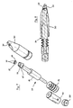
- FIGS. 4 to 11 Some exemplary embodiments are shown in FIGS. 4 to 11 a collet arrangement shown, which is now closer are explained. This can best be done from FIGS Principle of the collet arrangement according to the invention are explained. In it you can see part of one Dental instrument, for example a curette 7, which on first shaft 8 is clamped after the cutting edge 9, the tip 10 of the instrument in Figure 5 or 6 after right, d. H. towards the operator.
- a curette 7 which on first shaft 8 is clamped after the cutting edge 9, the tip 10 of the instrument in Figure 5 or 6 after right, d. H. towards the operator.
- the collet assembly has one in a collet housing 20 running pressure bolt 15, one in the middle Has support part 18.
- a pressure sleeve 11 pushed through a clamping element designed as an eccentric disk 12 Handle 13 is operated.
- This eccentric disc can also be used Wheel or the like may be formed.
- FIG. 5 shows the clamping position and one can see that in this position the positioning bolt 14 in is in the advanced position and for clamping Dental instrument 7 with the back of the cutting edge 9 on it supports to bring about its clear height alignment.
- the instrument is in the clamping opening 21 in the foremost part pushed through the clamping housing, the clamping surface of the Collet opening forms part of the actual collet.
- the clamping surface of the clamping opening can be used with the collet according to FIGS. 5 and 6, for example, a conical one Indentation while the pushpin is rounded End, so that a three-point support of the Instrument shaft can be achieved.
- FIG. 1 A further embodiment variant is shown in FIG shown, the sliding rocker by a resilient element 32 on the pressure pin 33 is replaced while the clamping opening 34 on the clamping housing 35 essentially the is the same as in the previous example.
- element 32 consists of a plate 36, which has an incision 37 from both sides, whereby this plate is both axially and in one can move to some extent transversely to the two Clamping points 38 to the dental instrument as well as possible to be able to adapt.
- the eccentric one works Clamping member 12 not on a pressure sleeve, but on a wheel 39 which is rotatably mounted in a bearing part 40 and connected to the rear part 41 of the pressure pin 33 is.
- the pressure pin is loaded with the same springs as in the previous examples and is shown in FIG Cut and shown in the installed state.
- Figure 11 shows an embodiment variant of Figure 9, wherein the head 42 of the pressure bolt 43 a in the longitudinal axis has extending plate 44, which is so compliant is that the two clamping points 38 also look good can nestle the shaft of the dental instrument to also to ensure its secure mounting.
- the other parts and the installation method correspond to that previous example according to FIGS. 9 and 10.
- the axis of the clamping opening, or clamping surface not is arranged perpendicular to the longitudinal axis of the clamping head, but includes an angle of about 80 °.
- FIG. 12 in particular shows how the Clamping head bracket 3 is attached.
- This is in one Base 45 guided, which has a U-shaped cross section having.
- the base is pulled up.
- the collet holder By pulling the base end up with the It is guide pins and the arrangement of the guide pins possible the collet holder the full range of + 30 ° up and -45 ° down, from the horizontal starting to pivot without the free end of the Bracket protrudes from the turntable.
- the bracket should be managed and kept as free from play as possible. This can be caused, for example, by the Guide pins 51 and 52 fixed in one leg, for example in the leg 47, are arranged and the two other guide pins 48 and 49 spring-loaded are.
- FIG. 12 also shows how the turntable 6, on which the grinding head 4 is arranged with the grinding wheel 5 is rotatably mounted on the base 45.
- On the Surface 53 of base 45 is four bearing plugs 54 arranged, the surfaces with a special lubricious material are coated.
- the turntable runs over a rib 55 on this storage plug.
- the turntable 6 also has a pin 56, as shown in Figure 13, this pin in a not shown Bearing bush runs from the bottom in an appropriate Opening is fixed in the base and as a radial bearing of the turntable is used.
- the Sliding rib 55 connects another rib 57 to the outside, which is not the same height over the entire circumference and thereby a microswitch when turning the turntable 58, see Fig. 4, operated to change the direction of rotation Grinding wheel in certain positions of the turntable reverse. Furthermore, the turntable has on its surface a hand rest 83, see FIG. 1.
- the grinding head 4 has a grinding head housing 68, in the above the grinding wheel 5 and inside the Grinding wheel drive are arranged.
- the Grinding head housing 68 has two at its lower end Bearing parts 69, the plane of which is parallel to the grinding wheel axis are aligned and one on the grinding wheel side
- Is located near the grinding head housing in the two bearing parts 69 each have a second recess 71, the serve to receive a pin 72 on which the tension spring 67 is attached. By dimensioning the tension spring it is possible to achieve the desired and constant grinding pressure on the To manufacture and maintain the grinding wheel.
- FIGs 13 to 15 is also the drive of the Shown grinding wheel. It is preferably a Friction wheel drive used, which is very simple and enables comparatively quiet operation.
- the electric motor 75 has on its output shaft Friction wheel 76, for example with a rubber-elastic ring or an O-ring 77 is equipped.
- the grinding wheel holder 78 has an axis 79 that at two points 80 and 81 in the grinding head housing perpendicular to its longitudinal axis and approximately perpendicular to the output shaft of the electric motor is mounted. On axis 79 is one Friction disk 82 attached to the friction wheel 76th cooperates. The desired speed of rotation the grinding wheel is driven by the speed of the electric Motor and the ratio of the Friction wheels determined to the friction disc.
- the attachment of the grinding wheel on the grinding wheel holder can be accomplished in several ways.
- a friction wheel and a friction disc it is also possible to use an angular gear, whereby on the output shaft of the electric motor Angular gear is arranged on an angular gear the grinding wheel axis acts, for example a 90 ° gear can be used.
Landscapes
- Engineering & Computer Science (AREA)
- Mechanical Engineering (AREA)
- Health & Medical Sciences (AREA)
- General Health & Medical Sciences (AREA)
- Oral & Maxillofacial Surgery (AREA)
- Surgery (AREA)
- Dental Tools And Instruments Or Auxiliary Dental Instruments (AREA)
Priority Applications (9)
| Application Number | Priority Date | Filing Date | Title |
|---|---|---|---|
| EP98810336A EP0919327B1 (de) | 1997-12-01 | 1998-04-17 | Vorrichtung zum Schärfen von Dentalinstrumenten |
| ES98810336T ES2230664T3 (es) | 1997-12-01 | 1998-04-17 | Dispositivo para el afilado de instrumentos dentales. |
| DE59812216T DE59812216D1 (de) | 1997-12-01 | 1998-04-17 | Vorrichtung zum Schärfen von Dentalinstrumenten |
| DK98810336T DK0919327T3 (da) | 1997-12-01 | 1998-04-17 | Indretning til at skærpe dentalinstrumenter |
| AT98810336T ATE281273T1 (de) | 1997-12-01 | 1998-04-17 | Vorrichtung zum schärfen von dentalinstrumenten |
| US09/199,458 US6142856A (en) | 1997-12-01 | 1998-11-25 | Sharpening device for dental instruments |
| BR9804976-3A BR9804976A (pt) | 1997-12-01 | 1998-12-01 | Dispositivo afiador para instrumentos dentários. |
| JP10342051A JPH11226036A (ja) | 1997-12-01 | 1998-12-01 | 歯科または外科用器具を処理する装置 |
| PL98330006A PL189414B1 (pl) | 1997-12-01 | 1998-12-01 | Urządzenie do ostrzenia narzędzi dentystycznych |
Applications Claiming Priority (3)
| Application Number | Priority Date | Filing Date | Title |
|---|---|---|---|
| EP97810935 | 1997-12-01 | ||
| EP97810935 | 1997-12-01 | ||
| EP98810336A EP0919327B1 (de) | 1997-12-01 | 1998-04-17 | Vorrichtung zum Schärfen von Dentalinstrumenten |
Publications (3)
| Publication Number | Publication Date |
|---|---|
| EP0919327A2 EP0919327A2 (de) | 1999-06-02 |
| EP0919327A3 EP0919327A3 (de) | 2002-01-16 |
| EP0919327B1 true EP0919327B1 (de) | 2004-11-03 |
Family
ID=26148100
Family Applications (1)
| Application Number | Title | Priority Date | Filing Date |
|---|---|---|---|
| EP98810336A Expired - Lifetime EP0919327B1 (de) | 1997-12-01 | 1998-04-17 | Vorrichtung zum Schärfen von Dentalinstrumenten |
Country Status (9)
| Country | Link |
|---|---|
| US (1) | US6142856A (da) |
| EP (1) | EP0919327B1 (da) |
| JP (1) | JPH11226036A (da) |
| AT (1) | ATE281273T1 (da) |
| BR (1) | BR9804976A (da) |
| DE (1) | DE59812216D1 (da) |
| DK (1) | DK0919327T3 (da) |
| ES (1) | ES2230664T3 (da) |
| PL (1) | PL189414B1 (da) |
Families Citing this family (14)
| Publication number | Priority date | Publication date | Assignee | Title |
|---|---|---|---|---|
| US6808441B2 (en) | 2003-02-07 | 2004-10-26 | Nordent Manufacturing, Inc. | Dental tool sharpener and method of use |
| CN1921975A (zh) * | 2004-02-19 | 2007-02-28 | 布朗特公司 | 切割链磨削机及磨削方法 |
| TW201036760A (en) * | 2009-03-19 | 2010-10-16 | Siemag Gmbh | Method and device for grinding a continuous casting product |
| CH701550B1 (fr) | 2009-07-16 | 2012-04-13 | Arnold Deppeler | Dispositif et procédé d'affûtage de curettes dentaires. |
| WO2018227378A1 (zh) * | 2017-06-13 | 2018-12-20 | 大连理工大学 | 一种盘类零件外圆柱面精密加工装置及其锥度误差调整方法 |
| CN107225456B (zh) * | 2017-06-28 | 2019-03-22 | 芜湖德丰汽车零部件有限公司 | 一种板材去毛刺打磨装置 |
| CN107150275A (zh) * | 2017-07-14 | 2017-09-12 | 芜湖德丰汽车零部件有限公司 | 一种打磨设备 |
| CN108857888A (zh) * | 2018-07-17 | 2018-11-23 | 益文杰 | 一种瓷砖打磨用固定装置 |
| CN111215971B (zh) * | 2020-03-09 | 2020-12-04 | 深圳市超达成包装制品有限公司 | 一种智能圆刀二次打磨设备 |
| CN113146372B (zh) * | 2020-11-24 | 2022-08-30 | 湖南宏信机械工程有限公司 | 一种机械生产车间加工用钻刀维修养护设备 |
| CN112518484B (zh) * | 2020-11-30 | 2023-01-13 | 天津摩天电子有限公司 | 一种汽车转轴焊接成型表面精细化处理系统 |
| CN112692711A (zh) * | 2020-12-30 | 2021-04-23 | 深圳市杰昌实业有限公司 | 一种金属表面处理抛光装置 |
| CN115302338A (zh) * | 2022-10-12 | 2022-11-08 | 徐州沣收喷灌设备有限公司 | 一种柱塞泵加工用缸体开孔打磨设备 |
| CN116330103B (zh) * | 2023-03-29 | 2025-10-10 | 北京上京医疗器械有限公司 | 义齿曲面加工装置及加工方法 |
Family Cites Families (16)
| Publication number | Priority date | Publication date | Assignee | Title |
|---|---|---|---|---|
| JPS48607Y1 (da) * | 1968-12-14 | 1973-01-09 | ||
| JPS48102389A (da) * | 1972-04-12 | 1973-12-22 | ||
| US3902283A (en) * | 1974-01-18 | 1975-09-02 | Philip D Bean | Gem grinder with approach control means |
| JPS5822218U (ja) * | 1981-07-30 | 1983-02-10 | 日立精機株式会社 | クランプ装置 |
| JPS60127931A (ja) * | 1983-12-15 | 1985-07-08 | Mitsubishi Electric Corp | 産業用ロボツト装置 |
| JPS60155352A (ja) * | 1984-01-24 | 1985-08-15 | Chuo Seisakusho:Kk | T型状ワ−クのための研摩装置 |
| JPS6370837U (da) * | 1986-10-29 | 1988-05-12 | ||
| ES2104555T3 (es) * | 1987-09-04 | 1997-10-16 | Gunnar K Svanberg | Sistema para curetas dentales y maquina de afilado. |
| CH673613A5 (da) * | 1987-09-17 | 1990-03-30 | Mikrona Ag | |
| SE462901B (sv) * | 1988-10-17 | 1990-09-17 | Constr Mining Equip Cme | Anordning foer slipning av stiften paa borrkronor |
| US5058324A (en) * | 1990-01-24 | 1991-10-22 | Snellen Paul F | Gem stone facet forming apparatus |
| US5295328A (en) * | 1990-11-26 | 1994-03-22 | Roswitha Quetin | Device for the sharpening, grinding and polishing of dental, parodental and/or surgical instruments |
| DE9203557U1 (de) * | 1992-03-17 | 1992-09-24 | Hegen, Rudolf, 8073 Kösching | Schleifgerät für zahnärztliche Behandlungsinstrumente |
| JP2500173B2 (ja) * | 1992-04-03 | 1996-05-29 | 住友金属鉱山株式会社 | 曲げ部材切削加工用クランピング装置 |
| JPH0744422Y2 (ja) * | 1992-09-24 | 1995-10-11 | 興和化成株式会社 | 自動調心クランプ装置 |
| US5297362A (en) * | 1992-10-09 | 1994-03-29 | Wykoff Gerald L | Faceting head apparatus for working colored stones |
-
1998
- 1998-04-17 EP EP98810336A patent/EP0919327B1/de not_active Expired - Lifetime
- 1998-04-17 DE DE59812216T patent/DE59812216D1/de not_active Expired - Lifetime
- 1998-04-17 ES ES98810336T patent/ES2230664T3/es not_active Expired - Lifetime
- 1998-04-17 AT AT98810336T patent/ATE281273T1/de not_active IP Right Cessation
- 1998-04-17 DK DK98810336T patent/DK0919327T3/da active
- 1998-11-25 US US09/199,458 patent/US6142856A/en not_active Expired - Lifetime
- 1998-12-01 JP JP10342051A patent/JPH11226036A/ja active Pending
- 1998-12-01 PL PL98330006A patent/PL189414B1/pl not_active IP Right Cessation
- 1998-12-01 BR BR9804976-3A patent/BR9804976A/pt not_active IP Right Cessation
Also Published As
| Publication number | Publication date |
|---|---|
| ES2230664T3 (es) | 2005-05-01 |
| EP0919327A2 (de) | 1999-06-02 |
| DK0919327T3 (da) | 2005-01-31 |
| ATE281273T1 (de) | 2004-11-15 |
| JPH11226036A (ja) | 1999-08-24 |
| PL189414B1 (pl) | 2005-08-31 |
| EP0919327A3 (de) | 2002-01-16 |
| DE59812216D1 (de) | 2004-12-09 |
| US6142856A (en) | 2000-11-07 |
| PL330006A1 (en) | 1999-06-07 |
| BR9804976A (pt) | 1999-11-16 |
Similar Documents
| Publication | Publication Date | Title |
|---|---|---|
| EP0919327B1 (de) | Vorrichtung zum Schärfen von Dentalinstrumenten | |
| EP1127646B1 (de) | Schleifkopf und Sägeblattschleifmaschine mit Hochfrequenz-Spindel | |
| DE69117546T2 (de) | Vorrichtung und Verfahren zur Herstellung von kreisabschnittförmigen Nuten | |
| DE3202362A1 (de) | Vorrichtung zum anschleifen, insbesondere zum ausspitzen eines wendelbohrers | |
| EP0513283B1 (de) | Vorrichtung zum schärfen, schleifen und polieren von dental-, parodontal- und/oder chirurgischen instrumenten | |
| WO2016150665A1 (de) | Spannvorrichtung für eine werkzeugmaschine | |
| DE10235873A1 (de) | Mehrspindel-Werkzeugmaschine | |
| EP0106057A2 (de) | Flachschleifmaschine für Stanzwerkzeuge | |
| EP0080093B1 (de) | Haltevorrichtung für Bohrer zum Schleifen der Schneiden | |
| DE10134505A1 (de) | Wirbelkörperdistraktor | |
| DE4406597A1 (de) | Vorrichtung zum Herstellen von Wandausnehmungen | |
| EP0307740B1 (de) | Gerät zum Schärfen von Paradontalinstrumenten | |
| DE4010635C1 (en) | Grinder-sharpener for dental instruments - has angled holder on carriage with grinding stone between guide members | |
| EP0201789A2 (de) | Vorrichtung zum Schleifen der Schneiden von Bohrern | |
| DE3934365C1 (en) | Grinder tool for dental instruments - has tool body to coaxially enclose support and holder | |
| DE3333169C2 (da) | ||
| EP0172555B1 (de) | Schraubstock | |
| DE2511448A1 (de) | Vorrichtung zum schaerfen von bohrern o.ae., insbesondere spiralbohrern | |
| DE2323737C3 (de) | Vorrichtung zum Gravieren rotationssymmetrischer Werkstücke | |
| DE3110348A1 (de) | Spannfutter fuer ein drehwerkzeug | |
| DE2225136A1 (de) | Verbesserungen an Werkstück-Spannvorrichtungen | |
| DE3205202A1 (de) | Fuehrungsvorrichtung zum arbeiten mit einer kraftmaschine | |
| DE3621392A1 (de) | Adapter zum verbinden eines handfraesgeraetes mit einem staender | |
| DE831368C (de) | Vorrichtung zum Schleifen von Spiralbohrern | |
| DE3743973A1 (de) | Vorrichtung zum bearbeiten zahnaerztlicher oder zahntechnischer werkstuecke |
Legal Events
| Date | Code | Title | Description |
|---|---|---|---|
| PUAI | Public reference made under article 153(3) epc to a published international application that has entered the european phase |
Free format text: ORIGINAL CODE: 0009012 |
|
| AK | Designated contracting states |
Kind code of ref document: A2 Designated state(s): AT BE CH CY DE DK ES FI FR GB GR IE IT LI LU MC NL PT SE |
|
| AX | Request for extension of the european patent |
Free format text: AL;LT;LV;MK;RO;SI |
|
| 18W | Application withdrawn |
Withdrawal date: 19980609 |
|
| PUAL | Search report despatched |
Free format text: ORIGINAL CODE: 0009013 |
|
| D18W | Application withdrawn (deleted) | ||
| AK | Designated contracting states |
Kind code of ref document: A3 Designated state(s): AT BE CH CY DE DK ES FI FR GB GR IE IT LI LU MC NL PT SE |
|
| AX | Request for extension of the european patent |
Free format text: AL;LT;LV;MK;RO;SI |
|
| RIC1 | Information provided on ipc code assigned before grant |
Free format text: 7B 24B 3/60 A, 7A 61C 19/00 B |
|
| 17P | Request for examination filed |
Effective date: 20020701 |
|
| AKX | Designation fees paid |
Free format text: AT BE CH CY DE DK ES FI FR GB GR IE IT LI LU MC NL PT SE |
|
| 17Q | First examination report despatched |
Effective date: 20030912 |
|
| GRAP | Despatch of communication of intention to grant a patent |
Free format text: ORIGINAL CODE: EPIDOSNIGR1 |
|
| GRAS | Grant fee paid |
Free format text: ORIGINAL CODE: EPIDOSNIGR3 |
|
| GRAA | (expected) grant |
Free format text: ORIGINAL CODE: 0009210 |
|
| AK | Designated contracting states |
Kind code of ref document: B1 Designated state(s): AT BE CH CY DE DK ES FI FR GB GR IE IT LI LU MC NL PT SE |
|
| PG25 | Lapsed in a contracting state [announced via postgrant information from national office to epo] |
Ref country code: NL Free format text: LAPSE BECAUSE OF FAILURE TO SUBMIT A TRANSLATION OF THE DESCRIPTION OR TO PAY THE FEE WITHIN THE PRESCRIBED TIME-LIMIT Effective date: 20041103 Ref country code: IE Free format text: LAPSE BECAUSE OF FAILURE TO SUBMIT A TRANSLATION OF THE DESCRIPTION OR TO PAY THE FEE WITHIN THE PRESCRIBED TIME-LIMIT Effective date: 20041103 |
|
| REG | Reference to a national code |
Ref country code: CH Ref legal event code: EP |
|
| REG | Reference to a national code |
Ref country code: CH Ref legal event code: NV Representative=s name: AMMANN PATENTANWAELTE AG BERN |
|
| REF | Corresponds to: |
Ref document number: 59812216 Country of ref document: DE Date of ref document: 20041209 Kind code of ref document: P |
|
| REG | Reference to a national code |
Ref country code: IE Ref legal event code: FG4D Free format text: GERMAN |
|
| REG | Reference to a national code |
Ref country code: DK Ref legal event code: T3 |
|
| PG25 | Lapsed in a contracting state [announced via postgrant information from national office to epo] |
Ref country code: GR Free format text: LAPSE BECAUSE OF FAILURE TO SUBMIT A TRANSLATION OF THE DESCRIPTION OR TO PAY THE FEE WITHIN THE PRESCRIBED TIME-LIMIT Effective date: 20050203 |
|
| GBT | Gb: translation of ep patent filed (gb section 77(6)(a)/1977) |
Effective date: 20050115 |
|
| REG | Reference to a national code |
Ref country code: SE Ref legal event code: TRGR |
|
| PG25 | Lapsed in a contracting state [announced via postgrant information from national office to epo] |
Ref country code: LU Free format text: LAPSE BECAUSE OF NON-PAYMENT OF DUE FEES Effective date: 20050417 Ref country code: CY Free format text: LAPSE BECAUSE OF FAILURE TO SUBMIT A TRANSLATION OF THE DESCRIPTION OR TO PAY THE FEE WITHIN THE PRESCRIBED TIME-LIMIT Effective date: 20050417 Ref country code: AT Free format text: LAPSE BECAUSE OF NON-PAYMENT OF DUE FEES Effective date: 20050417 |
|
| PGFP | Annual fee paid to national office [announced via postgrant information from national office to epo] |
Ref country code: FR Payment date: 20050418 Year of fee payment: 8 |
|
| PGFP | Annual fee paid to national office [announced via postgrant information from national office to epo] |
Ref country code: DK Payment date: 20050425 Year of fee payment: 8 |
|
| PG25 | Lapsed in a contracting state [announced via postgrant information from national office to epo] |
Ref country code: MC Free format text: LAPSE BECAUSE OF NON-PAYMENT OF DUE FEES Effective date: 20050430 Ref country code: BE Free format text: LAPSE BECAUSE OF NON-PAYMENT OF DUE FEES Effective date: 20050430 |
|
| REG | Reference to a national code |
Ref country code: ES Ref legal event code: FG2A Ref document number: 2230664 Country of ref document: ES Kind code of ref document: T3 |
|
| NLV1 | Nl: lapsed or annulled due to failure to fulfill the requirements of art. 29p and 29m of the patents act | ||
| REG | Reference to a national code |
Ref country code: IE Ref legal event code: FD4D |
|
| PLBE | No opposition filed within time limit |
Free format text: ORIGINAL CODE: 0009261 |
|
| STAA | Information on the status of an ep patent application or granted ep patent |
Free format text: STATUS: NO OPPOSITION FILED WITHIN TIME LIMIT |
|
| ET | Fr: translation filed | ||
| 26N | No opposition filed |
Effective date: 20050804 |
|
| BERE | Be: lapsed |
Owner name: HAWE NEOS DENTAL DR. H. V. WEISSENFLUH A.G. Effective date: 20050430 |
|
| PGFP | Annual fee paid to national office [announced via postgrant information from national office to epo] |
Ref country code: GB Payment date: 20060424 Year of fee payment: 9 |
|
| PGFP | Annual fee paid to national office [announced via postgrant information from national office to epo] |
Ref country code: SE Payment date: 20060426 Year of fee payment: 9 Ref country code: ES Payment date: 20060426 Year of fee payment: 9 |
|
| PGFP | Annual fee paid to national office [announced via postgrant information from national office to epo] |
Ref country code: FI Payment date: 20060427 Year of fee payment: 9 |
|
| PG25 | Lapsed in a contracting state [announced via postgrant information from national office to epo] |
Ref country code: DK Free format text: LAPSE BECAUSE OF NON-PAYMENT OF DUE FEES Effective date: 20060501 |
|
| REG | Reference to a national code |
Ref country code: DK Ref legal event code: EBP |
|
| REG | Reference to a national code |
Ref country code: FR Ref legal event code: ST Effective date: 20061230 |
|
| GBPC | Gb: european patent ceased through non-payment of renewal fee |
Effective date: 20070417 |
|
| BERE | Be: lapsed |
Owner name: *HAWE NEOS DENTAL WEISSENFLUH A.G. Effective date: 20050430 |
|
| PG25 | Lapsed in a contracting state [announced via postgrant information from national office to epo] |
Ref country code: PT Free format text: LAPSE BECAUSE OF NON-PAYMENT OF DUE FEES Effective date: 20050403 |
|
| PG25 | Lapsed in a contracting state [announced via postgrant information from national office to epo] |
Ref country code: FI Free format text: LAPSE BECAUSE OF NON-PAYMENT OF DUE FEES Effective date: 20070417 |
|
| PG25 | Lapsed in a contracting state [announced via postgrant information from national office to epo] |
Ref country code: GB Free format text: LAPSE BECAUSE OF NON-PAYMENT OF DUE FEES Effective date: 20070417 Ref country code: FR Free format text: LAPSE BECAUSE OF NON-PAYMENT OF DUE FEES Effective date: 20060502 |
|
| PG25 | Lapsed in a contracting state [announced via postgrant information from national office to epo] |
Ref country code: SE Free format text: LAPSE BECAUSE OF NON-PAYMENT OF DUE FEES Effective date: 20070418 |
|
| REG | Reference to a national code |
Ref country code: ES Ref legal event code: FD2A Effective date: 20070418 |
|
| PG25 | Lapsed in a contracting state [announced via postgrant information from national office to epo] |
Ref country code: ES Free format text: LAPSE BECAUSE OF NON-PAYMENT OF DUE FEES Effective date: 20070418 |
|
| PGFP | Annual fee paid to national office [announced via postgrant information from national office to epo] |
Ref country code: DE Payment date: 20170427 Year of fee payment: 20 Ref country code: CH Payment date: 20170427 Year of fee payment: 20 |
|
| PGFP | Annual fee paid to national office [announced via postgrant information from national office to epo] |
Ref country code: IT Payment date: 20170421 Year of fee payment: 20 |
|
| REG | Reference to a national code |
Ref country code: DE Ref legal event code: R071 Ref document number: 59812216 Country of ref document: DE |
|
| REG | Reference to a national code |
Ref country code: CH Ref legal event code: PL |