EP0919679A1 - Schnappverriegelungseinrichtung, insbesondere für die Befestigung eines Fahrzeugsitzes am Fahrzeugboden - Google Patents
Schnappverriegelungseinrichtung, insbesondere für die Befestigung eines Fahrzeugsitzes am Fahrzeugboden Download PDFInfo
- Publication number
- EP0919679A1 EP0919679A1 EP98402406A EP98402406A EP0919679A1 EP 0919679 A1 EP0919679 A1 EP 0919679A1 EP 98402406 A EP98402406 A EP 98402406A EP 98402406 A EP98402406 A EP 98402406A EP 0919679 A1 EP0919679 A1 EP 0919679A1
- Authority
- EP
- European Patent Office
- Prior art keywords
- locking
- ball
- bolt
- keeper
- safety
- Prior art date
- Legal status (The legal status is an assumption and is not a legal conclusion. Google has not performed a legal analysis and makes no representation as to the accuracy of the status listed.)
- Withdrawn
Links
- 238000006073 displacement reaction Methods 0.000 claims description 7
- 230000000694 effects Effects 0.000 claims description 5
- 230000000903 blocking effect Effects 0.000 claims description 4
- 230000014759 maintenance of location Effects 0.000 claims description 2
- 210000000056 organ Anatomy 0.000 claims description 2
- 208000031968 Cadaver Diseases 0.000 description 8
- 230000006835 compression Effects 0.000 description 6
- 238000007906 compression Methods 0.000 description 6
- 230000000295 complement effect Effects 0.000 description 1
- 238000005553 drilling Methods 0.000 description 1
- 230000005489 elastic deformation Effects 0.000 description 1
- 239000013013 elastic material Substances 0.000 description 1
- 229920001971 elastomer Polymers 0.000 description 1
- 239000000806 elastomer Substances 0.000 description 1
Images


Classifications
-
- E—FIXED CONSTRUCTIONS
- E05—LOCKS; KEYS; WINDOW OR DOOR FITTINGS; SAFES
- E05B—LOCKS; ACCESSORIES THEREFOR; HANDCUFFS
- E05B63/00—Locks or fastenings with special structural characteristics
- E05B63/12—Locks or fastenings with special structural characteristics with means carried by the bolt for interlocking with the keeper
- E05B63/121—Locks or fastenings with special structural characteristics with means carried by the bolt for interlocking with the keeper using balls or the like cooperating with notches
-
- B—PERFORMING OPERATIONS; TRANSPORTING
- B60—VEHICLES IN GENERAL
- B60N—SEATS SPECIALLY ADAPTED FOR VEHICLES; VEHICLE PASSENGER ACCOMMODATION NOT OTHERWISE PROVIDED FOR
- B60N2/00—Seats specially adapted for vehicles; Arrangement or mounting of seats in vehicles
- B60N2/005—Arrangement or mounting of seats in vehicles, e.g. dismountable auxiliary seats
- B60N2/015—Attaching seats directly to vehicle chassis
- B60N2/01508—Attaching seats directly to vehicle chassis using quick release attachments
- B60N2/01516—Attaching seats directly to vehicle chassis using quick release attachments with locking mechanisms
- B60N2/01525—Attaching seats directly to vehicle chassis using quick release attachments with locking mechanisms with locking elements expanding inside or under the vehicle floor or rail
- B60N2/01533—Attaching seats directly to vehicle chassis using quick release attachments with locking mechanisms with locking elements expanding inside or under the vehicle floor or rail using balls interlocking with notches
-
- Y—GENERAL TAGGING OF NEW TECHNOLOGICAL DEVELOPMENTS; GENERAL TAGGING OF CROSS-SECTIONAL TECHNOLOGIES SPANNING OVER SEVERAL SECTIONS OF THE IPC; TECHNICAL SUBJECTS COVERED BY FORMER USPC CROSS-REFERENCE ART COLLECTIONS [XRACs] AND DIGESTS
- Y10—TECHNICAL SUBJECTS COVERED BY FORMER USPC
- Y10T—TECHNICAL SUBJECTS COVERED BY FORMER US CLASSIFICATION
- Y10T403/00—Joints and connections
- Y10T403/59—Manually releaseable latch type
- Y10T403/591—Manually releaseable latch type having operating mechanism
- Y10T403/592—Ball detent
Definitions
- the present invention relates to a snap lock intended in particular for fixing a seat for a vehicle automobile on a floor of this vehicle.
- a lock of the type comprising a bolt comprising a locking body of generally cylindrical shape and latching means of this body in a strike by clamping this strike between a support sleeve and at least one retractable locking ball carried by the locking body, the support sleeve being slidably mounted axially around the locking body by being movable, by cooperation with the keeper, against an elastic restoring force, from a position bolt release, in which the sleeve covers the locking ball by retaining it in the retracted position, towards a bolt locking position, in which the socket and locking ball enclose the keeper.
- a lock of this type is described for example in FR-A-2 735 174 (FR-95 06 868) or FR-A-2 735 810 (FR-95 07 605).
- This type of lock allows for example to hang removably a seat on the passenger compartment floor of a unibody type motor vehicle.
- the body bolt locking system is connected to a seat base and the keeper is secured to the floor.
- the lock sleeve When the seat is unhooked to be notably removed of the vehicle, the lock sleeve may be accidentally moved against its elastic restoring force, for example by impact on a protruding object or by untimely action of somebody. This accidental displacement has the effect to release the locking ball in the projecting position. In this case, the socket can generally no longer return automatically its retracting position of the locking ball. The latter therefore risks being damaged and / or subsequently prevent the correct attachment of the seat on the vehicle floor.
- the object of the invention is to prevent accidental displacement of the sleeve against its elastic force of reminder when the bolt of the lock is separated from the strike.
- the invention relates to a lock on the aforementioned type, characterized in that the bolt further comprises security measures preventing accidental movement from the socket, from its release position to its position locking bolt, other than by cooperation of this socket with the keeper.
- the invention also relates to an arrangement of a lock as defined above, characterized in that the bolt is connected to a motor vehicle seat and the strike is secured to a floor of this vehicle.
- the lock 10 is intended to fix a removable seat for a motor vehicle on a floor 14 (shown in Figures 4 and 5) of the passenger compartment of this vehicle.
- the support 12 of general shape in omega, comprises a core 16 connecting two lugs 18 for attaching this support on a seat base element 20 shown diagrammatically in Figure 1 in phantom.
- the latch 10 comprises a bolt 22 provided with a body of locking 24 in the general shape of a cylindrical pin, intended to be locked by snapping into a hole in lock 26 formed in a keeper 28 fixed in a known manner per se on the floor 14 (see Figures 4 and 5).
- the locking hole 26 extends between two faces opposite 30,32 of the keeper which has a general form of plate.
- the locking body 24 extends through a bore 34 of the support 12. This bore 34 is formed in the core 16 between two opposite faces 36,38 of this core.
- the bolt 22 includes elastic means 40 for pinching opposite faces 36, 38 of the core 16 intended to immobilize the body 24 in the bore 34.
- the pinching means 40 comprise first 42 and second 44 cooperating clamping plates with the two opposite faces 36, 38 of the core 16 respectively, crossed by the locking body 24, and first and second elastic compression members stressing respectively the first 42 and second 44 clamping plates one towards the other.
- the first compression member is a plate 46 in elastic material, for example made of elastomer, deformable according to its thickness, crossed by the locking body 24 and interposed between the first clamping plate 42 and a support head 48 of the body 24 forming one end of the latter.
- clamping plates 42, 44 and the plate elastic 46 have general disc shapes.
- the support head 48 advantageously comprises a axial annular projection 50 intended to sink partially in the compression plate 46 by elastic deformation of it.
- the second compression member is a spring 52 of which the arrangement on the locking body 24 will be described more in detail later.
- the bolt 22 is provided with releasable latching means comprising an axial support sleeve 54 intended to cooperate with a first face 30 of the keeper, said bearing face, and locking balls 56, retractable mounted on the body 24, intended to cooperate with the second face 32 of the keeper, called locking face.
- the bolt 22 has three locking balls 56 housed, in a manner known per se, in angularly spaced radial channels 58 formed in the locking body 24.
- the bolt 22 may include smaller or larger number of balls 56.
- Compression spring 52 surrounds the locking body 24 and is interposed between the second clamping plate 44 and a first end 54A of the socket intended for come to bear against the bearing face 30 of the keeper.
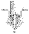
- the sleeve 54 is movable, by cooperation with the keeper 28 and against the elastic return force of the spring 52, from a bolt release position 22, as shown in Figures 1 and 3, towards a position for locking this bolt 22 in the keeper 28, such that shown in Figure 5.
- the socket 54 In its bolt release position 22, the socket 54 covers the locking balls 56 by retaining them in retracted position. In its bolt locking position 22, the sleeve 54 and the locking balls 56 enclose keeper 28.
- the bolt 22 further comprises first and second means for limiting the stroke of the sleeve 54 defining its release and lock positions, respectively of the bolt.
- the first means of limiting the travel of the socket 54 preferably includes a second end 54B of this socket cooperating with an elastic ring (circlip) blocking 60 interposed between this second end 54B and the second clamping plate 44.
- the second means of limiting the travel of the socket 54 preferably include complementary axial stops 64.66 formed on surfaces facing a anti-matting ring 68, carried by the locking body 24, and of the socket 54.
- the anti-matting ring 68 is of the type described in FR-A-2 735 174 (FR-95 06 868).
- the bolt 22 is also provided with displacement means locking balls 56 comprising a needle 70 mounted sliding in an axial bore 72 of the locking body 24. This bore 72 communicates with the radial channels 58.
- the needle 70 for moving the balls is of a type conventional, for example described in FR-A-2 735 810 (FR-95 07 605).
- the needle 70 is elastically stressed towards a position for holding the locking balls 56 in their projecting position, as shown in the Figure 5, by a compression spring 74 interposed between a shoulder 76 of the needle and a bearing 78 for axial guide of this needle attached to an open end of the bore axial 72.
- the needle 70 partially extends through the bearing 78, outside bore 72.
- the outer end 70E of the needle is intended to be connected to means operating classics not shown.
- the bolt 22 further comprises safety means 80 preventing accidental movement of the socket 54 from its release position to its locking position this bolt, other than by cooperation of this socket 54 with strike 28.
- the security means 80 comprise at least one safety ball 82 mounted movable on the locking body 24 between a retracted position in this body 24 authorizing the sliding of the support sleeve 54 along the body 24 (see Figure 5) and a projecting position at the periphery of this body 24 blocking the support sleeve 54 in the covering position of the locking balls 56 (see figure 3).
- Safety ball 82 is housed in both a drilling P, which guides it between its protruding and retracted positions and, in a training light L.
- the guide hole P preferably substantially radial, is formed in the locking body 24. This hole P does not necessarily lead into bore 70.
- the driving light L is formed in an organ driving mobile 84 carried by the bolt 22.
- This drive member 84 preferably having a general shape of flattened cross-section bar rectangular, is slidably mounted in a guide groove 86 substantially axial formed in the locking body 24.
- the drive member 84 extends axially through the head 48 of the locking member, the elastic plate 46, the core 16 of the support, the clamping plates 42, 44 and the support sleeve 54. These various elements crossed by the drive member 84 have a notch or groove clearance for the passage of this member 84.
- drive member 84 extends radially between the locking body 24 and the sleeve support 54.
- the training light L has a first part oblique L1 cooperating by ramp effect with the ball of safety 82 to move it between its protruding positions and retracted, and a second axial part L2 for holding the safety ball 82 in the retracted position.
- the drive member 84 has a first end, said support end 84A, intended to cooperate with keeper 28 (see figures 4 and 5), and a second end 84B solicited by a return spring 88 carried by the bolt 22.
- the spring 88 is housed for example in a cylindrical housing 90 with an axis parallel to that of the needle 70.
- This case 90 has a first end fixed on the head 48 of the locking body, for example by welds 92, as shown in Figure 2.
- the return spring 88 is arranged between a first seat formed by the second end of the housing 90 and a second seat formed by a transverse pin 94 carried by the second end 84B of the drive member.
- the spring 88 resiliently biases the drive member 84, so as to recall the safety ball 82 in its projecting position shown in FIG. 3.
- the support end 84A of the member protrudes axially with respect to at the bearing end 54A of the socket, and on the other hand, is delimited by a very small bearing surface compared to to that of the bearing end 54A of the sleeve.
- the support end 84A of the drive member has a reduced grip which effectively prevents any stress accidental of this drive member 84 to against the return spring 88.
- the stiffness of this spring 88 is preferably chosen so as to prevent displacement of the drive member 84 against its strength recall by manual pressure on its support end 84A.
- the keeper 28 When installing the bolt 22 in the orifice of locking 26, due to the axial offset of the ends support of the drive member 84 and the socket 54, the keeper 28 cooperates successively with these two support ends 84A, 54A.
- the striker 28 first moves the drive member 84 which, through the oblique part L1 light L moves the safety ball 82 from its position protruding towards its retracted position, as shown in Figure 4.
- the sleeve 54 can then slide along of the locking body 24.
- the keeper 28 then moves the socket 54 to its bolt locking position 22, as this is shown in Figure 5.
- the safety ball 82 is kept in its retracted position by the axial part L2 of light L.
- the spring 88 biases elastically the drive member 84 which, by ramp effect of the oblique part L1 of the light L brings back the safety ball 82 in the protruding position for locking the socket 54 in the position covering the locking balls 56.
- this prevents accidental movement of the support sleeve against its elastic return force when the bolt is separated from the striker, this with means simple and inexpensive.
Landscapes
- Engineering & Computer Science (AREA)
- Structural Engineering (AREA)
- Aviation & Aerospace Engineering (AREA)
- Transportation (AREA)
- Mechanical Engineering (AREA)
- Seats For Vehicles (AREA)
- Connection Of Plates (AREA)
- Snaps, Bayonet Connections, Set Pins, And Snap Rings (AREA)
- Lock And Its Accessories (AREA)
Applications Claiming Priority (2)
| Application Number | Priority Date | Filing Date | Title |
|---|---|---|---|
| FR9714948 | 1997-11-27 | ||
| FR9714948A FR2771438B1 (fr) | 1997-11-27 | 1997-11-27 | Verrou a encliquetage destine notamment a la fixation d'un siege pour vehicule automobile sur un plancher de ce vehicule |
Publications (1)
| Publication Number | Publication Date |
|---|---|
| EP0919679A1 true EP0919679A1 (de) | 1999-06-02 |
Family
ID=9513891
Family Applications (1)
| Application Number | Title | Priority Date | Filing Date |
|---|---|---|---|
| EP98402406A Withdrawn EP0919679A1 (de) | 1997-11-27 | 1998-09-30 | Schnappverriegelungseinrichtung, insbesondere für die Befestigung eines Fahrzeugsitzes am Fahrzeugboden |
Country Status (4)
| Country | Link |
|---|---|
| US (1) | US6129324A (de) |
| EP (1) | EP0919679A1 (de) |
| JP (1) | JP3050858B2 (de) |
| FR (1) | FR2771438B1 (de) |
Cited By (3)
| Publication number | Priority date | Publication date | Assignee | Title |
|---|---|---|---|---|
| FR2798628A1 (fr) * | 1999-09-20 | 2001-03-23 | Faure Bertrand Equipements Sa | Articulation robuste pour siege de vehicule automobile et siege muni de cette articulation |
| FR2801255A1 (fr) * | 1999-11-22 | 2001-05-25 | Faure Bertrand Equipements Sa | Ensemble de verrou perfectionne destine notamment a la fixation d'un siege pour vehicule automobile sur un plancher de ce vehicule |
| FR2803866A1 (fr) * | 2000-01-19 | 2001-07-20 | Faure Bertrand Equipements Sa | Ensemble de verrou, notamment pour la fixation d'un siege sur un plancher de vehicule automobile |
Families Citing this family (15)
| Publication number | Priority date | Publication date | Assignee | Title |
|---|---|---|---|---|
| US6234552B1 (en) * | 1999-02-23 | 2001-05-22 | Witte-Velbert Gmbh & Co. Kg | Fastening device for seats, seat benches or the like on the floor of a motor vehicle or the like |
| FR2810929B1 (fr) * | 2000-07-03 | 2002-10-18 | Faure Bertrand Equipements Sa | Dispositif d'assise pour vehicule |
| FR2817596B1 (fr) * | 2000-12-06 | 2003-09-19 | Faurecia Sieges Automobile | Systeme d'assemblage au moyen d'un dispositif d'ancrage a billes |
| KR20020047674A (ko) * | 2000-12-13 | 2002-06-22 | 이계안 | 더블 폴딩시트의 록킹장치 |
| KR20030024303A (ko) * | 2001-09-17 | 2003-03-26 | 현대자동차주식회사 | 자동차용 시트의 탈부착 장치 |
| KR20030030103A (ko) * | 2001-10-08 | 2003-04-18 | 현대자동차주식회사 | 더블 폴딩 시트 장착구조 |
| FR2832105B1 (fr) | 2001-11-09 | 2004-01-30 | Faurecia Sieges Automobile | Siege de vehicule comprenant un dispositif d'assistance et vehicule equipe d'un tel siege |
| DE10158595C1 (de) * | 2001-11-29 | 2003-07-10 | Faurecia Autositze Gmbh & Co | Schwenklagerung einer umklappbaren Fondsitzlehne |
| DE10207372B4 (de) * | 2002-02-22 | 2005-12-15 | Faurecia Autositze Gmbh & Co. Kg | Verriegelungsvorrichtung für eine Sitzstruktur |
| GB2388314B (en) * | 2002-05-10 | 2005-12-21 | Alan Glaser | Chair control arrangement |
| EP2108541B1 (de) | 2007-01-31 | 2011-02-23 | Toyota Boshoku Kabushiki Kaisha | Kraftfahrzeugsitzverstaustruktur |
| US9677582B2 (en) * | 2015-01-09 | 2017-06-13 | Northrop Grumman Systems Corporation | Fluid-actuated fastening device |
| US11712113B2 (en) * | 2018-01-14 | 2023-08-01 | Norix Group, Inc. | Intensive use furniture |
| US10773817B1 (en) | 2018-03-08 | 2020-09-15 | Northrop Grumman Systems Corporation | Bi-directional flow ram air system for an aircraft |
| JP6689345B1 (ja) * | 2018-11-01 | 2020-04-28 | 川田工業株式会社 | 親綱支柱 |
Citations (2)
| Publication number | Priority date | Publication date | Assignee | Title |
|---|---|---|---|---|
| FR2735174A1 (fr) | 1995-06-09 | 1996-12-13 | Cesa | Verrou destine notamment a la fixation d'un siege pour vehicule automobile sur un plancher de ce vehicule |
| FR2735810A1 (fr) | 1995-06-23 | 1996-12-27 | Cesa | Verrou perfectionne destine notamment a la fixation d'un siege pour vehicule automobile sur un plancher de ce vehicule |
Family Cites Families (8)
| Publication number | Priority date | Publication date | Assignee | Title |
|---|---|---|---|---|
| DE3501262C1 (de) * | 1985-01-16 | 1986-07-17 | Jean Walterscheid Gmbh, 5204 Lohmar | In Offenstellung arretierbarer Ziehverschluss |
| US4906123A (en) * | 1988-03-02 | 1990-03-06 | Wes-Tech, Inc. | Quick changecoupling system for robotic attachments |
| US5248134A (en) * | 1992-02-21 | 1993-09-28 | General Motors Corporation | Snap-in upper mount assembly and method of use |
| FR2697932B1 (fr) * | 1992-11-10 | 1995-01-13 | Neopost Ind | Machine à affranchir modulaire comportant un dispositif d'assemblage de modules à centrage et verrouillage automatique. |
| FR2699973B1 (fr) * | 1992-12-29 | 1995-03-17 | Europ Sieges Automobiles | Verrou à enclenchement de préférence automatique et son application notamment à un siège amovible de véhicule. |
| US5390571A (en) * | 1993-03-05 | 1995-02-21 | Fox, Iii; Leonard J. | Push button socket locking mechanism |
| US5542273A (en) * | 1994-11-23 | 1996-08-06 | Bednarz; James W. | Positive acting barrel lock |
| US5586794A (en) * | 1994-12-21 | 1996-12-24 | Stillwagon; Woodrow C. | Resealable fastening device |
-
1997
- 1997-11-27 FR FR9714948A patent/FR2771438B1/fr not_active Expired - Fee Related
-
1998
- 1998-09-30 EP EP98402406A patent/EP0919679A1/de not_active Withdrawn
- 1998-11-02 US US09/184,076 patent/US6129324A/en not_active Expired - Fee Related
- 1998-11-27 JP JP10337778A patent/JP3050858B2/ja not_active Expired - Fee Related
Patent Citations (2)
| Publication number | Priority date | Publication date | Assignee | Title |
|---|---|---|---|---|
| FR2735174A1 (fr) | 1995-06-09 | 1996-12-13 | Cesa | Verrou destine notamment a la fixation d'un siege pour vehicule automobile sur un plancher de ce vehicule |
| FR2735810A1 (fr) | 1995-06-23 | 1996-12-27 | Cesa | Verrou perfectionne destine notamment a la fixation d'un siege pour vehicule automobile sur un plancher de ce vehicule |
Cited By (3)
| Publication number | Priority date | Publication date | Assignee | Title |
|---|---|---|---|---|
| FR2798628A1 (fr) * | 1999-09-20 | 2001-03-23 | Faure Bertrand Equipements Sa | Articulation robuste pour siege de vehicule automobile et siege muni de cette articulation |
| FR2801255A1 (fr) * | 1999-11-22 | 2001-05-25 | Faure Bertrand Equipements Sa | Ensemble de verrou perfectionne destine notamment a la fixation d'un siege pour vehicule automobile sur un plancher de ce vehicule |
| FR2803866A1 (fr) * | 2000-01-19 | 2001-07-20 | Faure Bertrand Equipements Sa | Ensemble de verrou, notamment pour la fixation d'un siege sur un plancher de vehicule automobile |
Also Published As
| Publication number | Publication date |
|---|---|
| FR2771438A1 (fr) | 1999-05-28 |
| FR2771438B1 (fr) | 2000-02-11 |
| US6129324A (en) | 2000-10-10 |
| JPH11230138A (ja) | 1999-08-27 |
| JP3050858B2 (ja) | 2000-06-12 |
Similar Documents
| Publication | Publication Date | Title |
|---|---|---|
| EP0747554B1 (de) | Verriegelung, inbesondere zum Befestigen eines Autositzes am Kraftfahrzeugboden | |
| FR2771438A1 (fr) | Verrou a encliquetage destine notamment a la fixation d'un siege pour vehicule automobile sur un plancher de ce vehicule | |
| FR2817596A1 (fr) | Systeme d'assemblage au moyen d'un dispositif d'ancrage a billes | |
| EP1904362B1 (de) | Verfahren zur montage einer kraftfahrzeugachse mit aufhängungsarmen und montiertem querträger zwischen den armen und entsprechende achse | |
| EP0497655A1 (de) | Radzierblende, insbesondere für Kraftfahrzeuge | |
| EP0750087B1 (de) | Verbesserte Verriegelung, insbesondere zum Befestigen eines Autositzes am Kraftfahrzeugboden | |
| FR2538058A1 (fr) | Mecanisme d'embrayage, notamment pour vehicule automobile | |
| WO2022003089A1 (fr) | Volant de véhicule équipé d'un module de sécurité | |
| FR2768203A1 (fr) | Securite d'engagement a basculement d'un dispositif de maintien en position d'un systeme de serrage de deux elements | |
| FR2745340A1 (fr) | Attache rapide de type a baionnette | |
| FR2786520A1 (fr) | Verrou et agencement de ce verrou dans un support | |
| WO2004088151A2 (fr) | Dispositif de fixation liberable de deux pieces de vehicule automobile, piece de vehicule comprenant une partie d'un tel dispositif, et utilisation d'un tel dispositif | |
| FR2771439A1 (fr) | Agencement d'un verrou dans un support | |
| FR2932857A1 (fr) | Agrafe. | |
| EP1555176A1 (de) | Positionier- und Befestigunseinrichtung für zwei mechanische Teile, Fahrzeuganordnung mit einer solchen Einrichtung und Fahrzeug mit einer solchen Anordnung | |
| EP1552994B1 (de) | Lösbare Vorrichtung zur Ausrichtung und Befestigung von zwei mechanischen Teilen, Fahrzeuganordnung mit einer solchen Vorrichtung und derartiges Fahrzeug mit einer solchen Anordnung | |
| FR2793199A1 (fr) | Ensemble de verrou destine notamment a la fixation d'un siege pour vehicule automobile sur un plancher de ce vehicule et piece pour cet ensemble | |
| EP0821171A1 (de) | Bajonett-Schnellkupplung zum Verbindung zweier Lenkungsteile eines Kraftfahrzeugs | |
| FR2794821A1 (fr) | Ensemble de verrouillage destine notamment a l'accrochage d'un siege de vehicule automobile sur un plancher de ce vehicule | |
| FR2803866A1 (fr) | Ensemble de verrou, notamment pour la fixation d'un siege sur un plancher de vehicule automobile | |
| FR3118106A1 (fr) | Dispositif de fixation | |
| EP4416397B1 (de) | Befestigungsvorrichtung | |
| EP0794337A1 (de) | Bajonettschnellkupplung | |
| EP1134136B1 (de) | Montageverfahren für eine Handbremse und Vorrichtung zur Durchführung des Verfahrens | |
| FR2658878A1 (fr) | Dispositif de connexion rapide entre deux portions d'une timonerie, notamment pour vehicule automobile. |
Legal Events
| Date | Code | Title | Description |
|---|---|---|---|
| PUAI | Public reference made under article 153(3) epc to a published international application that has entered the european phase |
Free format text: ORIGINAL CODE: 0009012 |
|
| 17P | Request for examination filed |
Effective date: 19990331 |
|
| AK | Designated contracting states |
Kind code of ref document: A1 Designated state(s): DE GB IT |
|
| AX | Request for extension of the european patent |
Free format text: AL;LT;LV;MK;RO;SI |
|
| AKX | Designation fees paid |
Free format text: DE GB IT |
|
| RAP1 | Party data changed (applicant data changed or rights of an application transferred) |
Owner name: FAURECIA SIEGES D'AUTOMOBILES S.A. |
|
| GRAH | Despatch of communication of intention to grant a patent |
Free format text: ORIGINAL CODE: EPIDOS IGRA |
|
| STAA | Information on the status of an ep patent application or granted ep patent |
Free format text: STATUS: THE APPLICATION IS DEEMED TO BE WITHDRAWN |
|
| 18D | Application deemed to be withdrawn |
Effective date: 20030128 |