EP0919887A2 - Pièce d'horlogerie avec élément thermo-électrique - Google Patents
Pièce d'horlogerie avec élément thermo-électrique Download PDFInfo
- Publication number
- EP0919887A2 EP0919887A2 EP98309676A EP98309676A EP0919887A2 EP 0919887 A2 EP0919887 A2 EP 0919887A2 EP 98309676 A EP98309676 A EP 98309676A EP 98309676 A EP98309676 A EP 98309676A EP 0919887 A2 EP0919887 A2 EP 0919887A2
- Authority
- EP
- European Patent Office
- Prior art keywords
- circuit
- thermoelectric element
- power
- hand
- display
- Prior art date
- Legal status (The legal status is an assumption and is not a legal conclusion. Google has not performed a legal analysis and makes no representation as to the accuracy of the status listed.)
- Granted
Links
Images









Classifications
-
- G—PHYSICS
- G04—HOROLOGY
- G04G—ELECTRONIC TIME-PIECES
- G04G19/00—Electric power supply circuits specially adapted for use in electronic time-pieces
- G04G19/08—Arrangements for preventing voltage drop due to overloading the power supply
-
- G—PHYSICS
- G04—HOROLOGY
- G04C—ELECTROMECHANICAL CLOCKS OR WATCHES
- G04C10/00—Arrangements of electric power supplies in time-pieces
Definitions
- the present invention relates to an electronic timepiece for storing energy generated by a thermoelectric element in a secondary battery and operating using generated power as well as energy of the secondary battery. It is concerned with effective use of generated power in accordance with power conservation and has means for alerting a user to low power generation or deficiency in the energy of the secondary battery.
- Fig. 2 shows a view of a structure of a thermoelectric element used in a conventional electronic timepiece having a thermoelectric element.
- a number of n-type semiconductors 203 and p-type semiconductors 204 are installed between a heat absorbing side substrate 202 and a heat radiating side substrate 201.
- the n-type semiconductors 203 and the p-type semiconductors 204 are alternately and electrically connected in series by electrodes 205 installed at the heat absorbing side substrate 202 and the heat radiating side substrate 201 and both ends of the element are provided with a respective lead 206.
- the heat absorbing side substrate 202 is thermally coupled with a rear lid of the electronic timepiece which is in touch with the users arm.
- the temperature of the users arm is generally higher than air temperature.
- the heat radiating side substrate 201 is thermally coupled with a timepiece case radiating heat to the atmosphere. When a temperature difference is caused between the heat absorbing side substrate 292 and the heat radiating side substrate 201, an electromotive force is generated by the Seebeck effect.
- thermoelectric element 101 having a structure shown by Fig. 2
- the emf is boosted by the booster circuit 302 and is stored in a storage mechanism 103.
- Electric energy stored in the storage mechanism 103 provides the power source for a timepiece unit 110.
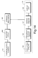
- the timepiece unit 110 is constituted by: an oscillating circuit 105, using quartz having a frequency of 32 kHz or the like; a frequency dividing circuit 106, for dividing the oscillation signal into a signal having a period of 1 Hz and so on; a display driving circuit 107, for driving a step motor for display in accordance with a divided output; and a display unit 108 comprising the step motor, a wheel train and display hands.
- thermoelectric element 101 when the thermoelectric element 101 generates electricity, power consumption of the timepiece unit 110 is supplied by energy from the thermoelectric element 101 and any surplus energy is stored in the storage mechanism 103.
- the storage mechanism 103 supplies power to the timepiece unit 110. Energy held by the storage mechanism 103 is thus reduced and the voltage of the storage mechanism 103 is gradually lowered. In the range of voltage by which the timepiece can be operated, naturally energy necessary for operation of the timepiece is taken out from the storage mechanism 103. Further, even after the motor is stopped and the operation of the timepiece is stopped, a certain degree of current flows and energy from the storage mechanism 103 continues to be discharged. The voltage continues to lower. When the voltage of the storage mechanism 103 drops to a level of about 0.6 V at which current does not flow to the timepiece unit 110, lowering of the voltage is stopped and the voltage is then substantially maintained.
- thermoelectric element when power generation of the thermoelectric element is stopped for a long period of time, the voltage of the storage mechanism is lowered to about 0.6 V and even when power generation by the thermoelectric element restarts and starts to charge the storage mechanism, an extremely long time period is needed until the voltage reaches about 1.0 V by which the timepiece can be operated normally.
- the time period for the voltage to reach 1.0 V is dependent on the power generation capability and capacity of the charge mechanism; when the charge capacity is equal to an amount for operating the timepiece for six months, several days are required for the voltage to reach 1.0 V.
- the timepiece When the timepiece is detached from the users arm before the voltage reaches about 1.0 V, the timepiece is immediately stopped without being able to utilise the energy of the storage mechanism. That is, in order for the timepiece to continue operating even when it is detached from the users arm, power generation of the thermoelectric element needs to continue for several days. But, it is highly probable that the power generation is interrupted in the midst of this power generation.
- thermoelectric element stops generating electricity it is preferable to inform the user of stoppage of power generation when the thermoelectric element stops generating electricity. It is also preferable to inform a user when the remaining amount of energy in the storage mechanism is low. It is preferable to carry out the display in a mode in which power consumption is reduced more than in the normal display mode.
- an electronic timepiece having a thermoelectric element comprises: a thermoelectric element, a storage mechanism for storing an electromotive force from the thermoelectric element or for storing a power produced by boosting an output from the thermoelectric element by a booster circuit, an oscillating circuit, a frequency dividing circuit or a time information calculating circuit, a display driving circuit, a display unit and in addition thereto, a power monitoring circuit for monitoring the situation of at least either one of generated power and stored energy by measuring the generated voltage or current of the thermoelectric element or the output voltage or current of the booster circuit or the voltage of the storage mechanism, an operation stopping circuit or a display drive controlling circuit for controlling operation of the oscillating circuit or the frequency dividing circuit or the time information calculating circuit of the display driving circuit by a detected output of the power monitoring circuit, in which when the power monitoring circuit detects stoppage of power generation by the thermoelectric element or a deficiency in stored energy of the storage mechanism, in order to
- a counting circuit for counting the time period duration of the power generation.
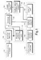
- Fig. 1 is a block diagram showing a first embodiment of an electronic timepiece having a thermoelectric element according to the present invention.
- Fig. 2 is a view of a structure of a thermoelectric element used in an electronic timepiece.
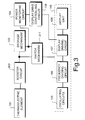
- Fig. 3 is a block diagram showing a second embodiment of an electronic timepiece having a thermoelectric element according to the present invention.
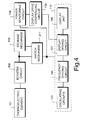
- Fig. 4 is a block diagram showing another embodiment of an electronic timepiece having a thermoelectric element according to the present invention.
- Fig. 5 is block diagram showing another embodiment of an electronic timepiece having a thermoelectric element according to the present invention.
- Fig. 6 is a block diagram showing another embodiment of an electronic timepiece having a thermoelectric element according to the present invention.
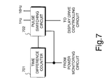
- Fig. 7 is a block diagram showing an inner constitution of a time correction controlling circuit used in the embodiment of the present invention of Fig. 6.
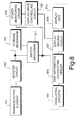
- Fig. 8 is a block diagram showing another embodiment of an electronic timepiece having a thermoelectric element according to the present invention.
- Fig. 9 is a view showing a display state of a display unit used in the embodiment of Fig. 8.
- Fig. 10 is a block diagram showing another embodiment of an electronic timepiece having a thermoelectric element according to the present invention.
- Fig. 11 is block diagram showing another embodiment of an electronic timepiece having a thermoelectric element according to the present invention.
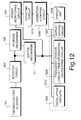
- Fig. 12 is a block diagram showing another embodiment of an electronic timepiece having a thermoelectric element according to the present invention.
- Fig. 13 is a block diagram showing another embodiment of an electronic timepiece having a thermoelectric element according to the present invention.
- Fig. 14 is a block diagram showing a conventional example.
- Fig. 15 is a block diagram showing an embodiment of an electronic timepiece having a thermoelectric element according to the present invention.
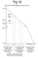
- Fig. 16 is a diagram showing a relationship between stored energy of a storage mechanism and a position of stopping an indicating hand used in the embodiment of Fig. 15.
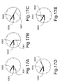
- Figs. 17A-17E show diagrams indicating examples of positions for stopping indicating hands used in the embodiment of Fig. 15.
- Figs. 18A-18B show views of examples of positions of stopping indicating hands used in another embodiment of Fig. 15.
- Fig. 19 is a block diagram showing another embodiment of an electronic timepiece having a thermoelectric element according to the present invention.
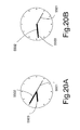
- Figs. 20A-20B show views indicating examples of time display used in the embodiment of Fig. 19.
- thermoelectric element An explanation will be given of a first embodiment of an electronic timepiece having a thermoelectric element according to the present invention with reference to the block diagram of Fig. 1.
- thermoelectric element 101 is similar to that in the conventional case and is provided with a structure shown by the structural view of Fig. 2.
- voltage generated by the thermoelectric element 101 in the case in which a material of Bi-Te-base is used for the n-type semiconductors 203 and the p-type semiconductors 204 constituting the thermoelectric element 101, the number of the p-type and the n-type are respectively 1000 and a temperature difference of 2°C is provided between the heat absorbing side substrate 202 and the heat radiating side substrate 201, an output of about 0.8 V is provided under no load. However, when load is connected, the voltage is lowered to about 0.4 V.
- the generated voltage of 0.4 V is transmitted to a booster circuit 102.
- the inside of the booster circuit 102 is divided into a booster unit 111 and a reverse current preventing unit 112.
- the booster unit 111 is constituted by a charge pump using a condenser or by using counter electromotive force of coil. It carries out boosting of about 4 times and provides an output of about 1.5 V.
- the output of 1.5 V is transmitted to and stored in the storage mechanism 103 via the reverse current preventing unit 112.
- the reverse current preventing unit 112 is for preventing generation of wasteful power consumption caused by reverse flow of stored energy from the storage mechanism 103 to the booster unit 111 when the thermoelectric element 101 does not generate electricity.
- a lithium secondary battery for example, a carbon-lithium secondary battery, a vanadium-lithium secondary battery or a large capacity condenser of an electric double layer condenser or the like can be used; in this case, a lithium secondary battery of 1.5 V series is used.
- the timepiece unit 110 is provided with a constitution similar to that in the conventional example and comprises: the oscillating circuit 105; the frequency dividing circuit 106; the display driving circuit 107, for driving a step motor for display; and the display unit 108, which comprises step motors, a wheel train and display hands.
- the storage mechanism 103 is connected to the timepiece unit 110 to act as the power source therefor and energy is supplied from the storage mechanism 103 to the timepiece unit 110 even when the thermoelectric element 101 does not generate electricity.
- the storage mechanism 103 is provided with a voltage of about 1.5 V by which the timepiece unit 110 is operated and time is displayed.
- the time unit 110 is designed to operate at about 0.9 V or higher.
- thermoelectric element 101 When the timepiece is not mounted on the users arm, heat is not conducted to the heat absorbing side substrate 202 of the thermoelectric element 101. Therefore, no electromotive force is generated at the thermoelectric element 101.
- Power to the booster unit 111 is absent and a power monitoring circuit 104 compares the output from the booster unit 111 with a threshold voltage.
- the threshold voltage is generated inside of the power monitoring circuit 104 and is set to, for example, 0.9 V.
- the power monitoring circuit 104 outputs a signal to a display drive controlling circuit 109.
- the display drive controlling circuit 109 cuts the power source of the display driving circuit 107 or forcibly switches an output driver to an OFF state to thereby stop operation of the display driving circuit 107.
- the step motors included in the display unit 108 are also stopped and a second hand, a minute hand an hour hand connected to the motors by the wheel train are also stopped.
- consumed current is reduced, dissipation of energy of the storage mechanism 103 is reduced, the voltage of the storage mechanism 103 can be maintained at about 1.0 V with high probability and danger of exhausting the energy of the storage mechanism 103 can be extremely reduced.
- thermoelectric element 101 starts generating electricity.
- the power monitoring circuit 104 instructs the display drive controlling circuit 109 to release stoppage of operation of the display driving circuit 107 and operation of the timepiece is restarted.
- electricity is charged from the thermoelectric element to the storage mechanism 103.
- the storage mechanism 103 is exhausted, a long period of time is needed to charge the storage mechanism 103 to the voltage of 1.0 V by which the timepiece unit 110 can be operated.
- the possibility of exhausting the storage mechanism 103 is extremely small according to the constitution of Fig. 1 and operation of the timepiece can immediately be started.
- the power monitoring circuit 104 carries out generation of the threshold voltage and voltage comparison, consumption of current is normally comparatively large in these operations and there is a case in which these operations are intermittently carried out at pertinent time intervals to reduce power consumption.
- thermoelectric element 101 In the case in which the number of the n-type semiconductors 203 and the p-type semiconductors 204 of the thermoelectric element 101 are respectively 2500 and a temperature difference of 2°C is provided between the heat absorbing substrate 202 and the heat radiating side substrate 201; and output of about 2 V is obtained under no load.
- the storage mechanism 103 can be charged to 1.5 V or higher without using the booster circuit 102 and the booster circuit 102 can be omitted.
- the booster circuit 302 is similar to the booster circuit 102 of Fig. 1 and is provided with the booster unit 111 and the reverse current preventing unit 112.
- the timepiece unit 110 is also similar to that in Fig. 1; as the power source for the timepiece unit 110, the higher output of either of the output from the booster circuit 302 and the output from the storage mechanism 103 is selected and supplied by a switch mechanism 311.
- the switch mechanism 311 is constituted by a diode or a transistor switch and a voltage comparator.
- the power monitoring circuit 104 monitors the output voltage from the storage mechanism 103 which is compared with the threshold voltage generated inside the power monitoring circuit 104 and set to, for example, 1.0 V. When the output voltage is equal to or lower than the threshold voltage, the voltage monitoring circuit 104 outputs a signal to the display drive controlling circuit 109 and the display drive controlling circuit 109 stops operation of the display driving circuit 107.
- the storage mechanism 103 is charged.
- the output from the booster circuit 302 is transmitted to the timepiece unit 110 and the timepiece restarts operation. Accordingly, even when the timepiece is again detached thereafter, the operation of the timepiece can be maintained by the energy of the storage mechanism 103 and the timepiece can be prevented from frequently stopping operation.
- thermoelectric element according to the present invention
- the same numerals are used for portions which are the same as those in Fig. 1 and Fig. 3 and an explanation thereof will be omitted.
- the power monitoring circuit 104 monitors output voltage from the switch mechanism 311 which is compared with the threshold voltage generated inside the power monitoring circuit 104 and set to, for example, 1.0 V. When the output voltage becomes equal to or lower than the threshold voltage, the power monitoring circuit 104 outputs a signal to the display drive controlling circuit 109 and the display drive controlling circuit 109 stops operation of the display driving circuit 107.
- the energy of the storage mechanism 103 is reduced, operation of the display driving circuit 107 is stopped when power generation of the thermoelectric element 101 is stopped, consumed current is reduced and a possibility by which the voltage of the storage mechanism 103 becomes equal to or lower than 1.0 V and the storage mechanism 103 is exhausted is extremely small.
- the thermoelectric element 101 starts generating power
- the output from the booster circuit 302 is transmitted to the timepiece unit 110, the timepiece immediately restarts operation and the storage mechanism 103 is charged. Therefore, even when the timepiece is detached thereafter, the operation of the timepiece can be maintained by the energy of the storage mechanism 103 and the timepiece can be prevented from frequently stopping operation.
- FIG. 5 shows a constitution in which in place of stopping the display as in Fig. 4, oscillation operation at previous stages is stopped.
- the output voltage from the switch mechanism 311 is monitored by the power monitoring circuit 104 and when the power source voltage becomes equal to or lower than the threshold voltage, an operation stopping circuit 509 cuts the power source of the oscillating circuit 105 and at the same time resets the frequency dividing circuit 106.
- Operation can also be stopped by maintaining the operation of oscillating circuit 105 and controlling only the resetting operation of the frequency dividing circuit 106.
- a time correction controlling circuit 601 other than the constituent elements of Fig. 4.
- the constitution of inside of the time correction controlling circuit 601 is shown in Fig. 7, which is constituted by a time difference counter 701 and a pulse switching circuit 702.
- the time difference counter 701 for measuring a time difference of 12 hours at maximum is reset during a time period in which the display driving circuit 107 is operated normally and counting is stopped.
- the time difference counter 701 counts up each second pulse transmitted from the pulse switching circuit 702 and measures a stoppage duration time period of the display driving circuit 107 by a unit of a second.
- this is a counter which is reset to 0 at each 12 hours and therefore, a difference between morning and afternoon or a difference in a number of days cannot be recognised, an error of positions of time indicating hands from those of correct time can be counted.
- a signal of 16 Hz is added from the pulse switching circuit 702 to the display driving circuit 107.
- abnormal operation is commenced for moving the second hand once a second with a fast feed operation of moving it by 16 steps per second.
- the time difference counter 701 is counted down by 1/16 second pulses of the fast feed.
- the time difference counter 701 is nullified and at the time point of null.
- the signal of 16 Hz added to the display driving circuit 107 is recovered to the signal of 1 Hz. That is, normal operation is resumed and the time correcting operation of the time correction controlling circuit 601 is finished.
- the indicating hands indicate correct time and time and labour for resetting time can be omitted.
- time correction can be carried out other than by the above-described method of fast feeding.
- Alternatives are a method in which the indicating hands are reversely rotated, a method in which stoppage is continued until time is corrected, a method in which hand feeding is delayed by feeding by one step per 2 seconds, one step per 5 seconds or the like, or combinations of these.
- Fig. 8 is a block diagram showing still another embodiment of the present invention. The same numerals are used for portions which are the same as those in the above-described block diagrams and an explanation thereof will be omitted.
- a timepiece unit 810 is constituted by the oscillating circuit 105, a time information calculating circuit 806, a display driving circuit 807 and a display unit 808 by digital display and the time information calculating circuit 806 calculates and holds at least hour and minute information of current time. Otherwise, a constitution dealing with second, morning/afternoon, day of week, day, month and year information is feasible.
- the power monitoring circuit 104 monitors power source voltage of the timepiece unit 810 and when the power source voltage becomes equal to or lower than a threshold value, the display drive controlling circuit 109 cuts the power source of the display driving circuit 807 or forcibly switches an output driver to an OFF state, operation of the display driving circuit 807 is stopped and display of the display unit 808 is extinguished.
- time information calculating circuit 806 continues operating and time information is continued being counted accurately. Accordingly, when the power source voltage of the timepiece unit 810 is recovered and the power monitoring circuit 104 and the display drive controlling circuit 109 release stoppage of operation of the display driving circuit 807, correct time is displayed at the display unit 808.
- Fig. 10 shows an embodiment according to the present invention having a constitution in which the operation of the oscillating circuit 105 or the time information calculating circuit 806 is stopped by using an operation stopping circuit 1009 in place of the display drive controlling circuit 109 of Fig. 8.
- the display unit 808 of Fig. 10 uses a digital display similar to Fig. 8, the power source voltage of the timepiece unit 810 is monitored by the power monitoring circuit 104 and when the power source voltage becomes equal to or lower than the threshold value, the operation stopping circuit 1009 cuts the power source of the oscillating circuit 105 or stops operation of the time information calculating circuit 806. Thereby, display of the display unit 808 is extinguished.
- time resetting is needed since time information is extinguished, consumed current in stopping the operation can be reduced and energy dissipation of the storage mechanism 103 can be reduced.
- a constitution can be provided in which two threshold values of the power monitoring circuit 104 are provided, the display driving circuit 807 is stopped at the time point at which the power source voltage of the timepiece unit 810 becomes equal to or lower than a higher one of the threshold values.
- the voltage is further lowered to be equal to or lower than a lower one of the threshold values, operation of the oscillating circuit 105 or the time information calculating circuit 806 is stopped.
- thermoelectric element 101 is boosted by the booster circuit 302 and the output from the booster circuit 302 is transmitted and stored in the storage mechanism 103.
- a timepiece unit 1110 is constituted by the oscillating circuit 105, the frequency dividing circuit 106, a motor driving circuit 1107, a first motor 1108, a second motor 1109 and a wheel train and display hands connected to these motors.
- the power monitoring circuit 104 monitors the power source voltage of the timepiece unit 1110 and transmits signals to a second hand position controlling circuit 1105 and a motor drive controlling circuit 1106 when the power source voltage becomes equal to or lower than a set threshold value and the motor drive controlling circuit 1106 controls operation of the motor driving circuit 1107.
- the first motor 1108 is a motor for moving the hour hand and the minute hand. It is normally operated by one step per 20 seconds and thus displays accurate hour and minute information.
- the second motor 1109 is a motor exclusive for the second hand and operation/stoppage thereof is controlled as necessary. In a normal state in which the power source voltage of the timepiece unit 1110 is equal to or larger than the threshold value, the second hand displays accurately seconds information and is rotated by one step per second.
- the power monitoring circuit 104 transmits voltage drop signals to the second hand position controlling circuit 1105 and the motor drive controlling circuit 1106, the second hand position controlling circuit 1105 prepares for stopping the second motor 1109 and soon the second hand stops in the 12 o'clock direction at a reference second position. Thereafter, when the power source voltage of the timepiece unit 1110 is recovered, the second hand position controlling circuit 1105 prepares for moving the second motor 1109 and after a while, movement of the hand is restarted and correct seconds information is displayed.
- the second hand position controlling circuit 1105 is provided with a second difference counter of 60-adic and a hand position counter of 60-adic and in a normal state in which the second motor 1109 carries out second display, the second difference counter is reset and maintains count 0. Meanwhile, the hand position counter counts each second pulse and counts a display position of the second hand.
- a voltage lowering signal is applied from the power monitoring circuit 104, normal movement of the hand is continued until the hand position counter becomes 0.
- the operation of the motor driving circuit 1107 in respect of the second motor 119 is stopped via the motor drive controlling circuit 1106 and the second hand is stopped.
- the second difference counter When resetting of the second difference counter is released, counting of each second pulse is started. Thereby, the second difference counter counts a difference between correct second and the second hand position.
- the power source voltage of the timepiece unit 1110 is recovered and the voltage lowering signal from the power monitoring circuit 104 is not supplied, counting of the second difference counter is continued while stopping the second hand. Further, when the second difference counter becomes null, movement of the second motor 1109 is restarted, counting of the hand position counter is also restarted, the second difference counter is reset and counting is stopped. Thereby, the second hand displays correct time.
- a time period from recovery of the power source voltage to starting to move the motor and a time period of correcting the second hand can be shortened by reversely rotating the second hand, by feeding the second hand fastly by 8 steps per second, by feeding the second hand slowly by one step per 2 seconds, or by combining them.
- the power monitoring circuit 104 monitors both of the output voltage of the booster circuit 302 and the voltage of the storage mechanism 103 separately.
- the second hand is stopped in the 12 o'clock direction and at the reference second position.
- the voltage of the storage mechanism 103 is lowered, the second hand is stopped in the 6 o'clock direction.
- the second hand is stopped in the 12 o'clock direction.
- the second hand is stopped in the 3 o'clock direction.
- the second hand is stopped in the 6 o'clock direction.
- thermoelectric element 101 The generated power from the thermoelectric element 101 is boosted by the booster circuit 302 and the output from the booster circuit 302 is transmitted and stored to the storage mechanism 103.
- a timepiece unit 1210 carries out time display by an oscillating circuit 1205, a frequency division circuit / a time information calculating circuit 1206, a display driving circuit 1207 and a display unit 1208.
- a higher output of either of the output from the booster circuit 302 and the output from the storage mechanism 103 is supplied by a diode or a transistor switch of the switching mechanism 311 as the power source.
- the output voltage of the switching mechanism 311 is monitored by the power monitoring circuit 104.
- a duration time period of voltage lowering is measured by a counting circuit 1211.
- an operation stopping circuit 1209 stops operation of the oscillating circuit 1205 or the frequency dividing circuit / the time information calculating circuit 1206 or the display driving circuit 1207.
- thermoelectric element 1201 when the timepiece is not mounted on the users arm for a long period of time and no power is output from the thermoelectric element 1201, it is determined that the timepiece is not used for a while, operation of the timepiece unit 1210 is stopped and wasteful energy dissipation of the storage mechanism 103 is prevented.
- the resetting mechanism 1301 is operated when a crown used in correcting hands is pulled out and the hour hand, the minute hand and the second hand are stopped.
- the resetting mechanism 1301 is operated in correcting time, time correcting is finished after about 1 minute and resetting is released. In this case, when the oscillating circuit 1205 is also stopped, start of movement of the hands after releasing the reset state is retarded.
- the case in which the reset mechanism 1301 is operated for a long time period and no power is generated from the thermoelectric element 101 is the case in which the timepiece is not used for a long time period; for example, a time period of inventory between fabrication and sale.
- This is a situation in which dissipation of the storage mechanism 103 is intended to be minimised. Therefore, in this case, a control is carried out such that operation circuits including the oscillating circuit 1205 and the power monitoring circuit 104 is stopped. Power consumption is reduced and operation of a timepiece unit 1310 and the power monitoring circuit 104 is restarted when the crown is pushed in and the resetting mechanism 1301 is not operated. Thereby, a situation in which the energy of the storage mechanism 103 is exhausted and operation of the timepiece cannot be restarted after a long period of preservation can be prevented.
- thermoelectric element according to the present invention
- thermoelectric element 101 Power generated by the thermoelectric element 101 is boosted by the booster circuit 302 and is stored in the storage mechanism 103 as boosted power.
- the higher power of either of the boosted power boosted by the booster circuit 302 and stored power stored in the storage mechanism 103 is supplied by a diode or a transistor switch of the switch mechanism 311 as the driving source to the timepiece unit 1110.
- a switched capacitor system for repeating action of generating boosted voltage by charging a plurality of condensers in a parallel connected state and switching the respective condensers into a series connection by switching elements or a system of utilising the self induction current of a coil, generated by opening and closing current flowing in a coil by a switching element, is suitable in downsizing the circuit.
- thermoelectric element 101 As power generating means other than the thermoelectric element 101, a solar cell, a generator of a system using electromagnetic induction or the like, a piezoelectric generator and so on can also be used.
- a secondary battery of a nickel hydrogen secondary battery, a lithium ion secondary battery, a carbon lithium secondary battery, a vanadium lithium secondary battery, a lithium maganese secondary battery or the like or a large capacity condenser of an electric double layer condenser or the like can be used.
- a voltage detecting circuit 1320 detects boosted power boosted by the booster circuit 302, compares it with 0.1 V which is a threshold value that is set beforehand in the voltage detecting circuit 1320 and outputs a boosted output lowering signal to the power monitoring circuit 104, as indicating hand position controlling circuit 1212 and the counting circuit 1211 when the voltage detecting circuit 1320 detects that the boosted power is less than 0.1 V.
- the threshold value of the voltage detection circuit 1320 as 0.1 V, it can be set arbitrarily within the range of the driving power source voltage of the timepiece unit 1110.
- the power monitoring circuit 104 starts operation of monitoring the stored power of the stored mechanism 103, compares it with a plurality of threshold values that are set beforehand in the power monitoring circuit 104, sets an amount of stored power stored in the storage mechanism 103 and outputs a stored power signal to the indicating hand position controlling circuit 1212. This operation consumes a comparatively large current and therefore, the operation may be carried out at arbitrary intervals.
- the counting circuit 1211 initialises itself and starts the counting operation by the boosted output lowering signal output from the voltage detecting circuit 1320. When three minutes that is a predetermined value of the counting circuit 1211 have elapsed, the counting circuit 1211 stops the counting operation and outputs a counting completion signal to the indicating hand position controlling circuit 1212. In this case, although an explanation has been given with a counted time period of the counting circuit 1211 as three minutes, it can be set to an arbitrary time period.
- the indicating hand position controlling circuit 1212 prepared for operation by the boosted voltage lowering signal output from the voltage detecting circuit 1320, sets a stop position of an indicating hand 1330 by a stored power signal output from the power monitoring circuit 104 in accordance with the count completion signal output from the counting circuit 1211 and starts operation of outputting a stop position signal of the indicating hand 1330 to a motor drive controlling circuit 1106.
- the motor drive controlling circuit 1106 moves the indicating hand 1330 and stops it at a predetermined position via a motor driving circuit 1107, a first motor 1108 connected to the motor driving circuit 1107 and a wheel train (not illustrated) connected to the first motor 1108 by the stop position signal of the indicating hand 1330 output from the indicating hand position controlling circuit 1212.
- the indicating hand 1330 is the second hand.
- Fig. 16 shows a discharge characteristic of a lithium secondary battery used in the storage mechanism 103.
- a nominal voltage of the lithium secondary battery of the storage mechanism 103 is set to 1.5 V
- a capacity calculated from between the nominal voltage and 1.5 V (which is an example of a voltage capable of sufficiently driving respective motors of the first motor 1108 moving the indicating hand 1330 and a second motor 1109 moving an indicating hand 1331 different from the indicating hand 1330) is set to 100%.
- Voltage in correspondence with 100%, 80%, 60%, 20% and 0% are set beforehand to the power monitoring circuit 104 from the capacity of the storage mechanism 103.
- the stop position of the indicating hand 1330 is set by the stored power of the storage mechanism 103.
- the indicating hand 1330 In the case of a voltage in correspondence with a section in which the stored power of the storage mechanism 103 exceeds 80% and is equal to or lower than 100%, the indicating hand 1330 is stopped at a position of 30 seconds, in the case of voltage in correspondence with a section in which the stored power exceeds 60% and is equal to or lower than 80%, the indicating hand 1330 is stopped at a position of 20 seconds. In the case of a voltage in correspondence with a section in which the stored power exceeds 20% and is equal to or lower than 60%, the indicating hand 1330 is stopped at a position of 10 seconds.
- the indicating hand 1330 is stopped at a position of 0 second.
- the stop position of the indicating hand 1330 is a position in which the position of the reference second (0 second) is the reference.
- Fig. 17A shows a state immediately after the counting circuit 1211 starts the counting operation and outputs the counting completion signal to the indicating hand position controlling circuit 1212 after elapse of 3 minutes which is a predetermined value.
- Fig. 17B shows a state in which a second hand 5301 is stopped at the position of 30 seconds in the case in correspondence with the section where the stored power of the storage mechanism 103 exceeds 80% and is equal to or lower than 100%.
- FIG. 17C shows a state in which the second hand 5301 is stopped at a position of 20 seconds in the case in correspondence with the section where the stored power of the storage mechanism 103 exceeds 60% and is equal to or lower than 80%.
- Fig. 17D shows a state in which the second hand 5301 is stopped at a position of 10 second in the case in correspondence with the section where the stored power of the storage mechanism 103 exceeds 20% and is equal to or lower than 60%.
- Fig. 17E shows a state in which the second hand 5301 is stopped at a position of 0 second in the case in correspondence with the section where the stored power of the storage mechanism 103 exceeds 0% and is equal to or lower than 20%.
- a stop position of the indicating hand 1330 a position of moving the indicating hand 1330 at a time point where 3 minutes which is a predetermined value have elapsed after the counting circuit 1211 started counting operation, or a position of the reference second (0 second) or the like is conceivable.
- the first motor 1108 can inform a state of the stored power of the storage mechanism 103 to a user by moving the indicating hand 1330 and displaying the state of the stored power of the storage mechanism 103 although display of second time by the indicating hand 1330 is interrupted and the second motor 1109 can inform time different from second time by moving the indicating hand 1331.
- the operation of displaying the state of the storage power of the storage mechanism 103 by the indicating hand 1330 is repeated at intervals of, for example, 60 seconds until the boosted power boosted by the booster circuit 302 becomes equal to or higher than 0.1 V.
- the counting operation which has been stopped after elapse of 3 minutes which a predetermined value after the counting circuit 1211 started the counting operation in the above-described embodiment, is continued and after elapse of 72 hours which is a second predetermined value of the counting circuit 1211, the counting circuit 1211 outputs a second count completion signal to the indicating hand position controlling circuit 1212.
- the indicating hand position controlling circuit 1212 outputs an indicating hand stop position signal for stopping the indicating hand 1331 at a predetermined position to the motor drive controlling circuit 1106 by the second count completion signal output from the counting circuit 1211.
- the indicating hand stopping position is preferably a position which is recognisable as easily as possible since it informs a user that no power is generated from the thermoelectric element 101 for a long period of time. For example, a position of reference hour and reference minute (position of 12 o'clock) is preferable.
- the motor drive controlling circuit 1106 moves the indicating hand 1331 and stops it at the position of reference hour and reference minute (position of 12 o'clock) via the motor driving circuit 1107, the second motor 1109 connected to the motor driving circuit 1107 and a wheel train (not illustrated) connected to the second motor 1109 by the indicating hand stop position signal output from the indicating hand position controlling circuit 1212.
- the indicating hand 1331 is constituted by the hour hand and the minute hand moved by a wheel train (not illustrated) connected to the second motor.
- Fig. 18A shows a state immediately after 72 hours which is the second predetermined value have elapsed after the counting circuit 1211 started the counting operation.
- 8 o'clock and 50 minutes is shown by a minute hand 5402 and an hour hand 5403 and indicates that the stored power of the storing means 103 falls in a range of exceeding 60% and being equal to or lower than 80% by the second hand 5401.
- thermoelectric element 101 shows a state in which the minute hand 5402 and the hour hand 5403 are respectively stopped at the position of reference hour and reference minute (position of 12 o'clock). Thereby, the user can be informed of the fact that no power has been generated from the thermoelectric element 101 for a long period of time.
- driving of the calendar may not be interrupted after interrupting to drive the second motor 1109.
- the hour hand and the minute hand of the moving indicating hand 1331 are stopped at predetermined positions via the second motor 1109 and a wheel train (not illustrated) connected to the second motor 1109 and time display is stopped.
- the hour hand and the minute hand of the indicating hand 1331 which are moved via the second motor 1109 and a wheel train (not illustrated) connected to the second motor 1109 of the above-described embodiment are individually operated and the indicating hand 1331 constituting the hour hand as well as the second motor constituting the drive source of the indicating hand 1331 and an indicating hand 1332 constituting the minute hand and a third motor 1321 constituting the drive source of the indicating hand 1332, are provided.
- the counting circuit 1211 outputs the second count completion signal to the indicating hand position controlling circuit 1212 after elapse of 72 hours which is the second predetermined value.
- the indicating hand position controlling circuit 1212 outputs an indicating hand coincidence signal to the motor drive controlling circuit 1106 to overlap the indicating hand 1332 on the indicating hand 1331 in accordance with the second count completion signal output from the counting circuit 1211.
- the motor drive controlling circuit 1106 drives the motor driving circuit 1107 and the third motor 1321 connected to the motor driving circuit 1107 to overlap the indicating hand 1332 on the indicating hand 1331 by the indicating hand coincidence signal output from the indicating hand position controlling circuit 1212 and moves the indicating hand 1332 by a wheel train (not illustrated) connected to the third motor 1321 and overlaps it on the indicating hand 1331. Thereafter, the indicating hand 1332 carries out time display by moving the hand in accordance with intervals of moving the indicating hand 1331.
- Fig. 20A shows a state immediately after 72 hours which is the second predetermined value have elapsed after the counting circuit 1211 started the counting operation.
- 8 o'clock and 50 minutes is indicated by the minute hand 5502 and the hour hand 5503 and the second hand 5501 indicates that the stored power of the storing means 103 falls in the range exceeding 60 % and being equal to or lower than 80%.
- Fig. 20B shows a state in which time the same as that in Fig. 20A is displayed by overlapping the minute hand 5502 and the hour hand 5503.
- the one hand display is constituted by overlapping the indicating hand 1331 and the indicating hand 1332, the number of moving the hands for time display can be reduced and while informing simplified time to a user, consumption of the stored power of the storage mechanism 103 can further be restrained.
- a wheel train for transmitting drive force of a motor to an indicating hand is not illustrated in the respective block diagrams, when the torque of each motor is large and the indicating hand can be moved without the wheel train, the wheel train is not needed.
- thermoelectric element can also be compared directly with a reference voltage.
- a post stage circuit of the booster circuit or the like needs not operate and the response from start of power generation to detection is fast.
- output current of the thermoelectric element can also be detected by monitoring the voltage across both terminals of a transistor switch for transmitting the output from the thermoelectric element to the booster circuit at a post stage. In this case, transmission of power of the thermoelectric output to the post stage can be confirmed.
- the output voltage from the booster circuit for boosting the output from the thermoelectric element can also be monitored. In this case, detection is facilitated since the voltage of the boosted output is high. Further, similar to detection of the output current from the thermoelectric element, transmission of current of the boosted output to the storage mechanism or the timepiece unit can be confirmed by the voltage across both terminals of a transistor switch transmitting the output from the booster circuit to the post stage.
- an amount of stored energy can also be confirmed by monitoring the voltage of the storage mechanism or an operational situation of the timepiece unit can also be confirmed by monitoring the power source voltage of the timepiece unit or combinations of monitoring operation of the above-described respective portions can also be used.
- thermoelectric element By using the electronic timepiece having a thermoelectric element according to the present invention, a time period for recovering the function of the thermoelectric element after power generation is restarted caused by excessive drop of voltage of the storage mechanism for maintaining power generated by the thermoelectric element, can be maintained at a minimum.
- the user can recognise a deficiency in energy before the function of the timepiece is stopped and can carry out replenishment of energy at an early stage.
- the indicating hands stop time display and display a state of stored energy of the storage mechanism by which the user can be informed of the fact that no power is generated from the thermoelectric element and the situation of the stored energy of the storage mechanism. Further, an amount of consumption of stored energy of the storage mechanism can significantly be reduced and the thermoelectric element can be expedited to generate power such that power is generated at an early stage.
- the indicating hands except the indicating hand for displaying the state of the stored energy of the storage mechanism continue the state of moving the hands and carry out time display. Accordingly, the user can confirm the state of the stored energy of the storage mechanism and time at the same time and new operation for informing the state of the stored energy of the storage mechanism need not be carried out.
- thermoelectric element when a state in which no power is generated by the thermoelectric element for a long period of time is continued, by carrying out time display by overlapping the indicating hands for time display which are different from the second hand, the number of times of moving the indicating hands is reduced, the amount of stored energy of the storage mechanism consumed is reduced and a time period until the indicating hands are stopped can be prolonged.
- thermoelectric element when power generation is restarted in the thermoelectric element after the stage in which no power is generated from the thermoelectric element has continued and the indicating hands have stopped, by recovering the indicating hands to positions at the current time, the user need not correct the time.
Landscapes
- Engineering & Computer Science (AREA)
- Power Engineering (AREA)
- Physics & Mathematics (AREA)
- General Physics & Mathematics (AREA)
- Electromechanical Clocks (AREA)
- Electric Clocks (AREA)
Applications Claiming Priority (6)
| Application Number | Priority Date | Filing Date | Title |
|---|---|---|---|
| JP32356997 | 1997-11-25 | ||
| JP32356997 | 1997-11-25 | ||
| JP323569/97 | 1997-11-25 | ||
| JP31213798 | 1998-11-02 | ||
| JP10312137A JPH11218587A (ja) | 1997-11-25 | 1998-11-02 | 熱電素子付き電子時計 |
| JP312137/98 | 1998-11-02 |
Publications (3)
| Publication Number | Publication Date |
|---|---|
| EP0919887A2 true EP0919887A2 (fr) | 1999-06-02 |
| EP0919887A3 EP0919887A3 (fr) | 2001-08-22 |
| EP0919887B1 EP0919887B1 (fr) | 2007-11-28 |
Family
ID=26567041
Family Applications (1)
| Application Number | Title | Priority Date | Filing Date |
|---|---|---|---|
| EP98309676A Expired - Lifetime EP0919887B1 (fr) | 1997-11-25 | 1998-11-25 | Pièce d'horlogerie avec élément thermo-électrique |
Country Status (4)
| Country | Link |
|---|---|
| US (1) | US6459658B1 (fr) |
| EP (1) | EP0919887B1 (fr) |
| JP (1) | JPH11218587A (fr) |
| DE (1) | DE69838777T2 (fr) |
Cited By (6)
| Publication number | Priority date | Publication date | Assignee | Title |
|---|---|---|---|---|
| EP1215545A1 (fr) * | 2000-12-18 | 2002-06-19 | Asulab S.A. | Montre électronique analogique ayant un dispositif de remise à l'heure suite à une insuffisance d'alimentation |
| WO2003015186A3 (fr) * | 2001-07-31 | 2003-06-26 | Enocean Gmbh | Alimentation en tension a commande thermique |
| EP1341062A3 (fr) * | 2002-02-28 | 2005-02-09 | Seiko Epson Corporation | Pièce d'horlogerie électronique |
| EP1860708A3 (fr) * | 2006-05-23 | 2008-05-21 | EnOcean GmbH | Generateur thermoélectrique |
| CN106933092A (zh) * | 2015-12-31 | 2017-07-07 | 富泰华工业(深圳)有限公司 | 一种具有温差充电功能的手表 |
| CN107209479A (zh) * | 2015-02-13 | 2017-09-26 | 米克罗杜尔有限公司 | 用于控制表的操作的电子电路 |
Families Citing this family (14)
| Publication number | Priority date | Publication date | Assignee | Title |
|---|---|---|---|---|
| WO2000067079A1 (fr) * | 1999-04-28 | 2000-11-09 | Citizen Watch Co., Ltd. | Horloge electronique et procede de commande de cette horloge |
| JP4560158B2 (ja) * | 1999-11-24 | 2010-10-13 | シチズンホールディングス株式会社 | 充電式電子時計 |
| JP4694681B2 (ja) * | 1999-11-26 | 2011-06-08 | セイコーインスツル株式会社 | 超音波モータ及び超音波モータ付き電子機器 |
| JP4705226B2 (ja) * | 2000-07-05 | 2011-06-22 | シチズンホールディングス株式会社 | 電子時計 |
| JP4641092B2 (ja) * | 2000-10-12 | 2011-03-02 | シチズンホールディングス株式会社 | 指針式電子時計 |
| JP2004157142A (ja) * | 2004-03-01 | 2004-06-03 | Seiko Epson Corp | 計時装置および計時装置の制御方法 |
| US7397169B2 (en) * | 2004-03-19 | 2008-07-08 | Lawrence Livermore National Security, Llc | Energy harvesting using a thermoelectric material |
| JP4727261B2 (ja) * | 2005-03-16 | 2011-07-20 | 三菱電機株式会社 | 分周回路、電源回路及び表示装置 |
| US7626114B2 (en) * | 2006-06-16 | 2009-12-01 | Digital Angel Corporation | Thermoelectric power supply |
| US20110094556A1 (en) * | 2009-10-25 | 2011-04-28 | Digital Angel Corporation | Planar thermoelectric generator |
| CN103810958B (zh) * | 2014-01-23 | 2017-02-08 | 北京京东方光电科技有限公司 | 驱动电路及其工作方法和显示装置 |
| JP7282486B2 (ja) * | 2018-05-30 | 2023-05-29 | ルネサスエレクトロニクス株式会社 | 半導体システム |
| EP3579060B1 (fr) * | 2018-06-05 | 2023-10-18 | The Swatch Group Research and Development Ltd | Montre thermoélectrique |
| JP7237558B2 (ja) * | 2018-12-18 | 2023-03-13 | シチズン時計株式会社 | 電子時計 |
Family Cites Families (9)
| Publication number | Priority date | Publication date | Assignee | Title |
|---|---|---|---|---|
| US4003197A (en) | 1975-06-09 | 1977-01-18 | Haber Terry M | Watch monitor |
| US4236237A (en) | 1977-08-12 | 1980-11-25 | Citizen Watch Company Limited | Electronic wristwatch |
| DE3304386C1 (de) | 1983-02-09 | 1984-03-29 | Diehl GmbH & Co, 8500 Nürnberg | Netzbetriebene elektronische Uhr,vorzugsweise Schaltuhr mit einer Gangreserve |
| US4602165A (en) | 1985-02-25 | 1986-07-22 | Rosenberg Richard W | Switch assembly for maintaining an electric time switch clock synchronized with real time |
| CH665081GA3 (fr) | 1985-10-11 | 1988-04-29 | ||
| JP2973273B2 (ja) | 1994-05-13 | 1999-11-08 | セイコーエプソン株式会社 | 電子時計及びその充電方法 |
| JPH0837322A (ja) | 1994-07-21 | 1996-02-06 | Seiko Instr Inc | 熱電モジュール |
| DE69702230T2 (de) | 1996-01-30 | 2001-01-04 | Citizen Watch Co., Ltd. | Elektronische uhr mit elektrizitäts-ladefunktion |
| WO1998006013A1 (fr) | 1996-08-01 | 1998-02-12 | Citizen Watch Co., Ltd. | Montre electronique |
-
1998
- 1998-11-02 JP JP10312137A patent/JPH11218587A/ja active Pending
- 1998-11-24 US US09/199,205 patent/US6459658B1/en not_active Expired - Fee Related
- 1998-11-25 DE DE69838777T patent/DE69838777T2/de not_active Expired - Lifetime
- 1998-11-25 EP EP98309676A patent/EP0919887B1/fr not_active Expired - Lifetime
Cited By (12)
| Publication number | Priority date | Publication date | Assignee | Title |
|---|---|---|---|---|
| EP1215545A1 (fr) * | 2000-12-18 | 2002-06-19 | Asulab S.A. | Montre électronique analogique ayant un dispositif de remise à l'heure suite à une insuffisance d'alimentation |
| WO2002050617A1 (fr) * | 2000-12-18 | 2002-06-27 | Asulab S.A. | Montre electronique analogique ayant un dispositif de remise a l'heure suite a une insuffisance d'alimentation |
| US6934223B2 (en) | 2000-12-18 | 2005-08-23 | Asulab S.A. | Analogue electronic watch having a device for resetting the time following a power shortage |
| WO2003015186A3 (fr) * | 2001-07-31 | 2003-06-26 | Enocean Gmbh | Alimentation en tension a commande thermique |
| EP1341062A3 (fr) * | 2002-02-28 | 2005-02-09 | Seiko Epson Corporation | Pièce d'horlogerie électronique |
| EP2169480A1 (fr) * | 2002-02-28 | 2010-03-31 | Seiko Epson Corporation | Pièce d'horlogerie électronique |
| EP1860708A3 (fr) * | 2006-05-23 | 2008-05-21 | EnOcean GmbH | Generateur thermoélectrique |
| US7964784B2 (en) | 2006-05-23 | 2011-06-21 | Enocean Gmbh | Thermogenerator |
| EP2315286A3 (fr) * | 2006-05-23 | 2013-11-13 | EnOcean GmbH | Arrangement pour la conversion de tension |
| CN107209479A (zh) * | 2015-02-13 | 2017-09-26 | 米克罗杜尔有限公司 | 用于控制表的操作的电子电路 |
| CN107209479B (zh) * | 2015-02-13 | 2019-08-27 | 米克罗杜尔有限公司 | 用于控制表的操作的电子电路 |
| CN106933092A (zh) * | 2015-12-31 | 2017-07-07 | 富泰华工业(深圳)有限公司 | 一种具有温差充电功能的手表 |
Also Published As
| Publication number | Publication date |
|---|---|
| DE69838777T2 (de) | 2008-11-20 |
| US6459658B1 (en) | 2002-10-01 |
| JPH11218587A (ja) | 1999-08-10 |
| DE69838777D1 (de) | 2008-01-10 |
| EP0919887B1 (fr) | 2007-11-28 |
| EP0919887A3 (fr) | 2001-08-22 |
Similar Documents
| Publication | Publication Date | Title |
|---|---|---|
| EP0919887B1 (fr) | Pièce d'horlogerie avec élément thermo-électrique | |
| EP1986060B1 (fr) | Horloge électronique avec fonction de générateur | |
| EP1978423B1 (fr) | Pièce d'horlogerie électronique avec fonction de générateur | |
| JP3623397B2 (ja) | 電子時計及びその充電方法 | |
| EP1026559B1 (fr) | Montre electronique ayant une fonction de generation d'electricite | |
| US7154816B2 (en) | Electronic watch and electronic watch control method | |
| EP1873594B1 (fr) | Pièce d'horlogerie controllée électroniquement et méthode pour le contrôle de l'alimentation en énergie pour celle-ci | |
| FR2482739A1 (fr) | Montre electronique | |
| US6766459B2 (en) | Time keeping apparatus and method for controlling the same | |
| US6584043B1 (en) | Electronically controlled mechanical watch and method of preventing overcharge | |
| US6278663B1 (en) | Electronic apparatus and control method for electronic apparatus | |
| JPWO2000029913A1 (ja) | 電子制御式機械時計およびその過充電防止方法 | |
| JP4306161B2 (ja) | 電子時計 | |
| US11656580B2 (en) | Electronic watch | |
| US6934223B2 (en) | Analogue electronic watch having a device for resetting the time following a power shortage | |
| WO1998035272A1 (fr) | Horloge electronique | |
| WO2002023285A1 (fr) | Appareil horaire electronique | |
| JP3629374B2 (ja) | 残容量計付きアナログ式電子時計 | |
| JP2000230988A (ja) | 携帯用電子機器、携帯用電子機器の制御方法ならびに計時装置および計時装置の制御方法 | |
| JPH11133165A (ja) | 熱発電電子機器 | |
| CN118625629A (zh) | 电子控制式机械钟表 | |
| JP2004061423A (ja) | 2針型電池時計 | |
| JPH09285038A (ja) | ソーラ時計 | |
| JPH1078488A (ja) | 電子時計 | |
| JP2008131785A (ja) | 電源選択装置 |
Legal Events
| Date | Code | Title | Description |
|---|---|---|---|
| PUAI | Public reference made under article 153(3) epc to a published international application that has entered the european phase |
Free format text: ORIGINAL CODE: 0009012 |
|
| AK | Designated contracting states |
Kind code of ref document: A2 Designated state(s): AT BE CH CY DE DK ES FI FR GB GR IE IT LI LU MC NL PT SE |
|
| AX | Request for extension of the european patent |
Free format text: AL;LT;LV;MK;RO;SI |
|
| PUAL | Search report despatched |
Free format text: ORIGINAL CODE: 0009013 |
|
| AK | Designated contracting states |
Kind code of ref document: A3 Designated state(s): AT BE CH CY DE DK ES FI FR GB GR IE IT LI LU MC NL PT SE |
|
| AX | Request for extension of the european patent |
Free format text: AL;LT;LV;MK;RO;SI |
|
| 17P | Request for examination filed |
Effective date: 20020122 |
|
| AKX | Designation fees paid |
Free format text: CH DE FR GB LI |
|
| RAP1 | Party data changed (applicant data changed or rights of an application transferred) |
Owner name: SEIKO INSTRUMENTS INC. |
|
| 17Q | First examination report despatched |
Effective date: 20040728 |
|
| RIC1 | Information provided on ipc code assigned before grant |
Ipc: G04C 10/04 20060101ALI20070301BHEP Ipc: G04C 10/00 20060101AFI20070301BHEP |
|
| GRAP | Despatch of communication of intention to grant a patent |
Free format text: ORIGINAL CODE: EPIDOSNIGR1 |
|
| GRAS | Grant fee paid |
Free format text: ORIGINAL CODE: EPIDOSNIGR3 |
|
| GRAA | (expected) grant |
Free format text: ORIGINAL CODE: 0009210 |
|
| AK | Designated contracting states |
Kind code of ref document: B1 Designated state(s): CH DE FR GB LI |
|
| REG | Reference to a national code |
Ref country code: GB Ref legal event code: FG4D |
|
| REG | Reference to a national code |
Ref country code: CH Ref legal event code: EP |
|
| REF | Corresponds to: |
Ref document number: 69838777 Country of ref document: DE Date of ref document: 20080110 Kind code of ref document: P |
|
| REG | Reference to a national code |
Ref country code: CH Ref legal event code: NV Representative=s name: PATENTANWAELTE SCHAAD, BALASS, MENZL & PARTNER AG |
|
| ET | Fr: translation filed | ||
| PLBE | No opposition filed within time limit |
Free format text: ORIGINAL CODE: 0009261 |
|
| STAA | Information on the status of an ep patent application or granted ep patent |
Free format text: STATUS: NO OPPOSITION FILED WITHIN TIME LIMIT |
|
| 26N | No opposition filed |
Effective date: 20080829 |
|
| PGFP | Annual fee paid to national office [announced via postgrant information from national office to epo] |
Ref country code: DE Payment date: 20121121 Year of fee payment: 15 Ref country code: FR Payment date: 20121130 Year of fee payment: 15 Ref country code: CH Payment date: 20121113 Year of fee payment: 15 |
|
| PGFP | Annual fee paid to national office [announced via postgrant information from national office to epo] |
Ref country code: GB Payment date: 20121121 Year of fee payment: 15 |
|
| REG | Reference to a national code |
Ref country code: DE Ref legal event code: R119 Ref document number: 69838777 Country of ref document: DE |
|
| REG | Reference to a national code |
Ref country code: CH Ref legal event code: PL |
|
| GBPC | Gb: european patent ceased through non-payment of renewal fee |
Effective date: 20131125 |
|
| PG25 | Lapsed in a contracting state [announced via postgrant information from national office to epo] |
Ref country code: CH Free format text: LAPSE BECAUSE OF NON-PAYMENT OF DUE FEES Effective date: 20131130 Ref country code: LI Free format text: LAPSE BECAUSE OF NON-PAYMENT OF DUE FEES Effective date: 20131130 |
|
| REG | Reference to a national code |
Ref country code: FR Ref legal event code: ST Effective date: 20140731 |
|
| PG25 | Lapsed in a contracting state [announced via postgrant information from national office to epo] |
Ref country code: DE Free format text: LAPSE BECAUSE OF NON-PAYMENT OF DUE FEES Effective date: 20140603 |
|
| REG | Reference to a national code |
Ref country code: DE Ref legal event code: R079 Ref document number: 69838777 Country of ref document: DE Free format text: PREVIOUS MAIN CLASS: G04G0001000000 Ipc: G04G0019000000 |
|
| PG25 | Lapsed in a contracting state [announced via postgrant information from national office to epo] |
Ref country code: FR Free format text: LAPSE BECAUSE OF NON-PAYMENT OF DUE FEES Effective date: 20131202 Ref country code: GB Free format text: LAPSE BECAUSE OF NON-PAYMENT OF DUE FEES Effective date: 20131125 |
|
| REG | Reference to a national code |
Ref country code: DE Ref legal event code: R119 Ref document number: 69838777 Country of ref document: DE Effective date: 20140603 Ref country code: DE Ref legal event code: R079 Ref document number: 69838777 Country of ref document: DE Free format text: PREVIOUS MAIN CLASS: G04G0001000000 Ipc: G04G0019000000 Effective date: 20141103 |