EP0919970B1 - Anordnung zum Absorbieren und/oder Zerstreuen von Störlicht in einem optischen Bewegungsmelder - Google Patents
Anordnung zum Absorbieren und/oder Zerstreuen von Störlicht in einem optischen Bewegungsmelder Download PDFInfo
- Publication number
- EP0919970B1 EP0919970B1 EP19980304694 EP98304694A EP0919970B1 EP 0919970 B1 EP0919970 B1 EP 0919970B1 EP 19980304694 EP19980304694 EP 19980304694 EP 98304694 A EP98304694 A EP 98304694A EP 0919970 B1 EP0919970 B1 EP 0919970B1
- Authority
- EP
- European Patent Office
- Prior art keywords
- radiation
- baffle
- recited
- sensing system
- radiation detector
- Prior art date
- Legal status (The legal status is an assumption and is not a legal conclusion. Google has not performed a legal analysis and makes no representation as to the accuracy of the status listed.)
- Expired - Lifetime
Links
Images




Classifications
-
- G—PHYSICS
- G08—SIGNALLING
- G08B—SIGNALLING SYSTEMS, e.g. PERSONAL CALLING SYSTEMS; ORDER TELEGRAPHS; ALARM SYSTEMS
- G08B13/00—Burglar, theft or intruder alarms
- G08B13/18—Actuation by interference with heat, light, or radiation of shorter wavelength; Actuation by intruding sources of heat, light, or radiation of shorter wavelength
- G08B13/189—Actuation by interference with heat, light, or radiation of shorter wavelength; Actuation by intruding sources of heat, light, or radiation of shorter wavelength using passive radiation detection systems
- G08B13/19—Actuation by interference with heat, light, or radiation of shorter wavelength; Actuation by intruding sources of heat, light, or radiation of shorter wavelength using passive radiation detection systems using infrared-radiation detection systems
- G08B13/193—Actuation by interference with heat, light, or radiation of shorter wavelength; Actuation by intruding sources of heat, light, or radiation of shorter wavelength using passive radiation detection systems using infrared-radiation detection systems using focusing means
Definitions
- This invention relates generally to an infrared intrusion sensing system and in particular to a method and apparatus for restricting superfluous radiation not focused on a detector.
- An infrared intrusion sensing system comprises a lens having a plurality of lines of focus for focusing infrared radiation that enters the system onto a detector.
- An enclosure surrounding the detector provides isolation from insect entry.
- the enclosure envelope is a protective volume of space for the optical path between the lens and the detector. Radiation focused by the lens to impinge in locations other than the detector is "superfluous" and is considered a source of false intrusion sensing by internal re-reflection inside the insect exclusion envelope. Elimination of superfluous radiation reaching the detector results in improved performance of the infrared intrusion sensing system and minimizes false alarms.
- U.S. Patent No. 5,424,718 issued January 13, 1995 to Kurt Mühler et al. describes an IR intrusion detector using scattering to prevent false alarms by radiation outside the useful radiation band.
- Focusing mirrors are provided with a rough surface for infrared selectivity. In the wavelength range from 6 to 15 micrometers, the infrared radiation is specularly reflected and focused in accordance with the shape of the mirrors. Extraneous radiation in the visible and near-infrared range from about 0.4 micrometer or less up to 3 micrometers is diffusely scattered. However, there is no scattering of extraneous infrared radiation to prevent such radiation from being detected.
- the present invention provides a system and method as claimed in claims 1 and 12 herein.
- an intrusion sensing system comprising a front assembly having a compound lens for focusing radiation, a circuit board including a radiation detector for sensing the radiation and circuitry for processing the detected radiation, a rear assembly for mating with the front assembly and enclosing the circuit board within the front assembly and the rear assembly, and the front assembly comprises means attached to the compound lens for excluding insects from the radiation detector and preventing superfluous radiation from reaching the radiation detector.
- the insect excluding means comprises an opening on a first end adjacent to the compound lens for receiving the focused radiation and an opening on a second end which is smaller than the opening on the first end for accepting the radiation detector extending therethrough from the adjacent circuit board.
- the insect excluding means comprises a pigmentation for absorbing the superfluous radiation, a textured surface for scattering superfluous radiation, and/or a contoured surface for preventing the superfluous radiation from reflecting onto the radiation detector.
- the front assembly comprises another window on a bottom end of the front assembly for receiving radiation, and the radiation entering the sensing system through the bottom end window strikes mirrors above the detector for reflecting the radiation onto the radiation detector.
- the pigmentation provides a black color to the insect excluding means.
- the textured surface comprises repetitive, random deviations from a normal smooth surface to form a three-dimensional topography on the surface.
- the contoured surface comprises peaks and valleys for causing lossy reflections of the superfluous radiation within the valleys.
- an intrusion sensing system comprising a front assembly having a compound lens for focusing radiation, a circuit board including a radiation detector positioned opposite the compound lens for sensing the radiation and circuitry for processing the detected radiation, a rear assembly for mating with the front assembly and enclosing the circuit board within the front assembly and the rear assembly, the front assembly comprises means attached to the compound lens for excluding insects from the radiation detector, and the front assembly further comprises means inserted within the insect excluding means for suppressing superfluous radiation.
- the insect excluding means and the suppressing means comprises an opening on a first end adjacent to the compound lens for receiving the focused radiation and an opening on a second end which is smaller than the opening on the first end for accepting the radiation detector extending therethrough from the adjacent circuit board.
- the suppressing means comprises a pigmentation for absorbing the superfluous radiation.
- the insert suppressing means may comprise a textured surface for scattering superfluous radiation or a contoured surface for preventing the superfluous radiation from reflecting onto the radiation detector.
- the front assembly comprises another window on a bottom end of the front assembly for receiving radiation, and the radiation entering the sensing system through the bottom end window strikes mirrors above the detector for reflecting the radiation onto the radiation detector.
- an intrusion sensing system comprising a front assembly having a compound lens for focusing radiation, a circuit board including a radiation detector for sensing the radiation and circuitry for processing the detected radiation, a baffle having a first open end attached around the perimeter of the radiation detector and a second open end facing the compound lens for suppressing superfluous radiation, and a rear assembly for sealably mating with the front assembly and enclosing the circuit board within the front assembly and the rear assembly thereby excluding insects from entering the sensing system.
- the baffle comprises an opening on a second end in front of the compound lens for receiving the focused radiation and an opening on a first end which is smaller than the opening on the second end for accepting the radiation detector extending therethrough from the adjacent circuit board.
- the baffle comprises a pigmentation for absorbing the superfluous radiation.
- the baffle may comprise a textured surface for scattering superfluous radiation, or a contoured surface for preventing the superfluous radiation from reflecting onto the radiation detector.
- the front assembly comprises another window on a bottom end of the front assembly for receiving radiation, and the radiation entering the sensing system through the bottom end window strikes mirrors above the detector for reflecting the radiation onto the radiation detector.
- a method of suppressing superfluous radiation in an intrusion sensing system comprising the steps of providing a front assembly having a compound lens for focusing radiation, sensing the radiation with a detector positioned on a circuit board including circuitry coupled to the detector for processing the sensed radiation, enclosing the intrusion sensing system with a rear assembly which is disposed adjacent to one side of the circuit board and joined together at the periphery of the front assembly, and providing a suppressing means within the front assembly for preventing superfluous radiation from reaching the detector and suppressing means attached to the compound lens prevents insects from entering the space envelope of the suppressing means within the system.
- the method comprises the step of adding a pigmentation to the material of the suppressing means for absorbing the superfluous radiation.
- the method also comprises the step of providing a textured surface on the suppressing means for scattering superfluous radiation.
- the method also comprises the step of providing a contoured surface on the suppressing means for preventing superfluous radiation from reflecting onto the radiation detector.
- the step of providing a contoured surface on the suppressing means comprises the step of providing peaks and valleys for causing lossy reflections of the superfluous radiation within the valleys.
- a method of suppressing radiation in an intrusion sensing system comprising the steps of providing a front assembly having a compound lens for focusing radiation, sensing the radiation with a detector positioned on a circuit board including circuitry coupled to the detector for processing the sensed radiation, enclosing the intrusion sensing system with a rear assembly which is disposed adjacent to one side of the circuit board and joined together at the periphery of the front assembly, excluding insects from the radiation detector with enclosure means attached to the compound lens and positioned within the front assembly, and inserting within the enclosure means for suppressing superfluous radiation.
- the suppressing means includes the use of a pigmentation on the walls of the enclosure means, a textured surface or/and a contoured surface on such walls.
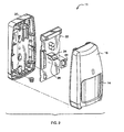
- FIG. 1 an exploded perspective view of a front assembly 10 of an intrusion sensing system 11 is shown which incorporates the invention of an insect exclusion enclosure 12 comprising means for absorbing or scattering superfluous radiation that is not focused on a detector 26.
- the insert exclusion enclosure 12 further provides a protected volume of space for optical paths between lenses 14, window 18 and a radiation detector 26 by preventing the entry of objects approximately 1 mm in diameter or larger which could interfere with the optical paths. Reducing superfluous radiation results in improved operating performance by minimizing false alarms for such an intrusion sensing system.
- a compound lens 14 attaches to the front of the insect exclusion enclosure 12 and has a plurality of lines of focus for focusing infrared radiation that enters the system onto the detector 26.
- the detector 26 is located near the focal point of the compound lens 14 and the curvilinear-shaped mirror 24.
- a window enclosure 18 provides for another source of radiation to reach the detector in addition to the compound lens 14.
- a front housing 16 encloses the compound lens 14 and the insect exclusion enclosure 12.
- FIG. 2 an exploded perspective view of a rear assembly 20 of the intrusion sensing system 11 is shown.
- a circuit board 22 having an infrared detector 26, a curvilinear-shaped mirror 24 positioned above the infrared detector 26 for reflecting radiation onto the detector 26, insect exclusion enclosure gasket 28 that fits around the perimeter of the detector 26 for interfacing with one end of the insect exclusion enclosure 12, and other circuits, is placed in the front assembly 16 and the rear assembly 20 mates with the front assembly 16 and they snap together.
- openings in the rear assembly 20 for mounting purposes which also provides a means of entry for insects.
- FIG. 3 shows a perspective view of the insect exclusion enclosure 12 having a wide front opening 30 that is adjacent to the compound lens 14 and the smaller opening 32 of the back 32 into which the curvilinear-shaped mirror 24 and infrared detector 26 protrude in the assembled system.
- FIG. 4 is a front elevational view of the insect exclusion enclosure 12 showing side walls 31 and the smaller opening 32 at the back of the enclosure 12.
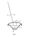
- FIG. 5 a cross-sectional view of the insect exclusion enclosure 12, compound lens 14 and infrared detector 26 is shown and an example superfluous radiation path 34 when the insect exclusion enclosure 12 does not comprise pigmentation, texturing and/or contouring. Also shown is a path 36 for beneficial or non-superfluous radiation which arrives directly at the infrared detector 26. The superfluous radiation path 34 arrives at the infrared detector 26 after repeated reflection inside the insect exclusion enclosure 12.
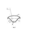
- FIG. 6 a cross-sectional view is shown of the insect exclusion enclosure 12 comprising pigmentation 40 added to the material forming the insect exclusion envelope.
- a superfluous radiation path 38 is illustrated being absorbed by a side 41 of the insect exclusion enclosure 12.
- the pigmentation 40 most effectively produces a black insect exclusion enclosure 12.
- the material used to injection mold the insect exclusion enclosure 12 is a polycarbonate plastic which may be embodied by Lexan 141 manufactured by General Electric Co., of Pittsfield, Massachusetts.
- the pigment used with the Lexan 141 comprises 0.2% carbon black of 24 nm particle size.
- FIG. 7 illustrates a cross-sectional view of the insect exclusion enclosure 12 comprising a textured surface 42.
- An example superfluous radiation path 44 strikes the textured surface 42 of the insect exclusion enclosure 12 and is scattered, so that it does not reflect and impinge upon the infrared detector 26.
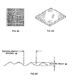
- Surface texturing is defined as the repetitive or random deviations from the normal surface which form a three-dimensional topography of the surface.
- FIG. 8A shows a typical textured surface.
- FIG. 8B is a perspective view cf a portion of the textured surface of the insect exclusion enclosure 12.
- FIG. 8C shows an enlarged cross-sectional view of the textured surface of FIGS. 8A and 8B having a texture length spacing 43 of 0.008 inches and a texture height 45 of 0.003 inches.
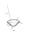
- FIG. 9 a cross-sectional view is illustrated of the insect exclusion enclosure 12 comprising contouring on the surfaces of its inner walls.
- a superfluous radiation path 48 is illustrated being attenuated by multiple lossy reflections by the sides 46 of the insect exclusion enclosure 12 by providing the contours 47 on the inner walls of the enclosure 12.
- Surface contouring 47 supersedes surface texturing as shown in FIGS. 8A and 8C when the texturing height exceeds the length of the traversing run. These dimensions cause repeated reflections within the valleys of the contouring as shown in FIG. 9, constituting repeated lossy ref lections.
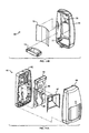
- FIG. 10A shows an exploded perspective view of an alternate embodiment of an intrusion sensing systems 50 comprising the rear assembly 20, circuit board 22 having mounted thereon the infrared detector 26 with a curvilinear-shaped mirror 24 mounted adjacent to and above the infrared detector 26, and a front assembly 16.
- FIG. 10A shows an exploded perspective view of the complete sensing system 50 comprising the rear assembly 20, circuit board 22 having mounted thereon the infrared detector 26 with a curvilinear-shaped mirror 24 mounted adjacent to and above the infrared detector 26, and a front assembly 16.
- FIG. 10B shows an exploded perspective view of the front assembly 15 comprising a front housing 16, an insect exclusion enclosure 12, a pigmented textured and/or contoured insert 52 having the general shape of the insect exclusion enclosure 12 which is placed inside the insect exclusion enclosure and the compound lens 14 which is attached to the insect exclusion enclosure 12 by engaging the lens tabs 17 over hooks 13 on the insect exclusion enclosure 12.
- a window 18 is slid onto the bottom of the insect exclusion enclosure 12.
- the insect exclusion enclosure 12 with the compound lens 14 and window 18 attached thereto and comprising the insert 52 snaps onto the rear of the front housing 16.
- the front assembly 15 then snaps into the rear assembly 20 and the insect exclusion enclosure 12 contacts the circuit board 22 via the insect exclusion enclosure gasket 28.
- This embodiment of the intrusion sensing system 50 comprises the benefits of absorbing and/or scattering of superfluous radiation by the insertion of the insert 52 into an existing intrusion sensing. system.
- FIG. 11A shows an exploded perspective view of another alternate embodiment of an intrusion system 60 comprising a rear housing 62, a circuit board 64, a superfluous radiation absorber or baffle 67 that has been pigmented, textured and/or contoured as previously described which is attached to the circuit board 64.
- the circuit board 64 is attached to the rear housing 62 and a front assembly 68 snaps together with the rear housing 62 sealing the system 60 against insect entry.
- the front assembly 68 comprises a compound lens 72 attached to the front housing 70 by means of appropriate latches 76 on the front housing 70.
- a window 74 is attached to the bottom of the front housing 70 by appropriate snap latches 77.
- This embodiment provides an intrusion sensing system 60 in which the superfluous radiation absorber does not contact the front housing 70.
- the sensing system 60 is assembled the rear housing 62 is mated with the front housing 68 and there are no openings for bug access to the inside. Also, there are no mounting holes that otherwise allow bug entry.
- the baffle 67 which is pigmented, textured and/or contoured to absorb or scatter superfluous radiation, is attached to the circuit board 64 around the perimeter of the infrared detector 65.
- the sensor system 60 When the sensor system 60 is used in an application, it may be mounted, for example, with tape means on the rear of housing 62.
Landscapes
- Physics & Mathematics (AREA)
- General Physics & Mathematics (AREA)
- Photometry And Measurement Of Optical Pulse Characteristics (AREA)
- Catching Or Destruction (AREA)
- Burglar Alarm Systems (AREA)
- Investigating Or Analysing Materials By Optical Means (AREA)
- Geophysics And Detection Of Objects (AREA)
Claims (22)
- Infrarot-Intrusionserkennungssystem (11, 50, 60), mit einem vorderen Gehäuse (16, 70), einer Verbundlinse (14, 72) zur Fokussierung von Strahlung, einem Strahlungsdetektor (26, 65), der in dem optischen Pfad der genannten Verbundlinse positioniert ist, einer gedruckten Schaltung (22, 64), welche den genannten Strahlungsdetektor und eine zugeordnete Schaltkreisanordnung trägt, und einem hinteren Gehäuse (20, 62), das mit dem genannten Gehäuse zusammenpasst und die genannte gedruckte Schaltung einschließt, wobei der genannte Strahlungsdetektor und die zugeordnete Schaltkreisanordnung auf Infrarotstrahlung ansprechen, gekennzeichnet durch:wobei das genannte Baffle ein erstes offenes Ende (30) angrenzend an die genannte Verbundlinse und ein zweites offenes Ende (32) angrenzend an den genannten Strahlungsdetektor aufweist, wobei das genannte zweite offene Ende kleiner ist als das genannte erste offene Ende;ein Baffle (12, 67), das zwischen der genannten Verbundlinse und dem genannten Strahlungsdetektor positioniert ist;
wobei das genannte Baffle so gestaltet ist, dass es Strahlung unterdrückt, die auf das genannte Baffle auftrifft. - Infrarot-Intrusionserkennungssystem nach Anspruch 1, wobei das genannte Baffle (12, 67) eine innere pigmentierte Oberfläche zum Absorbieren der genannten auftreffenden Strahlung aufweist.
- Infrarot-Intrusionserkennungssystem nach Anspruch 2, wobei die genannte innere pigmentierte Oberfläche zu dem genannten Baffle eine schwarze Farbe aufweist.
- Infrarot-Intrusionserkennungssystem nach Anspruch 1, wobei das genannte Baffle (12, 67) eine texturierte innere Oberfläche aufweist, um die genannte auftreffende Strahlung zu streuen.
- Infrarot-Intrusionserkennungssystem nach Anspruch 4, wobei die genannte texturierte Oberfläche sich wiederholende, zufällige Abweichungen von einer normalen glatten Oberfläche aufweist, so dass auf der genannten Oberfläche eine dreidimensionale Topographie gebildet wird.
- Infrarot-Intrusionserkennungssystem nach Anspruch 1, wobei das genannte Baffle (12, 67) eine profilierte Oberfläche aufweist, die dazu dient es zu verhindern, dass die genannte auftreffende Strahlung zurück auf den genannten Strahlungsdetektor reflektiert wird.
- Infrarot-Intrusionserkennungssystem nach Anspruch 6, wobei die genannte profilierte Oberfläche Gipfel und Täler aufweist, die mit Verlust behaftete Reflexionen der genannten auftreffenden Strahlung in den genannten Tälern verursachen.
- Infrarot-Intrusionserkennungssystem nach Anspruch 1, wobei das System ferner folgendes umfasst:wobei die genannte Strahlung, die durch das genannte Fenster (18, 74) in das genannte Infrarot-Intrusionserkennungssystem eintritt, auf einen Spiegel (24, 66) oberhalb des genannten Strahlungsdetektors (26, 65) auftrifft, so dass die genannte Strahlung zurück auf den genannten Strahlungsdetektor (26, 65) reflektiert wird.ein Fenster (18, 74) an einem unteren Ende des genannten vorderen Gehäuses (16, 70);
- Infrarot-Intrusionserkennungssystem nach Anspruch 1, wobei das System ferner eine Dichtung (28) umfasst, die zwischen der Oberfläche des genannten zweiten Endes des genannten Baffle (12) und der Oberfläche der genannten gedruckten Schaltung (22) positioniert ist, von wo sich der Strahlungsdetektor (26) erstreckt, so dass ein dichter Verschluss zwischen dem genannten Baffle und der genannten gedruckten Schaltung (22) erzeugt wird.
- Infrarot-Intrusionserkennungssystem nach Anspruch 1, wobei das genannte Baffle (12) an der genannten Verbundlinse (14) angebracht ist, um Insekten aus dem genannten Strahlungsdetektor (26) auszuschließen.
- Infrarot-Intrusionserkennungssystem nach Anspruch 1, wobei das genannte hintere Gehäuse (62) abdichtend mit dem genannten vorderen Gehäuse (70) zusammenpasst, um Insekten aus dem genannten Erkennungssystem (60) auszuschließen.
- Verfahren zur Unterdrückung überflüssiger Strahlung in einem Infrarot-Intrusionserkennungssystem (11, 50, 60), mit einem vorderen Gehäuse (16, 70), einer Verbundlinse (14, 72) zur Fokussierung von Strahlung, einem Strahlungsdetektor (26, 65), der in dem optischen Pfad der genannten Verbundlinse positioniert ist, einer gedruckten Schaltung (22, 64), welche den genannten Strahlungsdetektor und eine zugeordnete Schaltkreisanordnung trägt, und einem hinteren Gehäuse (20, 62), das mit dem genannten Gehäuse zusammenpasst und die genannte gedruckte Schaltung einschließt, wobei der genannte Strahlungsdetektor und die zugeordnete Schaltkreisanordnung auf Infrarotstrahlung ansprechen, gekennzeichnet durch:wobei das genannte Baffle ein erstes offenes Ende (30) angrenzend an die genannte Verbundlinse und ein zweites offenes Ende (32) angrenzend an den genannten Strahlungsdetektor aufweist, wobei das genannte zweite offene Ende kleiner ist als das genannte erste offene Ende;das Vorsehen eines Baffle (12, 67), das zwischen der genannten Verbundlinse und dem genannten Strahlungsdetektor positioniert ist;
wobei das genannte Baffle so gestaltet ist, dass es Strahlung unterdrückt, die auf das genannte Baffle auftrifft. - Verfahren nach Anspruch 12, wobei das genannte Baffle (12, 67) eine innere pigmentierte Oberfläche zum Absorbieren der genannten auftreffenden Strahlung aufweist.
- Verfahren nach Anspruch 13, wobei die genannte innere pigmentierte Oberfläche zu dem genannten Baffle eine schwarze Farbe aufweist.
- Verfahren nach Anspruch 12, wobei das genannte Baffle (12, 67) eine texturierte innere Oberfläche aufweist, um die genannte auftreffende Strahlung zu streuen.
- Verfahren nach Anspruch 15, wobei die genannte texturierte Oberfläche sich wiederholende, zufällige Abweichungen von einer normalen glatten Oberfläche aufweist, so dass auf der genannten Oberfläche eine dreidimensionale Topographie gebildet wird.
- Verfahren nach Anspruch 12, wobei das genannte Baffle (12, 67) eine profilierte Oberfläche aufweist, die dazu dient es zu verhindern, dass die genannte auftreffende Strahlung zurück auf den genannten Strahlungsdetektor reflektiert wird.
- Verfahren nach Anspruch 17, wobei die genannte profilierte Oberfläche Gipfel und Täler aufweist, die mit Verlust behaftete Reflexionen der genannten auftreffenden Strahlung in den genannten Tälern verursachen.
- Verfahren nach Anspruch 12, wobei das Verfahren ferner folgendes umfasst:wobei die genannte Strahlung, die durch das genannte Fenster (18, 74) in das genannte Infrarot-Intrusionserkennungssystem eintritt, auf einen Spiegel (24, 66) oberhalb des genannten Strahlungsdetektors (26, 65) auftrifft, so dass die genannte Strahlung zurück auf den genannten Strahlungsdetektor (26, 65) reflektiert wird.Vorsehen eines Fenster (18, 74) an einem unteren Ende des genannten vorderen Gehäuses (16, 70);
- Verfahren nach Anspruch 12, wobei das Verfahren ferner das Vorsehen einer Dichtung (28) umfasst, die zwischen der Oberfläche des genannten zweiten Endes des genannten Baffle (12) und der Oberfläche der genannten gedruckten Schaltung (22) positioniert ist, von wo sich der Strahlungsdetektor erstreckt, so dass ein dichter Verschluss zwischen dem genannten Baffle und der genannten gedruckten Schaltung (22) erzeugt wird.
- Verfahren nach Anspruch 12, wobei das genannte Baffle (12) an der genannten Verbundlinse (14) angebracht ist, um Insekten aus dem genannten Strahlungsdetektor (26) auszuschließen.
- Verfahren nach Anspruch 12, wobei das genannte hintere Gehäuse (62) abdichtend mit dem genannten vorderen Gehäuse (70) zusammenpasst, um Insekten aus dem genannten Erkennungssystem (60) auszuschließen.
Applications Claiming Priority (4)
| Application Number | Priority Date | Filing Date | Title |
|---|---|---|---|
| US47425 | 1979-06-11 | ||
| US6629097P | 1997-11-25 | 1997-11-25 | |
| US66290P | 1997-11-25 | ||
| US09/047,425 US6121876A (en) | 1998-03-24 | 1998-03-24 | System for absorbing and or scattering superfluous radiation in an optical motion sensor |
Publications (2)
| Publication Number | Publication Date |
|---|---|
| EP0919970A1 EP0919970A1 (de) | 1999-06-02 |
| EP0919970B1 true EP0919970B1 (de) | 2003-12-17 |
Family
ID=26725003
Family Applications (1)
| Application Number | Title | Priority Date | Filing Date |
|---|---|---|---|
| EP19980304694 Expired - Lifetime EP0919970B1 (de) | 1997-11-25 | 1998-06-15 | Anordnung zum Absorbieren und/oder Zerstreuen von Störlicht in einem optischen Bewegungsmelder |
Country Status (6)
| Country | Link |
|---|---|
| EP (1) | EP0919970B1 (de) |
| JP (1) | JPH11232564A (de) |
| CN (1) | CN1161725C (de) |
| AU (1) | AU744055B2 (de) |
| CA (1) | CA2236813C (de) |
| DE (1) | DE69820573T2 (de) |
Families Citing this family (7)
| Publication number | Priority date | Publication date | Assignee | Title |
|---|---|---|---|---|
| GB2345130A (en) * | 1998-12-22 | 2000-06-28 | Pyronix Ltd | Intruder sensor housing |
| KR100635843B1 (ko) * | 2000-03-16 | 2006-10-18 | 오프텍스 가부시키가이샤 | 침입검지용 센서 |
| US8232883B2 (en) * | 2009-12-04 | 2012-07-31 | Avago Technologies Ecbu Ip (Singapore) Pte. Ltd. | Optical proximity sensor with improved shield and lenses |
| CN106289536A (zh) * | 2016-10-26 | 2017-01-04 | 中国科学院云南天文台 | 一种用于光学镜面的红外测温装置 |
| CN106594538A (zh) | 2016-12-23 | 2017-04-26 | 浙江生辉照明有限公司 | 一种感应灯以及用于防止传感器模块错误触发的系统 |
| JP7155504B2 (ja) * | 2017-10-20 | 2022-10-19 | 大日本印刷株式会社 | 検知システム、波長選択素子 |
| CN114333197A (zh) * | 2021-12-30 | 2022-04-12 | 杭州海康威视数字技术股份有限公司 | 入侵探测器及入侵探测器的安装方法 |
Family Cites Families (11)
| Publication number | Priority date | Publication date | Assignee | Title |
|---|---|---|---|---|
| US4268347A (en) * | 1979-01-26 | 1981-05-19 | Exxon Research & Engineering Co. | Low reflectivity surface formed by particle track etching |
| US4271358A (en) * | 1979-11-13 | 1981-06-02 | Frank Schwarz | Selective infrared detector |
| DE3233368A1 (de) * | 1982-09-08 | 1984-03-08 | Heimann Gmbh, 6200 Wiesbaden | Strahlungsrauchmelder |
| EP0135361B1 (de) * | 1983-08-12 | 1995-04-26 | I.E.I. Pty Ltd A.C.N. 053 531 212 | Gerät zur Detektion von Partikeln in Suspension |
| JPS60185920A (ja) * | 1984-03-05 | 1985-09-21 | Matsushita Electric Ind Co Ltd | 撮像装置 |
| US4795908A (en) * | 1986-02-25 | 1989-01-03 | Masushita Electric Works, Ltd. | Infrared detector |
| NL9200283A (nl) * | 1992-02-17 | 1993-09-16 | Aritech Bv | Bewakingssysteem. |
| CH684717A5 (de) * | 1993-03-26 | 1994-11-30 | Cerberus Ag | Infraroteindringdetektor. |
| KR0151302B1 (ko) * | 1995-07-13 | 1998-12-15 | 구자홍 | 위치판별 적외선센서와 이를 이용한 센싱방법 |
| JPH09304175A (ja) * | 1996-05-20 | 1997-11-28 | Atsumi Electron Corp Ltd | ビームセンサ |
| US5790040A (en) * | 1996-12-13 | 1998-08-04 | Interactive Technologies, Inc. | Battery-operated security system sensors |
-
1998
- 1998-06-09 CA CA 2236813 patent/CA2236813C/en not_active Expired - Lifetime
- 1998-06-15 DE DE69820573T patent/DE69820573T2/de not_active Expired - Lifetime
- 1998-06-15 EP EP19980304694 patent/EP0919970B1/de not_active Expired - Lifetime
- 1998-06-23 AU AU73114/98A patent/AU744055B2/en not_active Ceased
- 1998-07-06 CN CNB981028136A patent/CN1161725C/zh not_active Expired - Lifetime
- 1998-11-06 JP JP10316585A patent/JPH11232564A/ja active Pending
Also Published As
| Publication number | Publication date |
|---|---|
| AU7311498A (en) | 1999-06-17 |
| CN1218242A (zh) | 1999-06-02 |
| JPH11232564A (ja) | 1999-08-27 |
| DE69820573D1 (de) | 2004-01-29 |
| AU744055B2 (en) | 2002-02-14 |
| DE69820573T2 (de) | 2004-09-30 |
| CN1161725C (zh) | 2004-08-11 |
| CA2236813A1 (en) | 1999-05-25 |
| EP0919970A1 (de) | 1999-06-02 |
| CA2236813C (en) | 2005-12-27 |
Similar Documents
| Publication | Publication Date | Title |
|---|---|---|
| EP1168269A3 (de) | Optoelektronische Schutzeinrichtung | |
| US5929445A (en) | Passive infrared detector | |
| US4978843A (en) | Photoelectric sensor having a folded light path | |
| EP0817148B1 (de) | Sicherheitssystem mit Lichtleitmedien | |
| JP2001229473A (ja) | 妨害検知機能付き防犯センサ | |
| EP4036884B1 (de) | Kompaktes optisches rauchmeldersystem und vorrichtung | |
| EP0919970B1 (de) | Anordnung zum Absorbieren und/oder Zerstreuen von Störlicht in einem optischen Bewegungsmelder | |
| JP4157212B2 (ja) | 光散乱式粒子検知センサ | |
| US5138302A (en) | Photoelectric, scattered light smoke detector | |
| JPH07174622A (ja) | 赤外線式人体検知装置 | |
| US6121876A (en) | System for absorbing and or scattering superfluous radiation in an optical motion sensor | |
| GB2254142A (en) | Photoelectric smoke detector | |
| US20230349807A1 (en) | Compact optical smoke detector system and apparatus | |
| GB2410085A (en) | Scattered-light fire detector for flush-mounting in a ceiling | |
| KR100349832B1 (ko) | 라인스캔형 지문입력장치 | |
| JP2002352346A (ja) | 火災感知器 | |
| CN220858263U (zh) | 遮光式感光组件和摄像模组 | |
| KR102702187B1 (ko) | 난반사 차단 기능을 갖는 cctv용 돔형 커버 | |
| JP2533687B2 (ja) | 光散乱式粒子検知センサ | |
| HK1018835A (en) | A system for absorbing and/or scattering superfluous radiation in an optical motion sensor | |
| CN220508238U (zh) | 一种成像环境状态感知装置及光学成像系统 | |
| JPS6254592B2 (de) | ||
| JP3114130B2 (ja) | 炎式火災感知器 | |
| JP2911568B2 (ja) | 熱線センサ | |
| JP4306166B2 (ja) | 球検出装置 |
Legal Events
| Date | Code | Title | Description |
|---|---|---|---|
| PUAI | Public reference made under article 153(3) epc to a published international application that has entered the european phase |
Free format text: ORIGINAL CODE: 0009012 |
|
| AK | Designated contracting states |
Kind code of ref document: A1 Designated state(s): BE CH DE DK ES FI FR GB IE IT LI NL PT SE |
|
| AX | Request for extension of the european patent |
Free format text: AL;LT;LV;MK;RO;SI |
|
| 17P | Request for examination filed |
Effective date: 19991109 |
|
| AKX | Designation fees paid |
Free format text: BE CH DE DK ES FI FR GB IE IT LI NL PT SE |
|
| 17Q | First examination report despatched |
Effective date: 20020516 |
|
| GRAH | Despatch of communication of intention to grant a patent |
Free format text: ORIGINAL CODE: EPIDOS IGRA |
|
| GRAS | Grant fee paid |
Free format text: ORIGINAL CODE: EPIDOSNIGR3 |
|
| GRAL | Information related to payment of fee for publishing/printing deleted |
Free format text: ORIGINAL CODE: EPIDOSDIGR3 |
|
| GRAS | Grant fee paid |
Free format text: ORIGINAL CODE: EPIDOSNIGR3 |
|
| GRAA | (expected) grant |
Free format text: ORIGINAL CODE: 0009210 |
|
| RAP1 | Party data changed (applicant data changed or rights of an application transferred) |
Owner name: HONEYWELL, INC |
|
| AK | Designated contracting states |
Kind code of ref document: B1 Designated state(s): BE CH DE DK ES FI FR GB IE IT LI NL PT SE |
|
| PG25 | Lapsed in a contracting state [announced via postgrant information from national office to epo] |
Ref country code: NL Free format text: LAPSE BECAUSE OF FAILURE TO SUBMIT A TRANSLATION OF THE DESCRIPTION OR TO PAY THE FEE WITHIN THE PRESCRIBED TIME-LIMIT Effective date: 20031217 Ref country code: LI Free format text: LAPSE BECAUSE OF FAILURE TO SUBMIT A TRANSLATION OF THE DESCRIPTION OR TO PAY THE FEE WITHIN THE PRESCRIBED TIME-LIMIT Effective date: 20031217 Ref country code: IT Free format text: LAPSE BECAUSE OF FAILURE TO SUBMIT A TRANSLATION OF THE DESCRIPTION OR TO PAY THE FEE WITHIN THE PRESCRIBED TIME-LIMIT;WARNING: LAPSES OF ITALIAN PATENTS WITH EFFECTIVE DATE BEFORE 2007 MAY HAVE OCCURRED AT ANY TIME BEFORE 2007. THE CORRECT EFFECTIVE DATE MAY BE DIFFERENT FROM THE ONE RECORDED. Effective date: 20031217 Ref country code: FR Free format text: LAPSE BECAUSE OF FAILURE TO SUBMIT A TRANSLATION OF THE DESCRIPTION OR TO PAY THE FEE WITHIN THE PRESCRIBED TIME-LIMIT Effective date: 20031217 Ref country code: FI Free format text: LAPSE BECAUSE OF FAILURE TO SUBMIT A TRANSLATION OF THE DESCRIPTION OR TO PAY THE FEE WITHIN THE PRESCRIBED TIME-LIMIT Effective date: 20031217 Ref country code: CH Free format text: LAPSE BECAUSE OF FAILURE TO SUBMIT A TRANSLATION OF THE DESCRIPTION OR TO PAY THE FEE WITHIN THE PRESCRIBED TIME-LIMIT Effective date: 20031217 Ref country code: BE Free format text: LAPSE BECAUSE OF FAILURE TO SUBMIT A TRANSLATION OF THE DESCRIPTION OR TO PAY THE FEE WITHIN THE PRESCRIBED TIME-LIMIT Effective date: 20031217 |
|
| REG | Reference to a national code |
Ref country code: GB Ref legal event code: FG4D |
|
| REG | Reference to a national code |
Ref country code: CH Ref legal event code: EP |
|
| REG | Reference to a national code |
Ref country code: IE Ref legal event code: FG4D |
|
| REF | Corresponds to: |
Ref document number: 69820573 Country of ref document: DE Date of ref document: 20040129 Kind code of ref document: P |
|
| PG25 | Lapsed in a contracting state [announced via postgrant information from national office to epo] |
Ref country code: SE Free format text: LAPSE BECAUSE OF FAILURE TO SUBMIT A TRANSLATION OF THE DESCRIPTION OR TO PAY THE FEE WITHIN THE PRESCRIBED TIME-LIMIT Effective date: 20040317 Ref country code: DK Free format text: LAPSE BECAUSE OF FAILURE TO SUBMIT A TRANSLATION OF THE DESCRIPTION OR TO PAY THE FEE WITHIN THE PRESCRIBED TIME-LIMIT Effective date: 20040317 |
|
| PG25 | Lapsed in a contracting state [announced via postgrant information from national office to epo] |
Ref country code: ES Free format text: LAPSE BECAUSE OF FAILURE TO SUBMIT A TRANSLATION OF THE DESCRIPTION OR TO PAY THE FEE WITHIN THE PRESCRIBED TIME-LIMIT Effective date: 20040328 |
|
| NLV1 | Nl: lapsed or annulled due to failure to fulfill the requirements of art. 29p and 29m of the patents act | ||
| PG25 | Lapsed in a contracting state [announced via postgrant information from national office to epo] |
Ref country code: IE Free format text: LAPSE BECAUSE OF NON-PAYMENT OF DUE FEES Effective date: 20040615 |
|
| REG | Reference to a national code |
Ref country code: CH Ref legal event code: PL |
|
| PLBE | No opposition filed within time limit |
Free format text: ORIGINAL CODE: 0009261 |
|
| STAA | Information on the status of an ep patent application or granted ep patent |
Free format text: STATUS: NO OPPOSITION FILED WITHIN TIME LIMIT |
|
| 26N | No opposition filed |
Effective date: 20040920 |
|
| EN | Fr: translation not filed | ||
| REG | Reference to a national code |
Ref country code: IE Ref legal event code: MM4A |
|
| PG25 | Lapsed in a contracting state [announced via postgrant information from national office to epo] |
Ref country code: PT Free format text: LAPSE BECAUSE OF NON-PAYMENT OF DUE FEES Effective date: 20040517 |
|
| PGFP | Annual fee paid to national office [announced via postgrant information from national office to epo] |
Ref country code: GB Payment date: 20170526 Year of fee payment: 20 |
|
| PGFP | Annual fee paid to national office [announced via postgrant information from national office to epo] |
Ref country code: DE Payment date: 20170623 Year of fee payment: 20 |
|
| REG | Reference to a national code |
Ref country code: DE Ref legal event code: R071 Ref document number: 69820573 Country of ref document: DE |
|
| REG | Reference to a national code |
Ref country code: GB Ref legal event code: PE20 Expiry date: 20180614 |
|
| PG25 | Lapsed in a contracting state [announced via postgrant information from national office to epo] |
Ref country code: GB Free format text: LAPSE BECAUSE OF EXPIRATION OF PROTECTION Effective date: 20180614 |