EP0919987A2 - Ultrasonic probe assembly with comb-shaped array - Google Patents
Ultrasonic probe assembly with comb-shaped array Download PDFInfo
- Publication number
- EP0919987A2 EP0919987A2 EP19980630065 EP98630065A EP0919987A2 EP 0919987 A2 EP0919987 A2 EP 0919987A2 EP 19980630065 EP19980630065 EP 19980630065 EP 98630065 A EP98630065 A EP 98630065A EP 0919987 A2 EP0919987 A2 EP 0919987A2
- Authority
- EP
- European Patent Office
- Prior art keywords
- ultrasonic
- supports
- heads
- probe
- spacers
- Prior art date
- Legal status (The legal status is an assumption and is not a legal conclusion. Google has not performed a legal analysis and makes no representation as to the accuracy of the status listed.)
- Pending
Links
- 239000000523 sample Substances 0.000 title claims abstract description 90
- 125000006850 spacer group Chemical group 0.000 claims description 26
- 238000000034 method Methods 0.000 claims description 12
- 238000012360 testing method Methods 0.000 claims description 7
- 239000000463 material Substances 0.000 description 11
- 239000004020 conductor Substances 0.000 description 5
- 239000002131 composite material Substances 0.000 description 3
- 238000010276 construction Methods 0.000 description 3
- 230000008878 coupling Effects 0.000 description 3
- 238000010168 coupling process Methods 0.000 description 3
- 238000005859 coupling reaction Methods 0.000 description 3
- 239000008393 encapsulating agent Substances 0.000 description 3
- 238000007689 inspection Methods 0.000 description 3
- 229920000642 polymer Polymers 0.000 description 3
- 230000008646 thermal stress Effects 0.000 description 3
- RYGMFSIKBFXOCR-UHFFFAOYSA-N Copper Chemical compound [Cu] RYGMFSIKBFXOCR-UHFFFAOYSA-N 0.000 description 2
- 239000004593 Epoxy Substances 0.000 description 2
- XAGFODPZIPBFFR-UHFFFAOYSA-N aluminium Chemical compound [Al] XAGFODPZIPBFFR-UHFFFAOYSA-N 0.000 description 2
- 229910052782 aluminium Inorganic materials 0.000 description 2
- 238000003491 array Methods 0.000 description 2
- 239000003054 catalyst Substances 0.000 description 2
- 229910052802 copper Inorganic materials 0.000 description 2
- 239000010949 copper Substances 0.000 description 2
- 238000013016 damping Methods 0.000 description 2
- 230000007547 defect Effects 0.000 description 2
- 239000003822 epoxy resin Substances 0.000 description 2
- 229910052451 lead zirconate titanate Inorganic materials 0.000 description 2
- 229920000647 polyepoxide Polymers 0.000 description 2
- 239000004677 Nylon Substances 0.000 description 1
- 238000005452 bending Methods 0.000 description 1
- 238000005253 cladding Methods 0.000 description 1
- 238000013461 design Methods 0.000 description 1
- 230000008030 elimination Effects 0.000 description 1
- 238000003379 elimination reaction Methods 0.000 description 1
- 238000011156 evaluation Methods 0.000 description 1
- 239000011152 fibreglass Substances 0.000 description 1
- 238000011065 in-situ storage Methods 0.000 description 1
- HFGPZNIAWCZYJU-UHFFFAOYSA-N lead zirconate titanate Chemical compound [O-2].[O-2].[O-2].[O-2].[O-2].[Ti+4].[Zr+4].[Pb+2] HFGPZNIAWCZYJU-UHFFFAOYSA-N 0.000 description 1
- 238000012544 monitoring process Methods 0.000 description 1
- 229920001778 nylon Polymers 0.000 description 1
- 238000013021 overheating Methods 0.000 description 1
- 238000011160 research Methods 0.000 description 1
- 230000035945 sensitivity Effects 0.000 description 1
- 238000004154 testing of material Methods 0.000 description 1
- 238000002604 ultrasonography Methods 0.000 description 1
Images

Classifications
-
- G—PHYSICS
- G10—MUSICAL INSTRUMENTS; ACOUSTICS
- G10K—SOUND-PRODUCING DEVICES; METHODS OR DEVICES FOR PROTECTING AGAINST, OR FOR DAMPING, NOISE OR OTHER ACOUSTIC WAVES IN GENERAL; ACOUSTICS NOT OTHERWISE PROVIDED FOR
- G10K11/00—Methods or devices for transmitting, conducting or directing sound in general; Methods or devices for protecting against, or for damping, noise or other acoustic waves in general
- G10K11/004—Mounting transducers, e.g. provided with mechanical moving or orienting device
-
- B—PERFORMING OPERATIONS; TRANSPORTING
- B06—GENERATING OR TRANSMITTING MECHANICAL VIBRATIONS IN GENERAL
- B06B—METHODS OR APPARATUS FOR GENERATING OR TRANSMITTING MECHANICAL VIBRATIONS OF INFRASONIC, SONIC, OR ULTRASONIC FREQUENCY, e.g. FOR PERFORMING MECHANICAL WORK IN GENERAL
- B06B1/00—Methods or apparatus for generating mechanical vibrations of infrasonic, sonic, or ultrasonic frequency
- B06B1/02—Methods or apparatus for generating mechanical vibrations of infrasonic, sonic, or ultrasonic frequency making use of electrical energy
- B06B1/06—Methods or apparatus for generating mechanical vibrations of infrasonic, sonic, or ultrasonic frequency making use of electrical energy operating with piezoelectric effect or with electrostriction
- B06B1/0607—Methods or apparatus for generating mechanical vibrations of infrasonic, sonic, or ultrasonic frequency making use of electrical energy operating with piezoelectric effect or with electrostriction using multiple elements
-
- G—PHYSICS
- G01—MEASURING; TESTING
- G01H—MEASUREMENT OF MECHANICAL VIBRATIONS OR ULTRASONIC, SONIC OR INFRASONIC WAVES
- G01H1/00—Measuring characteristics of vibrations in solids by using direct conduction to the detector
Definitions
- This invention relates to the ultrasonic testing of materials, and in particular to an ultrasonic comb probe array assembly for generating ultrasonic waves in an object.
- Ultrasound is commonly used to locate discontinuities and other imperfections in materials and to characterize materials and measure distances.
- Conventional ultrasonic testing employs longitudinal or shear waves in a point by point inspection of the object.
- ultrasonic guided wave techniques have been developed. See, generally Rose, Rajana, and Carr, Ultrasonic Guided Wave Inspection Concepts for Steam Generator Tubing, Materials Evaluation , February 1993, Page 307, incorporated herein by reference.
- These ultrasonic guided wave techniques involve launching ultrasonic waves at one position on an object, which propagate for substantial distances within the object, "guided" by the boundaries of the object. Defects in the object reflect the guided waves, and thus can be identified and located by monitoring the received waves.
- Ultrasonic guided wave techniques offer several advantages over other ultrasonic inspection techniques, including the ability to simultaneously inspect the entire cross-section and length of an object; the elimination of complicated and expensive apparatus for positioning and indexing conventional ultrasonic probes; and increased sensitivity to some types of defects.
- the design parameters for ultrasonic comb probes include factors such as size, shape, frequency, frequency band width, and coupling means.
- the probes currently in use are designed and built for particular applications. They are typically two pieces secured over the object, each piece having a plurality of ultrasonic transducers secured therein.
- One difficultly encountered with the comb probes presently available is that they are fragile and prone to failure. High energies used in some applications and the inefficiencies in the piezoelectric materials used in the transducers may cause some of this energy to be dissipated as heat. This heat can causes thermal stresses in the probe which can lead to failure of the ultrasonic transducer elements. Failure of a single element in conventional probes requires replacement of the entire probe.
- probe arrays are constructed for particular modes of operation.
- available construction techniques require that a different probe array be used for each different guided wave mode.
- Still another difficulty encountered with presently available comb probes is coupling to objects whose surfaces are not perfectly smooth. Because of the rigidity of presently available arrays, if one element contacts a high point on the surface of the object, there will be a gap between the other elements and the surface. While in some cases these gaps can be bridged with a couplant, direct contact between the transducer and the object is preferable.
- the present invention provides an ultrasonic probe array assembly that is of simple, yet robust construction; that resists overheating of the transducers; that allows for replacement of failed transducers; that allows the spacing between the transducers to be changed; and which allows better coupling between the individual transducers and the surface of the object.
- the array assembly of the present invention comprises a plurality of probe heads, each probe head comprising first and second supports. There is a transducer mounted on each support.
- the supports are hingedly connected to allow relative pivoting movement of the first and second supports in a plane.
- the probe heads are connected together in a parallel, spaced relation, with their hinged connections generally aligned.
- the probe heads are preferably separated by replaceable spacers, so that spacing between the probe heads can be changed.
- This construction allows the individual probe heads to be replaced, and allows the spacing of the heads to be changed to generate different guided wave modes.
- the use of separate probe heads and spacers also reduces heat build up, reducing the risk of heat damage to the transducers and damage to the array assembly from thermal stresses.
- the array assembly of the present invention is mounted on the test object with the individual probe heads of the array assembly each surrounding a portion of the object. These individual probe heads better accommodate variations in the surface of the test object, achieving better contact between the transducers and the object.
- the array assembly of the present invention thus provides a simple yet robust apparatus for the ultrasonic guided wave testing of objects.
- the apparatus is resistant to heat damage and thermal stresses, it allows failed transducers to be easily replaced, it permits adjustment of the spacing between the transducers, and it achieves better contact between the transducers and the surface of the test object.
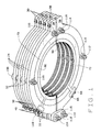
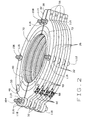
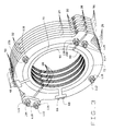
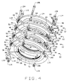
- a comb probe array assembly constructed according to the principles of this invention is indicated generally as 20 in the Figs 1-4.
- the assembly 20 comprises a plurality of probe heads 22.
- Each probe head 22 comprises first and second supports 24 and 26.
- the first and second supports 24 and 26 are hingedly connected at one end for relative pivotal movement in a plane.
- Each of the first and second supports includes a transducer 28.
- Fasteners 30 between the first and second supports can secure the supports around an object and hold their respective transducers 28 in intimate contact with the surface of an object.
- the probe heads 22 are arranged in a stack in parallel, spaced relationship, with the hinged connections generally aligned. There are preferably spacers 32 between adjacent probe heads 22. These spacers are preferably replaceable, as described below, so that the spacing of the probe heads 22, and more particularly the spacing of the transducers 28 on the probe heads, can be changed.
- the first support 24 comprises a generally semicircular housing 34 having tabs 36 and 38 projecting from the front and rear ends of the body, and a semicircular recess 40 in one face, adjacent the inner circumference of the semicircular housing.
- the housing 34 is preferably made of aluminum, which is rigid and light weight, yet easy to machine.
- the bottom of the stem of the "T" communicates with the semicircular recess 40.
- Two radial passages extend from the outer circumference of the semicircular housing 34 to the top of the "T". Connectors 48 and 50 are mounted in these passages for making electrical connections with the probe head as described below.
- the seccnd support 26 comprises a generally semicircular housing 52 having tabs 54 and 56 projecting from the front and rear ends of the housing, and a semicircular recess 58 in one face, adjacent the inner circumference of the semicircular housing.
- the housing 52 like housing 34, is preferably made of aluminum.
- the bottom of the stem of the "T" communicates with the semicircular recess 58.
- Two radial passages 62 and 64 extend from the outer circumference of the semicircular body to the top of the "T". Connectcrs 66 and 68 are mounted in these passages for making electrical connections with the probe head as described below.
- Semicircular bodies 70 and 72 of an acoustic damping material are seated in the recess 40 and 58 in the first and second housings 34 and 52.
- the acoustic damping material is preferably an epoxy or epoxy composite, such as epoxy resin 2057 and catalyst 9 available from Grace Specialty Polymer, 55 Hayden Avenue, Lexington, MA 02173.
- the body 70 has a semicircular groove 74 on one face, adjacent its inner edge, and a radially extending groove 76 extending from its outer edge to the semicircular groove, that aligns with the T-shaped cutout 42.
- the body 72 has a semicircular groove 78 on one face, adjacent its inner edge, and a radially extending groove 80 extending from its outer edge to the semicircular groove, that aligns with the T-shaped cutout 60.
- the transducers 28 are preferably semicircular strips 82 and 84 of a piezoelectric material electrically connected to semicircular conductors 86 and 88, respectively.
- the piezoelectric material is preferably a PZT (lead zirconate titanate, such as those disclosed in The Application of 1-3 Piezocomposites in Acoustic Transducers, Wallace Arden Smith, Materials Division, Code 1131, Office of Naval Research, Arlington, Virginia 22217-5000, incorporated herein by reference. This composite may be cut into a strip and formed into a semicircular configuration by scoring and bending, or the composite may be sufficiently bendable.
- the conductors 86 and 88 are preferably semicircular pieces of conventional fiberglass circuit board material with copper clad conductor strips. Wires (not shown) soldered to the copper cladding and to the piezoelectric material electrically connect the conductors 86 and 88 to their respective piezoelectric strips 82 and 84.
- the piezoelectric strips 82 and 84 and their associated conductors 86 and 88 fit within the grooves 74 and 78 in the bodies 70 and 72, respectively.
- the transducers 28 are secured in their respective supports with a polymer encapsulant 90 formed in situ.
- the encapsulant may be an epoxy resin 2057 and catalyst 9 available from Grace Specialty Polymers, 55 Hayden Ave., Lexington, MA 02173. After setting the encapsulant can be machined to have smooth surfaces even with the surface of the housing.
- the first supports 24 each have three holes 92, 94, and 96 therein.
- the hole 92 is located in the tab 36
- the hole 94 is located generally in the center of the arc of the housing 34
- the hole 96 is located generally in the tab 38.
- the second supports 26 each have three holes 98, 100, and 102 therein.
- the hole 98 is located in the tab 54
- the hole 100 is located generally in the center of the arc of the housing 52
- the hole 90 is located generally in the tab 56.
- the probe heads 22 are arranged in parallel, spaced apart relation.
- Bolt 104 extends through the aligned holes 92
- bolt 106 extends through the aligned holes 94
- bolt 108 extends through the aligned holes 96 in the first support 24.
- Bolt 110 extends through the aligned holes 98
- bolt 112 extends through the aligned holes 100
- bolt 114 extends through the aligned holes 102, in the second support 26.
- Nuts 116 on the ends of the bolts 104, 106, and 108 hold the supports 24 and spacers 32 together.
- nuts 116 on the ends of the bolts 110, 112, and 114 hold the supports 26 and spacers 32 together.
- the spacers are preferably made of nylon.
- the bolts 104 and 110 extend through links 118 which hold the bolts together, thereby hingedly connecting the first supports 24 on bolt 104 with the second supports 26 on bolt 110.
- a fastener 30 extends between the tabs 38 on the first supports 24 and the tab 56 of the respective second supports 26 to secure the supports around the object, and hold the transducers 28 in contact with the surface of the object.
- a comb probe array assembly is assembled from a plurality of probe heads 22 and spacers 32 selected to achieve the appropriate transducer spacing for the intended guided wave mode.
- the connectors 48 and 50 on the first supports 24 and the connectors 66 and 68 on the second supports 26 are daisy chained together.
- the array assembly 20 is secured on the inspected part by securing the individual probe heads 22 around the inspected part with fasteners 30. There is enough freedom in the assembly to allow the first and second supports 24 and 26 of each probe head 22 to fit closely against the surface of the pipe, holding their respective transducers 28 in close proximity to the surface of the pipe.
Landscapes
- Engineering & Computer Science (AREA)
- Physics & Mathematics (AREA)
- Mechanical Engineering (AREA)
- General Physics & Mathematics (AREA)
- Acoustics & Sound (AREA)
- Multimedia (AREA)
- Investigating Or Analyzing Materials By The Use Of Ultrasonic Waves (AREA)
- Transducers For Ultrasonic Waves (AREA)
Applications Claiming Priority (2)
| Application Number | Priority Date | Filing Date | Title |
|---|---|---|---|
| US97946197A | 1997-11-26 | 1997-11-26 | |
| US979461 | 1997-11-26 |
Publications (1)
| Publication Number | Publication Date |
|---|---|
| EP0919987A2 true EP0919987A2 (en) | 1999-06-02 |
Family
ID=25526902
Family Applications (1)
| Application Number | Title | Priority Date | Filing Date |
|---|---|---|---|
| EP19980630065 Pending EP0919987A2 (en) | 1997-11-26 | 1998-11-06 | Ultrasonic probe assembly with comb-shaped array |
Country Status (5)
| Country | Link |
|---|---|
| EP (1) | EP0919987A2 (ja) |
| JP (1) | JPH11242019A (ja) |
| CN (1) | CN1232180A (ja) |
| CA (1) | CA2250534A1 (ja) |
| TW (1) | TW373066B (ja) |
Cited By (3)
| Publication number | Priority date | Publication date | Assignee | Title |
|---|---|---|---|---|
| US8043221B2 (en) | 2007-08-17 | 2011-10-25 | General Electric Company | Multi-headed imaging probe and imaging system using same |
| US9532768B2 (en) | 2007-08-17 | 2017-01-03 | General Electric Company | Multi-headed imaging probe and imaging system using same |
| WO2022242798A1 (de) * | 2021-05-18 | 2022-11-24 | Physik Instrumente (Pi) Gmbh & Co. Kg | Positioniervorrichtung und verfahren zum betreiben einer solchen positioniervorrichtung |
Families Citing this family (7)
| Publication number | Priority date | Publication date | Assignee | Title |
|---|---|---|---|---|
| KR100691164B1 (ko) * | 2005-08-02 | 2007-03-09 | 주식회사 파이컴 | 프로브 카드 조립체 |
| CN103743824B (zh) * | 2014-01-14 | 2015-12-30 | 国家电网公司 | 用于砼杆焊缝超声波检测的环形固定器工具 |
| CN104062360B (zh) * | 2014-07-11 | 2016-08-17 | 云南大学 | 三频双斜探头超声植物茎干成分检测装置 |
| CN104749258B (zh) * | 2015-03-19 | 2017-05-31 | 暨南大学 | 用于管件检测的超声导波探头阵列固定装置 |
| CN109342566B (zh) * | 2018-11-22 | 2023-09-22 | 江苏方天电力技术有限公司 | 一种基于超声导波的盆式绝缘子缺陷检测定位装置及方法 |
| CN110487155B (zh) * | 2019-08-02 | 2021-04-06 | 西安工业大学 | 线阵测头及接触式直齿圆柱齿轮齿面点云的获取方法 |
| CN113820396B (zh) * | 2021-09-16 | 2024-03-22 | 哈尔滨工程大学 | 一种密集阵列管道中管道相贯面的缺陷检测设备 |
-
1998
- 1998-10-30 CA CA 2250534 patent/CA2250534A1/en not_active Abandoned
- 1998-11-06 EP EP19980630065 patent/EP0919987A2/en active Pending
- 1998-11-12 JP JP32121698A patent/JPH11242019A/ja active Pending
- 1998-11-23 CN CN 98122623 patent/CN1232180A/zh active Pending
- 1998-11-25 TW TW087119553A patent/TW373066B/zh active
Cited By (3)
| Publication number | Priority date | Publication date | Assignee | Title |
|---|---|---|---|---|
| US8043221B2 (en) | 2007-08-17 | 2011-10-25 | General Electric Company | Multi-headed imaging probe and imaging system using same |
| US9532768B2 (en) | 2007-08-17 | 2017-01-03 | General Electric Company | Multi-headed imaging probe and imaging system using same |
| WO2022242798A1 (de) * | 2021-05-18 | 2022-11-24 | Physik Instrumente (Pi) Gmbh & Co. Kg | Positioniervorrichtung und verfahren zum betreiben einer solchen positioniervorrichtung |
Also Published As
| Publication number | Publication date |
|---|---|
| CA2250534A1 (en) | 1999-05-26 |
| TW373066B (en) | 1999-11-01 |
| CN1232180A (zh) | 1999-10-20 |
| JPH11242019A (ja) | 1999-09-07 |
Similar Documents
| Publication | Publication Date | Title |
|---|---|---|
| EP2133691B1 (en) | High resolution and flexible eddy current array probe | |
| EP0919987A2 (en) | Ultrasonic probe assembly with comb-shaped array | |
| KR100299277B1 (ko) | 초음파변환기어레이및그제조방법 | |
| US5829148A (en) | Spatial measuring device | |
| US8033181B2 (en) | Probe for fastener identification and ultrasonic load measurement | |
| US3955740A (en) | Vibratory seam welding apparatus | |
| US6546803B1 (en) | Ultrasonic array transducer | |
| US20080312846A1 (en) | Sensor Infrastructure | |
| EP0037620A1 (en) | Acoustic impedance matching device | |
| EP0815955B1 (en) | Support unit for ultrasonic vibration resonator | |
| JP2002538436A (ja) | 腐食にさらされる物体の電位をモニタするためのセンサ装置 | |
| US6007490A (en) | Ultrasonic probe with disconnectable transducer | |
| US5189915A (en) | Single mode ultrasonic inspection method and apparatus | |
| ES2087805T3 (es) | Sonda ultrasonica y procedimiento para su funcionamiento. | |
| US20090071254A1 (en) | Method and apparatus for the detection of cracks in the teeth of generator rotors | |
| Savoia et al. | A low frequency broadband flextensional ultrasonic transducer array | |
| JPH06502813A (ja) | マルチチャンネルアレイ・パルス滴付着装置の試験方法 | |
| MXPA98009887A (en) | Assembly of provision of probe of peine ultrason | |
| CN114280585A (zh) | 高频宽带多波束接收阵及其制作方法 | |
| JP4412281B2 (ja) | 超音波探触子 | |
| WO2008057109A1 (en) | Cable direct interconnection method for array transducers | |
| JPH0349389B2 (ja) | ||
| JP3772601B2 (ja) | 超音波発生装置 | |
| US20090183350A1 (en) | Method for Ultrasound Probe Repair | |
| WO2013191847A1 (en) | Ultrasonic testing device and method of assembly |
Legal Events
| Date | Code | Title | Description |
|---|---|---|---|
| PUAI | Public reference made under article 153(3) epc to a published international application that has entered the european phase |
Free format text: ORIGINAL CODE: 0009012 |
|
| AK | Designated contracting states |
Kind code of ref document: A2 Designated state(s): AT BE CH CY DE DK ES FI FR GB GR IE IT LI LU MC NL PT SE |
|
| AX | Request for extension of the european patent |
Free format text: AL;LT;LV;MK;RO;SI |
|
| STAA | Information on the status of an ep patent application or granted ep patent |
Free format text: STATUS: THE APPLICATION HAS BEEN WITHDRAWN |
|
| 18W | Application withdrawn |
Withdrawal date: 20000216 |
|
| R18W | Application withdrawn (corrected) |
Effective date: 20000210 |
|
| D18W | Application withdrawn (deleted) | ||
| R18W | Application withdrawn (corrected) |
Effective date: 20000210 |