EP0920064A1 - Brennstoffzellensystem mit einem durch eine Verbrennungseinrichtung geheizten Reformierungsreaktor - Google Patents
Brennstoffzellensystem mit einem durch eine Verbrennungseinrichtung geheizten Reformierungsreaktor Download PDFInfo
- Publication number
- EP0920064A1 EP0920064A1 EP98202192A EP98202192A EP0920064A1 EP 0920064 A1 EP0920064 A1 EP 0920064A1 EP 98202192 A EP98202192 A EP 98202192A EP 98202192 A EP98202192 A EP 98202192A EP 0920064 A1 EP0920064 A1 EP 0920064A1
- Authority
- EP
- European Patent Office
- Prior art keywords
- combustor
- fuel
- effluent
- exhaust
- input end
- Prior art date
- Legal status (The legal status is an assumption and is not a legal conclusion. Google has not performed a legal analysis and makes no representation as to the accuracy of the status listed.)
- Withdrawn
Links
Images

Classifications
-
- C—CHEMISTRY; METALLURGY
- C01—INORGANIC CHEMISTRY
- C01B—NON-METALLIC ELEMENTS; COMPOUNDS THEREOF; METALLOIDS OR COMPOUNDS THEREOF NOT COVERED BY SUBCLASS C01C
- C01B3/00—Hydrogen; Gaseous mixtures containing hydrogen; Separation of hydrogen from mixtures containing it; Purification of hydrogen; Reversible storage of hydrogen
- C01B3/02—Production of hydrogen; Production of gaseous mixtures containing hydrogen
- C01B3/32—Production of hydrogen; Production of gaseous mixtures containing hydrogen by reaction of gaseous or liquid organic compounds with gasifying agents, e.g. water, carbon dioxide or air
- C01B3/34—Production of hydrogen; Production of gaseous mixtures containing hydrogen by reaction of gaseous or liquid organic compounds with gasifying agents, e.g. water, carbon dioxide or air by reaction of hydrocarbons with gasifying agents
- C01B3/48—Production of hydrogen; Production of gaseous mixtures containing hydrogen by reaction of gaseous or liquid organic compounds with gasifying agents, e.g. water, carbon dioxide or air by reaction of hydrocarbons with gasifying agents followed by reaction of water vapour with carbon monoxide
-
- B—PERFORMING OPERATIONS; TRANSPORTING
- B01—PHYSICAL OR CHEMICAL PROCESSES OR APPARATUS IN GENERAL
- B01J—CHEMICAL OR PHYSICAL PROCESSES, e.g. CATALYSIS OR COLLOID CHEMISTRY; THEIR RELEVANT APPARATUS
- B01J19/00—Chemical, physical or physico-chemical processes in general; Their relevant apparatus
- B01J19/24—Stationary reactors without moving elements inside
- B01J19/2415—Tubular reactors
- B01J19/243—Tubular reactors spirally, concentrically or zigzag wound
-
- B—PERFORMING OPERATIONS; TRANSPORTING
- B01—PHYSICAL OR CHEMICAL PROCESSES OR APPARATUS IN GENERAL
- B01J—CHEMICAL OR PHYSICAL PROCESSES, e.g. CATALYSIS OR COLLOID CHEMISTRY; THEIR RELEVANT APPARATUS
- B01J8/00—Chemical or physical processes in general, conducted in the presence of fluids and solid particles; Apparatus for such processes
- B01J8/02—Chemical or physical processes in general, conducted in the presence of fluids and solid particles; Apparatus for such processes with stationary particles, e.g. in fixed beds
- B01J8/04—Chemical or physical processes in general, conducted in the presence of fluids and solid particles; Apparatus for such processes with stationary particles, e.g. in fixed beds the fluid passing successively through two or more beds
- B01J8/0403—Chemical or physical processes in general, conducted in the presence of fluids and solid particles; Apparatus for such processes with stationary particles, e.g. in fixed beds the fluid passing successively through two or more beds the fluid flow within the beds being predominantly horizontal
- B01J8/0423—Chemical or physical processes in general, conducted in the presence of fluids and solid particles; Apparatus for such processes with stationary particles, e.g. in fixed beds the fluid passing successively through two or more beds the fluid flow within the beds being predominantly horizontal through two or more otherwise shaped beds
- B01J8/0438—Chemical or physical processes in general, conducted in the presence of fluids and solid particles; Apparatus for such processes with stationary particles, e.g. in fixed beds the fluid passing successively through two or more beds the fluid flow within the beds being predominantly horizontal through two or more otherwise shaped beds the beds being placed next to each other
-
- C—CHEMISTRY; METALLURGY
- C01—INORGANIC CHEMISTRY
- C01B—NON-METALLIC ELEMENTS; COMPOUNDS THEREOF; METALLOIDS OR COMPOUNDS THEREOF NOT COVERED BY SUBCLASS C01C
- C01B3/00—Hydrogen; Gaseous mixtures containing hydrogen; Separation of hydrogen from mixtures containing it; Purification of hydrogen; Reversible storage of hydrogen
- C01B3/02—Production of hydrogen; Production of gaseous mixtures containing hydrogen
- C01B3/32—Production of hydrogen; Production of gaseous mixtures containing hydrogen by reaction of gaseous or liquid organic compounds with gasifying agents, e.g. water, carbon dioxide or air
- C01B3/323—Catalytic reaction of gaseous or liquid organic compounds other than hydrocarbons with gasifying agents
-
- C—CHEMISTRY; METALLURGY
- C01—INORGANIC CHEMISTRY
- C01B—NON-METALLIC ELEMENTS; COMPOUNDS THEREOF; METALLOIDS OR COMPOUNDS THEREOF NOT COVERED BY SUBCLASS C01C
- C01B3/00—Hydrogen; Gaseous mixtures containing hydrogen; Separation of hydrogen from mixtures containing it; Purification of hydrogen; Reversible storage of hydrogen
- C01B3/50—Separation of hydrogen or hydrogen-containing gases from gaseous mixtures, e.g. purification
- C01B3/56—Separation of hydrogen or hydrogen-containing gases from gaseous mixtures, e.g. purification by contacting with solids; Regeneration of used solids
- C01B3/58—Separation of hydrogen or hydrogen-containing gases from gaseous mixtures, e.g. purification by contacting with solids; Regeneration of used solids including a catalytic reaction
- C01B3/583—Separation of hydrogen or hydrogen-containing gases from gaseous mixtures, e.g. purification by contacting with solids; Regeneration of used solids including a catalytic reaction the reaction being the selective oxidation of carbon monoxide
-
- H—ELECTRICITY
- H01—ELECTRIC ELEMENTS
- H01M—PROCESSES OR MEANS, e.g. BATTERIES, FOR THE DIRECT CONVERSION OF CHEMICAL ENERGY INTO ELECTRICAL ENERGY
- H01M8/00—Fuel cells; Manufacture thereof
- H01M8/04—Auxiliary arrangements, e.g. for control of pressure or for circulation of fluids
- H01M8/04223—Auxiliary arrangements, e.g. for control of pressure or for circulation of fluids during start-up or shut-down; Depolarisation or activation, e.g. purging; Means for short-circuiting defective fuel cells
- H01M8/04225—Auxiliary arrangements, e.g. for control of pressure or for circulation of fluids during start-up or shut-down; Depolarisation or activation, e.g. purging; Means for short-circuiting defective fuel cells during start-up
-
- H—ELECTRICITY
- H01—ELECTRIC ELEMENTS
- H01M—PROCESSES OR MEANS, e.g. BATTERIES, FOR THE DIRECT CONVERSION OF CHEMICAL ENERGY INTO ELECTRICAL ENERGY
- H01M8/00—Fuel cells; Manufacture thereof
- H01M8/06—Combination of fuel cells with means for production of reactants or for treatment of residues
- H01M8/0606—Combination of fuel cells with means for production of reactants or for treatment of residues with means for production of gaseous reactants
- H01M8/0612—Combination of fuel cells with means for production of reactants or for treatment of residues with means for production of gaseous reactants from carbon-containing material
-
- H—ELECTRICITY
- H01—ELECTRIC ELEMENTS
- H01M—PROCESSES OR MEANS, e.g. BATTERIES, FOR THE DIRECT CONVERSION OF CHEMICAL ENERGY INTO ELECTRICAL ENERGY
- H01M8/00—Fuel cells; Manufacture thereof
- H01M8/24—Grouping of fuel cells, e.g. stacking of fuel cells
- H01M8/241—Grouping of fuel cells, e.g. stacking of fuel cells with solid or matrix-supported electrolytes
-
- H—ELECTRICITY
- H01—ELECTRIC ELEMENTS
- H01M—PROCESSES OR MEANS, e.g. BATTERIES, FOR THE DIRECT CONVERSION OF CHEMICAL ENERGY INTO ELECTRICAL ENERGY
- H01M8/00—Fuel cells; Manufacture thereof
- H01M8/24—Grouping of fuel cells, e.g. stacking of fuel cells
- H01M8/2457—Grouping of fuel cells, e.g. stacking of fuel cells with both reactants being gaseous or vaporised
-
- B—PERFORMING OPERATIONS; TRANSPORTING
- B01—PHYSICAL OR CHEMICAL PROCESSES OR APPARATUS IN GENERAL
- B01J—CHEMICAL OR PHYSICAL PROCESSES, e.g. CATALYSIS OR COLLOID CHEMISTRY; THEIR RELEVANT APPARATUS
- B01J2219/00—Chemical, physical or physico-chemical processes in general; Their relevant apparatus
- B01J2219/00049—Controlling or regulating processes
- B01J2219/00051—Controlling the temperature
- B01J2219/0015—Controlling the temperature by thermal insulation means
- B01J2219/00155—Controlling the temperature by thermal insulation means using insulating materials or refractories
-
- C—CHEMISTRY; METALLURGY
- C01—INORGANIC CHEMISTRY
- C01B—NON-METALLIC ELEMENTS; COMPOUNDS THEREOF; METALLOIDS OR COMPOUNDS THEREOF NOT COVERED BY SUBCLASS C01C
- C01B2203/00—Integrated processes for the production of hydrogen or synthesis gas
- C01B2203/02—Processes for making hydrogen or synthesis gas
- C01B2203/0205—Processes for making hydrogen or synthesis gas containing a reforming step
- C01B2203/0227—Processes for making hydrogen or synthesis gas containing a reforming step containing a catalytic reforming step
- C01B2203/0233—Processes for making hydrogen or synthesis gas containing a reforming step containing a catalytic reforming step the reforming step being a steam reforming step
-
- C—CHEMISTRY; METALLURGY
- C01—INORGANIC CHEMISTRY
- C01B—NON-METALLIC ELEMENTS; COMPOUNDS THEREOF; METALLOIDS OR COMPOUNDS THEREOF NOT COVERED BY SUBCLASS C01C
- C01B2203/00—Integrated processes for the production of hydrogen or synthesis gas
- C01B2203/02—Processes for making hydrogen or synthesis gas
- C01B2203/0283—Processes for making hydrogen or synthesis gas containing a CO-shift step, i.e. a water gas shift step
-
- C—CHEMISTRY; METALLURGY
- C01—INORGANIC CHEMISTRY
- C01B—NON-METALLIC ELEMENTS; COMPOUNDS THEREOF; METALLOIDS OR COMPOUNDS THEREOF NOT COVERED BY SUBCLASS C01C
- C01B2203/00—Integrated processes for the production of hydrogen or synthesis gas
- C01B2203/04—Integrated processes for the production of hydrogen or synthesis gas containing a purification step for the hydrogen or the synthesis gas
- C01B2203/0435—Catalytic purification
- C01B2203/044—Selective oxidation of carbon monoxide
-
- C—CHEMISTRY; METALLURGY
- C01—INORGANIC CHEMISTRY
- C01B—NON-METALLIC ELEMENTS; COMPOUNDS THEREOF; METALLOIDS OR COMPOUNDS THEREOF NOT COVERED BY SUBCLASS C01C
- C01B2203/00—Integrated processes for the production of hydrogen or synthesis gas
- C01B2203/04—Integrated processes for the production of hydrogen or synthesis gas containing a purification step for the hydrogen or the synthesis gas
- C01B2203/0465—Composition of the impurity
- C01B2203/047—Composition of the impurity the impurity being carbon monoxide
-
- C—CHEMISTRY; METALLURGY
- C01—INORGANIC CHEMISTRY
- C01B—NON-METALLIC ELEMENTS; COMPOUNDS THEREOF; METALLOIDS OR COMPOUNDS THEREOF NOT COVERED BY SUBCLASS C01C
- C01B2203/00—Integrated processes for the production of hydrogen or synthesis gas
- C01B2203/06—Integration with other chemical processes
- C01B2203/066—Integration with other chemical processes with fuel cells
-
- C—CHEMISTRY; METALLURGY
- C01—INORGANIC CHEMISTRY
- C01B—NON-METALLIC ELEMENTS; COMPOUNDS THEREOF; METALLOIDS OR COMPOUNDS THEREOF NOT COVERED BY SUBCLASS C01C
- C01B2203/00—Integrated processes for the production of hydrogen or synthesis gas
- C01B2203/08—Methods of heating or cooling
- C01B2203/0805—Methods of heating the process for making hydrogen or synthesis gas
- C01B2203/0811—Methods of heating the process for making hydrogen or synthesis gas by combustion of fuel
-
- C—CHEMISTRY; METALLURGY
- C01—INORGANIC CHEMISTRY
- C01B—NON-METALLIC ELEMENTS; COMPOUNDS THEREOF; METALLOIDS OR COMPOUNDS THEREOF NOT COVERED BY SUBCLASS C01C
- C01B2203/00—Integrated processes for the production of hydrogen or synthesis gas
- C01B2203/08—Methods of heating or cooling
- C01B2203/0805—Methods of heating the process for making hydrogen or synthesis gas
- C01B2203/0811—Methods of heating the process for making hydrogen or synthesis gas by combustion of fuel
- C01B2203/0822—Methods of heating the process for making hydrogen or synthesis gas by combustion of fuel the fuel containing hydrogen
-
- C—CHEMISTRY; METALLURGY
- C01—INORGANIC CHEMISTRY
- C01B—NON-METALLIC ELEMENTS; COMPOUNDS THEREOF; METALLOIDS OR COMPOUNDS THEREOF NOT COVERED BY SUBCLASS C01C
- C01B2203/00—Integrated processes for the production of hydrogen or synthesis gas
- C01B2203/08—Methods of heating or cooling
- C01B2203/0805—Methods of heating the process for making hydrogen or synthesis gas
- C01B2203/0811—Methods of heating the process for making hydrogen or synthesis gas by combustion of fuel
- C01B2203/0827—Methods of heating the process for making hydrogen or synthesis gas by combustion of fuel at least part of the fuel being a recycle stream
-
- C—CHEMISTRY; METALLURGY
- C01—INORGANIC CHEMISTRY
- C01B—NON-METALLIC ELEMENTS; COMPOUNDS THEREOF; METALLOIDS OR COMPOUNDS THEREOF NOT COVERED BY SUBCLASS C01C
- C01B2203/00—Integrated processes for the production of hydrogen or synthesis gas
- C01B2203/08—Methods of heating or cooling
- C01B2203/0805—Methods of heating the process for making hydrogen or synthesis gas
- C01B2203/085—Methods of heating the process for making hydrogen or synthesis gas by electric heating
-
- C—CHEMISTRY; METALLURGY
- C01—INORGANIC CHEMISTRY
- C01B—NON-METALLIC ELEMENTS; COMPOUNDS THEREOF; METALLOIDS OR COMPOUNDS THEREOF NOT COVERED BY SUBCLASS C01C
- C01B2203/00—Integrated processes for the production of hydrogen or synthesis gas
- C01B2203/10—Catalysts for performing the hydrogen forming reactions
- C01B2203/1005—Arrangement or shape of catalyst
- C01B2203/1011—Packed bed of catalytic structures, e.g. particles, packing elements
-
- C—CHEMISTRY; METALLURGY
- C01—INORGANIC CHEMISTRY
- C01B—NON-METALLIC ELEMENTS; COMPOUNDS THEREOF; METALLOIDS OR COMPOUNDS THEREOF NOT COVERED BY SUBCLASS C01C
- C01B2203/00—Integrated processes for the production of hydrogen or synthesis gas
- C01B2203/12—Feeding the process for making hydrogen or synthesis gas
- C01B2203/1205—Composition of the feed
- C01B2203/1211—Organic compounds or organic mixtures used in the process for making hydrogen or synthesis gas
- C01B2203/1217—Alcohols
- C01B2203/1223—Methanol
-
- C—CHEMISTRY; METALLURGY
- C01—INORGANIC CHEMISTRY
- C01B—NON-METALLIC ELEMENTS; COMPOUNDS THEREOF; METALLOIDS OR COMPOUNDS THEREOF NOT COVERED BY SUBCLASS C01C
- C01B2203/00—Integrated processes for the production of hydrogen or synthesis gas
- C01B2203/12—Feeding the process for making hydrogen or synthesis gas
- C01B2203/1205—Composition of the feed
- C01B2203/1211—Organic compounds or organic mixtures used in the process for making hydrogen or synthesis gas
- C01B2203/1217—Alcohols
- C01B2203/1229—Ethanol
-
- C—CHEMISTRY; METALLURGY
- C01—INORGANIC CHEMISTRY
- C01B—NON-METALLIC ELEMENTS; COMPOUNDS THEREOF; METALLOIDS OR COMPOUNDS THEREOF NOT COVERED BY SUBCLASS C01C
- C01B2203/00—Integrated processes for the production of hydrogen or synthesis gas
- C01B2203/12—Feeding the process for making hydrogen or synthesis gas
- C01B2203/1205—Composition of the feed
- C01B2203/1211—Organic compounds or organic mixtures used in the process for making hydrogen or synthesis gas
- C01B2203/1235—Hydrocarbons
- C01B2203/1247—Higher hydrocarbons
-
- C—CHEMISTRY; METALLURGY
- C01—INORGANIC CHEMISTRY
- C01B—NON-METALLIC ELEMENTS; COMPOUNDS THEREOF; METALLOIDS OR COMPOUNDS THEREOF NOT COVERED BY SUBCLASS C01C
- C01B2203/00—Integrated processes for the production of hydrogen or synthesis gas
- C01B2203/12—Feeding the process for making hydrogen or synthesis gas
- C01B2203/1288—Evaporation of one or more of the different feed components
-
- C—CHEMISTRY; METALLURGY
- C01—INORGANIC CHEMISTRY
- C01B—NON-METALLIC ELEMENTS; COMPOUNDS THEREOF; METALLOIDS OR COMPOUNDS THEREOF NOT COVERED BY SUBCLASS C01C
- C01B2203/00—Integrated processes for the production of hydrogen or synthesis gas
- C01B2203/16—Controlling the process
- C01B2203/1604—Starting up the process
-
- H—ELECTRICITY
- H01—ELECTRIC ELEMENTS
- H01M—PROCESSES OR MEANS, e.g. BATTERIES, FOR THE DIRECT CONVERSION OF CHEMICAL ENERGY INTO ELECTRICAL ENERGY
- H01M2300/00—Electrolytes
- H01M2300/0017—Non-aqueous electrolytes
- H01M2300/0065—Solid electrolytes
- H01M2300/0082—Organic polymers
-
- H—ELECTRICITY
- H01—ELECTRIC ELEMENTS
- H01M—PROCESSES OR MEANS, e.g. BATTERIES, FOR THE DIRECT CONVERSION OF CHEMICAL ENERGY INTO ELECTRICAL ENERGY
- H01M8/00—Fuel cells; Manufacture thereof
- H01M8/04—Auxiliary arrangements, e.g. for control of pressure or for circulation of fluids
- H01M8/04007—Auxiliary arrangements, e.g. for control of pressure or for circulation of fluids related to heat exchange
- H01M8/04014—Heat exchange using gaseous fluids; Heat exchange by combustion of reactants
- H01M8/04022—Heating by combustion
-
- Y—GENERAL TAGGING OF NEW TECHNOLOGICAL DEVELOPMENTS; GENERAL TAGGING OF CROSS-SECTIONAL TECHNOLOGIES SPANNING OVER SEVERAL SECTIONS OF THE IPC; TECHNICAL SUBJECTS COVERED BY FORMER USPC CROSS-REFERENCE ART COLLECTIONS [XRACs] AND DIGESTS
- Y02—TECHNOLOGIES OR APPLICATIONS FOR MITIGATION OR ADAPTATION AGAINST CLIMATE CHANGE
- Y02E—REDUCTION OF GREENHOUSE GAS [GHG] EMISSIONS, RELATED TO ENERGY GENERATION, TRANSMISSION OR DISTRIBUTION
- Y02E60/00—Enabling technologies; Technologies with a potential or indirect contribution to GHG emissions mitigation
- Y02E60/30—Hydrogen technology
- Y02E60/50—Fuel cells
-
- Y—GENERAL TAGGING OF NEW TECHNOLOGICAL DEVELOPMENTS; GENERAL TAGGING OF CROSS-SECTIONAL TECHNOLOGIES SPANNING OVER SEVERAL SECTIONS OF THE IPC; TECHNICAL SUBJECTS COVERED BY FORMER USPC CROSS-REFERENCE ART COLLECTIONS [XRACs] AND DIGESTS
- Y02—TECHNOLOGIES OR APPLICATIONS FOR MITIGATION OR ADAPTATION AGAINST CLIMATE CHANGE
- Y02P—CLIMATE CHANGE MITIGATION TECHNOLOGIES IN THE PRODUCTION OR PROCESSING OF GOODS
- Y02P20/00—Technologies relating to chemical industry
- Y02P20/10—Process efficiency
Definitions
- the present invention relates to a fuel cell system having a combustor for heating a fuel reformer.
- H 2 -O 2 (air) fuel cells are well known in the art and have been proposed as a power source for many applications.
- H 2 -O 2 fuel cells There are several different types of H 2 -O 2 fuel cells including acid-type, alkaline-type, molten-carbonate-type and solid-oxide-type.
- So-called PEM (proton exchange membrane) fuel cells [a.k.a. SPE (solid polymer electrolyte) fuel cells] are of the acid-type, potentially have high power and low weight, and accordingly are desirable for mobile applications (e.g., electric vehicles).
- PEM fuel cells are well known in the art, and include a "membrane electrode assembly" (a.k.a.
- MEA comprising a thin, proton transmissive, solid polymer membrane-electrolyte having an anode on one of its faces and a cathode on the opposite face.
- the MEA is sandwiched between a pair of electrically conductive elements which (1) serve as current collectors for the anode and cathode, and (2) contain appropriate channels and/or openings therein for distributing the fuel cell's gaseous reactants over the surfaces of the respective anode and cathode catalysts.
- a plurality of individual cells are commonly bundled together to form a PEM fuel cell stack.
- hydrogen is the anode reactant (i.e., fuel) and oxygen is the cathode reactant (i.e., oxidant).
- the oxygen can either be in a pure form (i.e., O 2 , or air (i.e., O 2 admixed with N 2 ).
- the solid polymer electrolytes are typically made from ion exchange resins such as perfluoronated sulfonic acid.
- the anode/cathode typically comprise finely divided catalytic particles (often supported on carbon particles) admixed with proton conductive resin.
- a liquid fuel such as a low molecular weight alcohol (e.g., methanol or ethanol), or hydrocarbons (e.g., gasoline) as the fuel for the vehicle owing to the ease of onboard storage of liquid fuels and the existence of a nationwide infrastructure for supplying liquid fuels.
- a chemical fuel processor known as a reformer, that provides thermal energy throughout a catalyst mass and yields a reformate gas comprising primarily hydrogen and carbon dioxide.
- methanol and water are ideally reacted to generate hydrogen and carbon dioxide according to the reaction: CH 3 OH + H 2 O ⁇ CO 2 + 3H 2
- the reforming reaction is an endothermic reaction that requires external heat for the reaction to occur.
- the heat required to produce enough hydrogen varies with the demand put on the fuel cell system at any given point in time. Accordingly, the heating means for the reformer must be capable of operating over a wide range heat outputs. Heating the reformers with heat generated externally from either a flame combustor or a catalytic combustor is known .
- the present invention relates to an improved catalytic combustor, and the integration thereof with a fuel cell system so as to fuel the combustor with unreformed liquid fuel, hydrogen-containing anode exhaust gas, or both at different times in its operating cycle depending on the electrical demand placed on the system.
- the present invention contemplates a fuel cell system comprising (1) a stack of H 2 -O 2 fuel cells that exhaust some unused H 2 from the anode (anode effluent) and unused O 2 from the cathode (cathode effluent), (2) a fuel reformer for converting a hydrogen-containing liquid fuel (e.g. alcohol or hydrocarbon) into H 2 for fueling the fuel cells, and (3) a multi-fuel fired combustor for heating the reformer.
- a fuel cell system comprising (1) a stack of H 2 -O 2 fuel cells that exhaust some unused H 2 from the anode (anode effluent) and unused O 2 from the cathode (cathode effluent), (2) a fuel reformer for converting a hydrogen-containing liquid fuel (e.g. alcohol or hydrocarbon) into H 2 for fueling the fuel cells, and (3) a multi-fuel fired combustor for heating the reformer.
- a hydrogen-containing liquid fuel e.g
- the combustor is fueled by either or both the liquid fuel and the unused H 2 in the anode effluent and comprises (1) a housing having an input end that receives the fuel and the anode effluent, (2) an exhaust end that emits hot combustor exhaust gases to a heat exchanger associated with the reformer, and (3) a catalyst bed intermediate the input and exhaust ends of the combustor for burning the fuel and anode effluent to generate hot combustor exhaust gas.
- the combustor includes (1) a heat exchanger at the exhaust end exposed to the hot exhaust gas for vaporizing the liquid fuel, and (2) a conduit for conveying the vaporized fuel to the input end of the combustor during normal operation of the system following startup.
- Another conduit communicates the fuel cell stack with the input end of the combustor to convey the anode effluent from the fuel cell to the input end of the combustor.
- the fuel vaporizing heat exchanger will comprise a coiled tube nested in the housing at the exhaust end of the combustor.
- the combustor will also include an electrical heater upstream of the catalyst bed for vaporizing liquid fuel supplied to the combustor during startup, and before vaporized fuel is produced by the heat exchanger at the exhaust end of the combustor.
- the heater may be either catalyzed or uncatalyzed.
- FIG. 1 is a schematic of a fuel cell system including a reformer 2 for catalytically reacting methanol from methanol stream 6 and water from water stream 8 to form a hydrogen-rich reformate gas stream 10.
- the reformate output gas stream 10 comprises primarily H 2 and CO 2 , but also includes N 2 , CO and water.
- the reformate stream 10 passes through a shift reactor 12, and a preferential oxidation (PROX) reactor 14, as are well known in the art, to reduce the CO-levels therein to acceptable levels (i.e., below 20 ppm).
- the CO-purged reformate 10' is then fed into the anode chamber of fuel cell 16.
- oxygen e.g., air
- oxidant stream 18 is fed into the cathode chamber of the fuel cell 16.
- the hydrogen from the reformate stream 10 and the oxygen from the oxidant stream 18 react in the fuel cell 16 to produce electricity.
- Exhaust or effluent 20 from the anode side of the fuel cell contains some unreacted hydrogen.
- the exhaust or effluent 22 from the cathode side of the fuel cell contains some unreacted oxygen.
- Air for the oxidant stream 18 is provided by a compressor 24 and is directed to the fuel cell by a valve 26 under normal operating conditions. During startup, however, the valve 26 is rotated to provide air to the input of a combustor 28 used to heat the reformer 2, as will be described in more detail hereinafter.
- the reformer 2 is associated with a heat exchanger 30 such that heat from the heat exchanger 30 heats the catalyst bed in the reformer 2.
- the H 2 O-MeOH mixture inputted to the reformer will be vaporized and preferably be recirculated/refluxed several times (e.g., 20 X) through both the catalyst bed in the reformer 2 and the heat exchanger 30 such that the mixture also functions as a heat transfer medium for carrying heat from the exchanger 30 into the catalyst bed of the reformer 2.
- the heat exchanger 30 itself is heated from exhaust gases 32 exiting a catalytic combustor 28.
- the gases 34 exiting the heat exchanger 30 are still hot and pass through an expander 36 which is used to drive a compressor 24 via a drive shaft 38 before being dumped to the atmosphere 40.
- a shunt valve 42 permits bypassing the heat exchanger 30 and dumping the combustion gases 32 to the expander 36 when the reformer 2 does not require as much heat.
- the combustor 28 is fueled by methanol vapor 44, or anode effluent 20 or both, each fed into an input end 46 of the combustor 28.
- the MeOH vapor 44 emanates from a vaporizer nested in the exhaust end 48 of the combustor 26.
- the vaporizer is a heat exchanger that extracts heat from the combustor exhaust to vaporize liquid MeOH 50 provided to the heat exchanger from the vehicle's fuel tank.
- the MeOH vapor 44 exiting the vaporizer and the anode effluent 22 are reacted in a catalyst section 52 of the combustor 28 lying intermediate the input and exhaust ends 46 and 48 respectively of the combustor 28.
- Oxygen is provided to the combustor either from the cathode effluent stream 22 or a compressor 24 (i.e., via valve 26) depending on system operating conditions.
- a valve 54 permits dumping the cathode effluent 22 to the atmosphere 40 via expander 36 when it is not needed in the combustor 28.
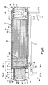
- FIG 2 is a side sectional view of a preferred combustor 56, in accordance with the present invention.
- the combustor 56 comprises a cylindrical metal housing 58 which is lined with two layers of insulating material 60 and 62.
- a preferred insulating material 60 comprises 0.180 inch thick layers of a ceramic material provided by the 3M company under the tradename INTERAM Mat Material.
- the combustor 56 has an input end 64 for receiving the combustor fuels and oxidants and an exhaust end 66 through which hot combustor exhaust gas is discharged from the combustor 56 into the heat exchanger 30 associated with the reformer 2 of Figure 1.
- the exhaust end 66 includes a flange 68 for mounting to the input of the heat exchanger 30 of Figure 1.
- a primary catalyst bed 70 is positioned between the input end 64 and exhaust end 66 for burning the fuel-oxidant reactants and preferably comprises a catalyst-coated extruded ceramic monolith type bed having about 400 cells per inch at the inlet face 72. Such beds are commonly used in automobile catalytic converters. The bed 70 could be broken into two or more sections/stages each separated from the next and each with a different porosity profile if so desired.
- a preferred catalyst comprises platinum, but other precious metals, or combinations thereof, may also be used depending on the performance requirements for the combustor.
- a catalyzed ceramic light-off foam 74 having a porosity profile of about 10 pores per inch and a thickness of about 0.79 inch is provided at the leading face 72 of the monolithic catalyst bed 70.
- the light-off foam 74 may comprise platinum on a silicon carbide foam substrate, and serves to light-off the reactants prior to their entering the catalyst bed 70, and also provides a tortuous path for mixing the reactants and promoting turbulent oxidation reactions.
- a turbulator section T precedes the light-off foam 74 and comprises at least one porous bed of mixing media upstream of the light-off catalyst 74 which provides a tortuous path therethrough to promote turbulent flow, and intimate mixing of the combustor fuel(s) and air before they contact the light-off catalyst 74.
- the turbulator section T will preferably comprise at least two mixing-media beds 76 and 80 with an open chamber 82 between the mixing-media beds to act as a homogenization region for homogenizing the mixture exiting the first mixing-media bed 80 before it enters the second mixing-media bed 76.
- the mixing-media beds 76 and 80 have leading faces 77 and 81 respectively where the reactants enter the beds and trailing faces 79 and 83 respectively where the reactants exit the beds 76 and 80.
- Preferred mixing media comprises ceramic foams having a porosity profile of about 25 pores per lineal inch to about 80 pores per lineal inch, but other materials and porosity profiles may be used.
- a preferred mixing-media for bed 76 comprises silicon carbide foam having a porosity profile of about 25 pores per linear inch and a thickness of about one inch.
- Alternative mixing-media beds include refractory metal foams, ceramic pellets retained in a flow-through container, or a stack of fine (e.g., about 0.001 to about 0.010 openings per inch) metal or ceramic screens, wherein the openings of one screen are offset from the openings in adjacent screens to provide the desired tortuous path.
- the mixing-media bed 76 can also function as a flame suppressor to prevent any flame created at the light-off catalyst 74 from propagating back into the input end 64 of the combustor 56, and as a means to distribute the reaction mixture evenly across the leading face 72 of the catalyst bed 70.
- An electric heating element 78 is provided upstream of the mixing media 76 and serves to vaporize liquid fuel entering the combustor 56, and to heat the gas entering the catalyst bed 70 during initial startup of the combustor 56.
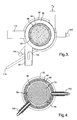
- the heating element 78 may or may not be catalyzed, and is energized by electrical contacts 79 and 79' ( Figure 4) which are provided with electricity via electrical leads 104 and 104'. After startup, the electric heater 78 is no longer required since the fuel will be vaporized by the exhaust gases emanating from the exhaust end 66 of the combustor 56, as will be discussed in more detail hereinafter.
- a preferred electric heater 78 comprises a commercially available, uncatalyzed extruded metal monolith resistance element such as is used to light off the catalyst of a catalytic converter used to treat IC engine exhaust gases.
- Another mixing-media bed 80 of the turbulator section T lies upstream of the electric heater 78.
- the mixing-media 80 provides a tortuous path therethrough and induces turbulent flow for mixing the reactants before they contact the electric heater 78.
- the heater 78 resides in the homogenization space 82 that lies between the mixing-media beds 76 and 80 and further serves to promote mixing of the reactants exiting the first stage mixing media 80 prior to their entering the second stage mixing media 76.
- This first stage mixing media preferably has a smaller pore size than the second stage mixing media 76.
- a suitable turbulator first stage mixing media 80 comprises a ceramic foam comprising ytria-zirconia-alumina having a porosity profile of about 80 pores per linear inch and a thickness of about 0.375 inch.
- the mixing media 80 additionally serves as a flame arrestor to suppress any flame that might result from fuel ignited by the electric heating element 78, or down stream catalyst bed, from propagating back into the mixing chamber 84 where the reactants mix before passing through
- H 2 -containing anode effluent 20 exiting the anode side of the fuel cell 16 enters the input end 64 of the combustor 56 via the annular plenum 86 that surrounds the shell 94 that contains the mixing media 80, and passes through a porous, metal disc 88 into the mixing chamber 92.
- the disc 88 may or may not be cooled (e.g., with water) and serves to diffuse the H 2 therethrough while functioning as a flame arrestor against flame entering into the plenum 86.
- the flame arrestor 88 will preferably comprise a sintered metal disk having a pore size of about 40 microns, and a thickness of about 0.078 inch.
- O 2 -containing cathode effluent 22 exiting the cathode side of the fuel cell 16 enters the input end 64 of the combustor 56, via conduit 90, and swirls in the annular chamber 92 defined centrally by the shell 94.
- the swirling cathode effluent picks up, and to some extent mixes with, the anode effluent passing through the flame arrestor 88.
- a suitable insulating material 96 similar to the insulating material 60 and 62 lines the shell 94 containing the mixing media 80.
- a narrow annular gap 98 (i.e., about 3.0 mm) between the leading edge 95 of the shell 94 and the end wall 100 of the housing 58 insures that some degree of mixing of the cathode and anode effluents occurs in the chamber 92 before they move into the input chamber 97, which is a vestibule to the mixing media 80.
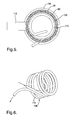
- the exhaust end 66 of the combustor 56 includes a chamber 106 that houses a heat exchanger 108 which, in the embodiment shown, comprises a coil of metal tubing 110. (See Figure 6).
- the heat exchanger 108 is used to vaporize liquid fuel used to fuel the combustor 56. More specifically, under normal post-startup conditions, air or cathode effluent 22 (see Figure 1) may be introduced into the inlet end 114 of the coil 110 and mixed with liquid fuel sprayed into the input end 114 via a conventional automotive type fuel injector 116.
- the airborne atomized fuel passes through the several turns of the heated coil tube 110, and therein vaporizes and exits the heat exchanger 108 at outlet 118 which is located in the cathode effluent supply conduit 90.
- This vaporized fuel supplements the anode effluent 20 (see Figure 1) as fuel for the combustor 56 as may be needed to meet the transient and steady state needs of the fuel cell system.
- the vaporizer coil 110 is sized to vaporize the maximum flow rate of fuel with the minimum combustor exhaust flow rate, and is designed to operate at temperatures exceeding the autoignition temperature of the MeOH-air mixture therein throughout its full operational range.
- the fuel cell system of the present invention operates as follows. At the beginning of operations when the system is cold and starting up: (1) the compressor 24 ( Figure 1) is driven by an electric motor energized from an external source (e.g., a battery) to provide the necessary system air; (2) air is introduced into conduit tube 90 as well as the input end 114 of the tubular heat exchanger 110; (3) liquid fuel (e.g., MeOH) is injected into the inlet end 114 of the tubular heat exchanger 110 via fuel injector 116, and admixed as fine droplets with the air flowing therein; (4) the air-MeOH droplet mix exits the now cold coil 110 at outlet 118 and mixes with compressor air introduced into conduit 90, and is then introduced into the annular chamber 92 in the input end 64 of the combustor 56; (5) the mix passes through the first mixing-media bed 80 of the turbulator section; (6) the mix exiting the mixing-media bed 80 is heated by the heater 78 in the homogenization chamber 82 to vaporize the liquid droplets
- valve 26 is rotated to direct air to the cathode side of the fuel cell 16 ( Figure 1); (2) MeOH and water are fed to the reformer 2 to commence the reformation reaction; (3) reformate exiting the reformer 2 is fed to the anode side of the fuel cell 16; (4) anode effluent 20 from the fuel cell 16 is directed into plenum 86 of the combustor 56; (5) cathode effluent 22 from the fuel cell 16 is directed into annular chamber 92 of the combustor 56; (6) air is introduced into the inlet 114 of the tubular heat exchanger 110; (7) liquid methanol is sprayed into the inlet 114 by the injector 116; (8) the methanol-air mix circulates through the heated tubular heat exchanger coil 110 where the MeOH vaporizes; (9) the Air-MeOH (v) mix exits the heat exchanger at outlet 118 and is fed into the chamber 92 along with
- the heater 78 is not used as the heat exchanger coil 110 alone vaporizes the MeOH and preheats the MeOH-air mix.
- the combustor 56 could operate solely on the anode and cathode effluents alone, without the need for additional MeOH fuel from the heat exchanger 110. Under such conditions, MeOH injection through injector 116 is discontinued. Under other conditions, e.g., increasing power demands, supplemental fuel is provided to the combustor via the injector 116. More such supplemental fuel will be needed in the future as stack fuel efficiencies increase and the H 2 content of the anode effluent 20 and O 2 content of the cathode effluent 22 is reduced.
Landscapes
- Chemical & Material Sciences (AREA)
- Chemical Kinetics & Catalysis (AREA)
- Organic Chemistry (AREA)
- Engineering & Computer Science (AREA)
- General Chemical & Material Sciences (AREA)
- Sustainable Energy (AREA)
- Sustainable Development (AREA)
- Electrochemistry (AREA)
- Life Sciences & Earth Sciences (AREA)
- Manufacturing & Machinery (AREA)
- Combustion & Propulsion (AREA)
- Inorganic Chemistry (AREA)
- General Health & Medical Sciences (AREA)
- Health & Medical Sciences (AREA)
- Physics & Mathematics (AREA)
- Fluid Mechanics (AREA)
- Fuel Cell (AREA)
- Hydrogen, Water And Hydrids (AREA)
Applications Claiming Priority (2)
| Application Number | Priority Date | Filing Date | Title |
|---|---|---|---|
| US08/980,087 US6077620A (en) | 1997-11-26 | 1997-11-26 | Fuel cell system with combustor-heated reformer |
| US980087 | 1997-11-26 |
Publications (1)
| Publication Number | Publication Date |
|---|---|
| EP0920064A1 true EP0920064A1 (de) | 1999-06-02 |
Family
ID=25527356
Family Applications (1)
| Application Number | Title | Priority Date | Filing Date |
|---|---|---|---|
| EP98202192A Withdrawn EP0920064A1 (de) | 1997-11-26 | 1998-06-30 | Brennstoffzellensystem mit einem durch eine Verbrennungseinrichtung geheizten Reformierungsreaktor |
Country Status (4)
| Country | Link |
|---|---|
| US (1) | US6077620A (de) |
| EP (1) | EP0920064A1 (de) |
| JP (1) | JP3349441B2 (de) |
| CA (1) | CA2240298C (de) |
Cited By (31)
| Publication number | Priority date | Publication date | Assignee | Title |
|---|---|---|---|---|
| EP1106569A1 (de) * | 1999-12-02 | 2001-06-13 | XCELLSIS GmbH | Verdampfer für ein Brennstoffzellensystem |
| EP1120845A1 (de) * | 2000-01-25 | 2001-08-01 | Sulzer Hexis AG | Brennstoffzellenbatterie und Reformer für flüssige Brennstoffe |
| WO2001056105A1 (de) * | 2000-01-26 | 2001-08-02 | Ballard Power Systems Ag | System zur vorsorgung von wenigstens zwei komponenten eines gaserzeugungssystems |
| WO2001055026A1 (de) * | 2000-01-26 | 2001-08-02 | Daimlerchrysler Ag | Verfahren zum verdampfen und/oder überhitzen eines brennstoffs |
| EP1129988A1 (de) * | 2000-03-02 | 2001-09-05 | XCELLSIS GmbH | Verfahren zum Betreiben einer Gaserzeugungsvorrichtung bzw. eines Brennstoffzellensystems, Gaserzeugungsvorrichtung und Brennstoffzellensystem |
| WO2001072632A3 (en) * | 2000-03-29 | 2002-03-07 | Uop Llc | Multi-stage combustion for fuel processing for use with fuel cell |
| WO2002085783A3 (en) * | 2001-04-18 | 2002-12-12 | Texaco Development Corp | Integrated fuel processor, fuel cell stack and tail gas oxidizer with carbon dioxide removal |
| WO2001095409A3 (en) * | 2000-05-31 | 2003-03-13 | Nuvera Fuel Cells | Joint-cycle high-efficiency fuel cell system with power generating turbine |
| EP1084991A3 (de) * | 1999-09-17 | 2003-07-09 | DaimlerChrysler AG | Reaktorsystem mit elektrischen Heizmitteln |
| EP1069637A3 (de) * | 1999-07-06 | 2003-08-06 | General Motors Corporation | Luftstromsteurungsverfahren eines Verbrenners für Brennstoffzellenapparat |
| WO2003078046A1 (de) * | 2002-03-19 | 2003-09-25 | Daimlerchrysler Ag | Vorrichtung zur zufuhr von edukten in einen reaktionsraum |
| WO2004035466A1 (en) * | 2002-10-18 | 2004-04-29 | Monsanto Technology Llc | Use of metal supported copper catalysts for reforming alcohols |
| EP1228999A3 (de) * | 2001-02-02 | 2004-06-23 | Ballard Power Systems AG | Gaserzeugungssystem für ein Brennstoffzellensystem und Verfahren zum Betrieb eines Gaserzeugungssystem |
| FR2854501A1 (fr) * | 2002-01-04 | 2004-11-05 | Peugeot Citroen Automobiles Sa | Dispositif de post traitement des gaz effluents d'une pile a combustible, pile a combustible comportant un tel dispositif et vehicule comportant une telle pile |
| US6817182B2 (en) | 2001-12-05 | 2004-11-16 | Lawrence G. Clawson | High-efficiency Otto cycle engine with power generating expander |
| WO2005015674A1 (en) * | 2003-07-26 | 2005-02-17 | Rolls-Royce Fuel Cell Systems Limited | A reformer module |
| US6916564B2 (en) | 2000-05-31 | 2005-07-12 | Nuvera Fuel Cells, Inc. | High-efficiency fuel cell power system with power generating expander |
| WO2004086545A3 (en) * | 2003-03-27 | 2005-12-29 | Nissan Motor | Control device of vehicular fuel cell system and related method |
| EP1439594A3 (de) * | 2002-10-28 | 2006-06-28 | Hewlett-Packard Development Company, L.P. | Brennstoffzelle mit katalytischer Brennkammer zum Austausch von Wärme |
| EP1231184A3 (de) * | 2001-02-13 | 2006-07-19 | Delphi Technologies, Inc. | Methode und Vorrichtung zum Vorwärmen eines Mikroreformers für eine Brennstoffzelle |
| DE19937152B4 (de) * | 1999-08-06 | 2006-09-21 | Nucellsys Gmbh | Kombiniertes Bauteil zur Nachverbrennung von Anodenabgasen eines Brennstoffzellensystems und zum Verdampfen von dem Brennstoffzellensystem zuzuführenden Edukten |
| US7126024B2 (en) | 2001-10-18 | 2006-10-24 | Monsanto Technology Llc | Process and catalyst for dehydrogenating primary alcohols to make carboxylic acid salts |
| EP1411572A4 (de) * | 2001-07-26 | 2007-08-29 | Matsushita Electric Industrial Co Ltd | Brennstoffzellensystem |
| US7329778B2 (en) | 2000-04-11 | 2008-02-12 | Monsanto Technology Llc | Process and catalyst for dehydrogenating primary alcohols to make carboxylic acid salts |
| DE10054139B4 (de) * | 1999-11-08 | 2008-05-08 | General Motors Corp., Detroit | Verfahren und Vorrichtung zur Reformierung eines Kohlenwasserstoffs zur Anwendung in einem Brennstoffzellensystem |
| US7434547B2 (en) | 2004-06-11 | 2008-10-14 | Nuvera Fuel Cells, Inc. | Fuel fired hydrogen generator |
| US7770545B2 (en) | 2006-06-13 | 2010-08-10 | Monsanto Technology Llc | Reformed alcohol power systems |
| US7939051B2 (en) | 2006-05-23 | 2011-05-10 | Idatech, Llc | Hydrogen-producing fuel processing assemblies, heating assemblies, and methods of operating the same |
| EP1611399A4 (de) * | 2003-04-04 | 2015-05-20 | Texaco Development Corp | Anoden-tailgas-oxidierer |
| WO2015120524A1 (pt) * | 2014-02-13 | 2015-08-20 | Universidade De São Paulo - Usp | Processo de produção de hidrogênio, processo de produção de energia em um veículo híbrido, sistema de produção de energia em um veículo híbrido e veículo híbrido |
| EP3121514A4 (de) * | 2014-03-19 | 2017-02-15 | Sumitomo Precision Products Co., Ltd. | Brennkammer und brennstoffzellensystem |
Families Citing this family (133)
| Publication number | Priority date | Publication date | Assignee | Title |
|---|---|---|---|---|
| DE19523109C2 (de) * | 1995-06-26 | 2001-10-11 | Daimler Chrysler Ag | Kraftfahrzeug mit Brennkraftmaschine und einem Stromerzeugungssystem |
| US6783741B2 (en) * | 1996-10-30 | 2004-08-31 | Idatech, Llc | Fuel processing system |
| US7195663B2 (en) | 1996-10-30 | 2007-03-27 | Idatech, Llc | Hydrogen purification membranes, components and fuel processing systems containing the same |
| US6376113B1 (en) * | 1998-11-12 | 2002-04-23 | Idatech, Llc | Integrated fuel cell system |
| US6537352B2 (en) | 1996-10-30 | 2003-03-25 | Idatech, Llc | Hydrogen purification membranes, components and fuel processing systems containing the same |
| US6494937B1 (en) | 2001-09-27 | 2002-12-17 | Idatech, Llc | Hydrogen purification devices, components and fuel processing systems containing the same |
| DE19822691A1 (de) * | 1998-05-20 | 1999-11-25 | Volkswagen Ag | Brennstoffzellensystem und Verfahren zum Erzeugen elektrischer Energie mittels eines Brennstoffzellensystems |
| GR1003235B (el) * | 1998-05-22 | 1999-10-13 | Διεργασια παραγωγης υδρογονου και ηλεκτρικης ενεργειας απο αναμορφωση βιο-αιθανολης, με χρηση κυψελιδων καυσιμου και με μηδενικη εκπομπη ρυπων | |
| US6238815B1 (en) * | 1998-07-29 | 2001-05-29 | General Motors Corporation | Thermally integrated staged methanol reformer and method |
| US6921597B2 (en) * | 1998-09-14 | 2005-07-26 | Questair Technologies Inc. | Electrical current generation system |
| JP3473436B2 (ja) * | 1998-09-16 | 2003-12-02 | 株式会社豊田自動織機 | 燃料電池装置 |
| US6641625B1 (en) * | 1999-05-03 | 2003-11-04 | Nuvera Fuel Cells, Inc. | Integrated hydrocarbon reforming system and controls |
| DE19928102B4 (de) * | 1999-06-19 | 2005-06-02 | Daimlerchrysler Ag | Fahrzeug mit einem Antriebs-Verbrennungsmotor und mit einem Brennstoffzellensystem zur Stromversorgung elektrischer Verbraucher des Fahrzeugs und Verfahren zum Betrieb eines derartigen Fahrzeugs |
| US6375906B1 (en) | 1999-08-12 | 2002-04-23 | Idatech, Llc | Steam reforming method and apparatus incorporating a hydrocarbon feedstock |
| US7135048B1 (en) | 1999-08-12 | 2006-11-14 | Idatech, Llc | Volatile feedstock delivery system and fuel processing system incorporating the same |
| TR200201283T2 (tr) * | 1999-08-19 | 2002-09-23 | Manufacturing And Technology Conversion International, Inc. | Dolaylı olarak ısıtılan buhar yeniden yapılandırıcı sistemli gaz türbini. |
| HK1048647B (en) | 1999-08-19 | 2006-05-04 | Manufacturing And Technology Conversion International, Inc. | System integration of a steam reformer and fuel cell |
| US6653004B1 (en) * | 1999-10-12 | 2003-11-25 | Jeffrey Lewis Barber | Process control for multiple air supplies |
| CA2392115A1 (en) | 1999-11-17 | 2001-05-25 | Neah Power Systems, Inc. | Fuel cells having silicon substrates and/or sol-gel derived support structures |
| US6465118B1 (en) * | 2000-01-03 | 2002-10-15 | Idatech, Llc | System and method for recovering thermal energy from a fuel processing system |
| US6451464B1 (en) * | 2000-01-03 | 2002-09-17 | Idatech, Llc | System and method for early detection of contaminants in a fuel processing system |
| US6376112B1 (en) * | 2000-02-11 | 2002-04-23 | General Motors Corporation | Controlled shutdown of a fuel cell |
| US6394207B1 (en) * | 2000-02-16 | 2002-05-28 | General Motors Corporation | Thermal management of fuel cell powered vehicles |
| US6627339B2 (en) | 2000-04-19 | 2003-09-30 | Delphi Technologies, Inc. | Fuel cell stack integrated with a waste energy recovery system |
| US6562496B2 (en) * | 2000-05-01 | 2003-05-13 | Delphi Technologies, Inc. | Integrated solid oxide fuel cell mechanization and method of using for transportation industry applications |
| US6653005B1 (en) * | 2000-05-10 | 2003-11-25 | University Of Central Florida | Portable hydrogen generator-fuel cell apparatus |
| US7691271B1 (en) | 2007-05-30 | 2010-04-06 | University Of Central Florida Research Foundation, Inc. | Filamentous carbon particles for cleaning oil spills and method of production |
| JP2002080203A (ja) * | 2000-07-07 | 2002-03-19 | Nippon Soken Inc | 改質器 |
| US6749958B2 (en) | 2000-07-10 | 2004-06-15 | Global Thermmelectric Inc. | Integrated module for solid oxide fuel cell systems |
| US6541142B1 (en) * | 2000-10-04 | 2003-04-01 | General Motors Corporation | Fuel cell system having a methanol decomposition reactor |
| ES2640910T3 (es) * | 2000-10-27 | 2017-11-07 | Air Products And Chemicals, Inc. | Sistemas y procesos para proporcionar hidrógeno a células de combustible |
| US7097925B2 (en) * | 2000-10-30 | 2006-08-29 | Questair Technologies Inc. | High temperature fuel cell power plant |
| CA2325072A1 (en) * | 2000-10-30 | 2002-04-30 | Questair Technologies Inc. | Gas separation for molten carbonate fuel cell |
| US6370878B1 (en) | 2000-11-30 | 2002-04-16 | Plug Power Inc. | Recovering heat from fuel cell exhaust |
| KR100929886B1 (ko) * | 2000-12-05 | 2009-12-04 | 텍사코 디벨롭먼트 코포레이션 | 고수소 가스 제조용 콤팩트 연료 처리장치 |
| US6572993B2 (en) * | 2000-12-20 | 2003-06-03 | Visteon Global Technologies, Inc. | Fuel cell systems with controlled anode exhaust |
| WO2002058201A2 (en) * | 2001-01-17 | 2002-07-25 | Engen Group, Inc. | Stationary energy center |
| US6569227B2 (en) * | 2001-09-27 | 2003-05-27 | Idatech, Llc | Hydrogen purification devices, components and fuel processing systems containing the same |
| US20060037476A1 (en) * | 2001-03-08 | 2006-02-23 | Edlund David J | Hydrogen purification devices, components and fuel processing systems containing the same |
| US6716400B2 (en) * | 2001-03-09 | 2004-04-06 | Honda Giken Kogyo Kabushiki Kaisha | Ignition system for a fuel cell hydrogen generator |
| US6703151B2 (en) | 2001-04-18 | 2004-03-09 | Utc Fuel Cells, Llc | Compact precooler |
| AU2002258864A1 (en) * | 2001-04-19 | 2002-11-05 | Delphi Technologies, Inc. | Integrated solid oxide fuel cell system |
| DE10119721A1 (de) * | 2001-04-21 | 2002-10-31 | Bayer Cropscience Gmbh | Herbizide Mittel enthaltend Benzoylcyclohexandione und Safener |
| US6835219B2 (en) * | 2001-05-14 | 2004-12-28 | General Motors Corporation | Rapid startup of fuel processor using water adsorption |
| US6890672B2 (en) | 2001-06-26 | 2005-05-10 | Idatech, Llc | Fuel processor feedstock delivery system |
| US6875246B2 (en) * | 2001-07-20 | 2005-04-05 | General Motors Corporation | Water vapor transfer device for fuel cell reformer |
| US6630260B2 (en) | 2001-07-20 | 2003-10-07 | General Motors Corporation | Water vapor transfer device for a fuel cell power plant |
| DE10136970C2 (de) * | 2001-07-28 | 2003-11-27 | Ballard Power Systems | Vorrichtung zur Erzeugung von wasserstoffhaltigem Gas für eine Brennstoffzellenanlage |
| US6817347B2 (en) | 2001-09-18 | 2004-11-16 | Paul Noble | Fuel converter |
| US6805721B2 (en) | 2002-01-10 | 2004-10-19 | Steven D. Burch | Fuel processor thermal management system |
| US6669463B2 (en) * | 2002-01-11 | 2003-12-30 | General Motors Corporation | Quick start large dynamic range combustor configuration |
| US6838200B2 (en) * | 2002-01-22 | 2005-01-04 | General Motors Corporation | Fuel processing system having gas recirculation for transient operations |
| EP1476524B1 (de) * | 2002-02-19 | 2008-11-19 | International Inc. Honeywell | Wärmeträger mit hohem elektrischem widerstand für brennstoffzellaggregate |
| US20030167690A1 (en) * | 2002-03-05 | 2003-09-11 | Edlund David J. | Feedstock delivery system and fuel processing systems containing the same |
| US6846585B2 (en) * | 2002-03-08 | 2005-01-25 | General Motors Corporation | Method for quick start-up of a fuel processing system using controlled staged oxidation |
| CN100493670C (zh) * | 2002-03-14 | 2009-06-03 | 探索空气技术公司 | 结合压力波动和置换净化进行气体分离的设备和系统 |
| ATE373323T1 (de) * | 2002-03-14 | 2007-09-15 | Questair Technologies Inc | Wasserstoffrückführung für festoxid- brennstoffzellen |
| US7434584B2 (en) * | 2002-03-22 | 2008-10-14 | Vaporgenie, Llc | Vaporization pipe with flame filter |
| US20030223926A1 (en) * | 2002-04-14 | 2003-12-04 | Edlund David J. | Steam reforming fuel processor, burner assembly, and methods of operating the same |
| US6887602B2 (en) * | 2002-04-15 | 2005-05-03 | General Motors Corporation | Rapid response fuel cell system |
| US7172638B2 (en) * | 2002-04-29 | 2007-02-06 | General Motors Corporation | Staged air autothermal reformer for improved startup and operation |
| AU2003248806A1 (en) * | 2002-07-01 | 2004-01-19 | The Regents Of The University Of California | Mems-based fuel cells with integrated catalytic fuel processor and method thereof |
| US7285350B2 (en) * | 2002-09-27 | 2007-10-23 | Questair Technologies Inc. | Enhanced solid oxide fuel cell systems |
| DE10246231A1 (de) * | 2002-10-04 | 2004-04-15 | Robert Bosch Gmbh | Nachbrenneinrichtung |
| US20050053816A1 (en) * | 2002-11-15 | 2005-03-10 | Anuj Bhargava | Burner for combusting the anode exhaust gas stream in a PEM fuel cell power plant |
| CA2415536A1 (en) | 2002-12-31 | 2004-06-30 | Long Manufacturing Ltd. | Reformer for converting fuel to hydrogen |
| US7862631B2 (en) * | 2003-02-07 | 2011-01-04 | Gm Global Technology Operations, Inc. | Fuel processor primary reactor and combustor startup via electrically-heated catalyst |
| EP1652255A2 (de) * | 2003-02-26 | 2006-05-03 | QuestAir Technologies Inc. | Wasserstoffrückführung für hochtemperaturbrennstoffzellen |
| US20040197622A1 (en) * | 2003-04-04 | 2004-10-07 | Texaco Inc. | Method and apparatus for separating liquid from a gas stream |
| US7829227B2 (en) * | 2003-04-04 | 2010-11-09 | Texaco Inc. | Integrated fuel processor apparatus and enclosure and methods of using same |
| US7235217B2 (en) * | 2003-04-04 | 2007-06-26 | Texaco Inc. | Method and apparatus for rapid heating of fuel reforming reactants |
| US7169376B2 (en) * | 2004-06-10 | 2007-01-30 | Chevron U.S.A. Inc. | Method for making hydrogen using a gold containing water-gas shift catalyst |
| US20060127711A1 (en) * | 2004-06-25 | 2006-06-15 | Ultracell Corporation, A California Corporation | Systems and methods for fuel cartridge distribution |
| US8821832B2 (en) | 2003-06-27 | 2014-09-02 | UltraCell, L.L.C. | Fuel processor for use with portable fuel cells |
| US20050008908A1 (en) * | 2003-06-27 | 2005-01-13 | Ultracell Corporation | Portable fuel cartridge for fuel cells |
| US7604673B2 (en) * | 2003-06-27 | 2009-10-20 | Ultracell Corporation | Annular fuel processor and methods |
| EP1639660A4 (de) * | 2003-06-27 | 2009-12-02 | Ultracell Corp | Effiziente mikro-brennstoffzellen-systeme und -verfahren |
| US8318368B2 (en) * | 2003-06-27 | 2012-11-27 | UltraCell, L.L.C. | Portable systems for engine block |
| US7666539B2 (en) * | 2003-06-27 | 2010-02-23 | Ultracell Corporation | Heat efficient portable fuel cell systems |
| US20060156627A1 (en) * | 2003-06-27 | 2006-07-20 | Ultracell Corporation | Fuel processor for use with portable fuel cells |
| EP1644997A4 (de) * | 2003-06-27 | 2011-03-16 | Ultracell Corp | Mikro-brennstoffzellenarchitektur |
| US7150143B2 (en) * | 2003-07-21 | 2006-12-19 | General Electric Company | Hybrid fuel cell-pulse detonation power system |
| US6923642B2 (en) * | 2003-10-08 | 2005-08-02 | General Motors Corporation | Premixed prevaporized combustor |
| US7443803B2 (en) * | 2004-03-23 | 2008-10-28 | Fujitsu Limited | Estimating and managing network traffic |
| US20050255368A1 (en) * | 2004-05-12 | 2005-11-17 | Ultracell Corporation, A California Corporation | High surface area micro fuel cell architecture |
| WO2005113125A2 (en) * | 2004-05-17 | 2005-12-01 | Nuvera Fuel Cells, Inc. | Startup burner |
| WO2006009787A2 (en) * | 2004-06-18 | 2006-01-26 | Nuvera Fuel Cells, Inc. | Device for cooling and humidifying reformate |
| US7968250B2 (en) * | 2004-06-25 | 2011-06-28 | Ultracell Corporation | Fuel cartridge connectivity |
| US7648792B2 (en) * | 2004-06-25 | 2010-01-19 | Ultracell Corporation | Disposable component on a fuel cartridge and for use with a portable fuel cell system |
| US7189280B2 (en) * | 2004-06-29 | 2007-03-13 | Questair Technologies Inc. | Adsorptive separation of gas streams |
| US20060021280A1 (en) * | 2004-07-30 | 2006-02-02 | Hamilton Daniel B | Reformer, and methods of making and using the same |
| WO2006017375A2 (en) | 2004-08-06 | 2006-02-16 | Ultracell Corporation | Method and system for controlling fluid delivery in a fuel cell |
| KR100590038B1 (ko) * | 2004-09-07 | 2006-06-14 | 삼성에스디아이 주식회사 | 연료 전지 시스템 및 연료 공급장치 |
| US7470293B2 (en) * | 2004-10-29 | 2008-12-30 | Idatech, Llc | Feedstock delivery systems, fuel processing systems, and hydrogen generation assemblies including the same |
| WO2006052937A2 (en) * | 2004-11-05 | 2006-05-18 | Questair Technologies, Inc. | Separation of carbon dioxide from other gases |
| US7807313B2 (en) * | 2004-12-21 | 2010-10-05 | Ultracell Corporation | Compact fuel cell package |
| FI119266B (fi) * | 2005-01-03 | 2008-09-15 | Waertsilae Finland Oy | Esilämmitysjärjestely polttokennolaitteistossa |
| US20060194082A1 (en) * | 2005-02-02 | 2006-08-31 | Ultracell Corporation | Systems and methods for protecting a fuel cell |
| US20080112859A1 (en) * | 2005-02-16 | 2008-05-15 | Shigenori Onuma | Fuel Gas Processing Apparatus |
| US20060188763A1 (en) * | 2005-02-22 | 2006-08-24 | Dingrong Bai | Fuel cell system comprising modular design features |
| US7632322B2 (en) * | 2005-06-07 | 2009-12-15 | Idatech, Llc | Hydrogen-producing fuel processing assemblies, heating assemblies, and methods of operating the same |
| JP5373256B2 (ja) * | 2005-08-01 | 2013-12-18 | カシオ計算機株式会社 | 電源システム及び電源システムの制御方法並びに電源システムを備える電子機器 |
| DE102005038733A1 (de) * | 2005-08-16 | 2007-02-22 | Webasto Ag | Brennstoffzellensystem und Verfahren zum Betreiben eines Reformers |
| EP1938415B1 (de) | 2005-09-16 | 2014-05-14 | Dcns Sa | Selbstregelndes eingangsmaterial-abliefersystem und wasserstofferzeugende brennstoffverarbeitungsbaugruppe damit |
| US7601302B2 (en) | 2005-09-16 | 2009-10-13 | Idatech, Llc | Self-regulating feedstock delivery systems and hydrogen-generating fuel processing assemblies and fuel cell systems incorporating the same |
| JP4195055B2 (ja) * | 2006-01-13 | 2008-12-10 | シャープ株式会社 | 燃料電池 |
| EP2008330A4 (de) * | 2006-04-07 | 2009-12-23 | Utc Power Corp | Betrieb einer brennstoffzelle während einer ausfallzeit beim kryogenen wasserstoffabdampfen |
| US20070248860A1 (en) * | 2006-04-21 | 2007-10-25 | Michael Penev | Integrated exhaust combustor and thermal recovery for fuel cells |
| US7972420B2 (en) | 2006-05-22 | 2011-07-05 | Idatech, Llc | Hydrogen-processing assemblies and hydrogen-producing systems and fuel cell systems including the same |
| US7629067B2 (en) * | 2006-05-22 | 2009-12-08 | Idatech, Llc | Hydrogen-producing fuel processing systems and fuel cell systems with a liquid leak detection system |
| FI119490B (fi) * | 2006-06-22 | 2008-11-28 | Waertsilae Finland Oy | Esilämmitysjärjestely polttokennolaitteistossa |
| KR100805582B1 (ko) * | 2006-08-16 | 2008-02-20 | 삼성에스디아이 주식회사 | 연료전지 시스템용 가열기 |
| US8026020B2 (en) | 2007-05-08 | 2011-09-27 | Relion, Inc. | Proton exchange membrane fuel cell stack and fuel cell stack module |
| US9293778B2 (en) | 2007-06-11 | 2016-03-22 | Emergent Power Inc. | Proton exchange membrane fuel cell |
| US8003274B2 (en) | 2007-10-25 | 2011-08-23 | Relion, Inc. | Direct liquid fuel cell |
| US8262752B2 (en) | 2007-12-17 | 2012-09-11 | Idatech, Llc | Systems and methods for reliable feedstock delivery at variable delivery rates |
| US20090253092A1 (en) * | 2008-04-07 | 2009-10-08 | Hunter Manufacturing Co. | Fuel cell heater |
| JP5408420B2 (ja) * | 2009-07-30 | 2014-02-05 | 日産自動車株式会社 | 燃料電池システムとこの燃料電池システムに用いる燃料電池の昇温方法 |
| JP5769695B2 (ja) * | 2012-12-25 | 2015-08-26 | 三菱日立パワーシステムズ株式会社 | 発電システム及び発電システムの停止方法 |
| JP6053560B2 (ja) * | 2013-02-20 | 2016-12-27 | 三菱日立パワーシステムズ株式会社 | 発電システム及び発電システムの運転方法 |
| EP2772976B1 (de) * | 2013-02-27 | 2017-11-15 | Airbus Defence and Space GmbH | Regeneratives Brennstoffzellensystem mit Gasreinigung |
| JP6283269B2 (ja) * | 2014-06-11 | 2018-02-21 | 本田技研工業株式会社 | 燃料電池モジュール |
| JP6406704B2 (ja) * | 2015-01-26 | 2018-10-17 | 本田技研工業株式会社 | 燃料電池モジュール |
| US10476093B2 (en) | 2016-04-15 | 2019-11-12 | Chung-Hsin Electric & Machinery Mfg. Corp. | Membrane modules for hydrogen separation and fuel processors and fuel cell systems including the same |
| CN110268567B (zh) * | 2017-02-09 | 2022-10-18 | Avl李斯特有限公司 | 用于燃料电池系统的启动燃烧器 |
| JP6777238B2 (ja) * | 2017-07-31 | 2020-10-28 | 日産自動車株式会社 | 燃料電池システムおよび燃料電池システムの制御方法 |
| US10991963B2 (en) * | 2018-07-10 | 2021-04-27 | Cummins Enterprise Llc | Fuel cell system and control method thereof |
| WO2020105190A1 (ja) * | 2018-11-22 | 2020-05-28 | 日産自動車株式会社 | 燃焼システムおよび燃焼システムの制御方法 |
| US10787363B2 (en) * | 2018-12-27 | 2020-09-29 | Automotive Research & Testing Center | Hydrogen producing apparatus with emulsifier |
| CN114342132B (zh) | 2019-09-04 | 2024-06-25 | 日产自动车株式会社 | 燃烧器和具备该燃烧器的燃料电池系统 |
| EP4057399A4 (de) | 2019-11-07 | 2024-08-21 | NISSAN MOTOR Co., Ltd. | Brennstoffzellensystem |
| US11712655B2 (en) | 2020-11-30 | 2023-08-01 | H2 Powertech, Llc | Membrane-based hydrogen purifiers |
| EP4261959A4 (de) * | 2020-12-10 | 2025-01-08 | Nissan Motor Co., Ltd. | Brennstoffzellensystem |
Citations (12)
| Publication number | Priority date | Publication date | Assignee | Title |
|---|---|---|---|---|
| JPS61197402A (ja) * | 1985-02-27 | 1986-09-01 | Hitachi Ltd | 燃料電池用燃料改質装置 |
| JPS6217002A (ja) * | 1985-07-15 | 1987-01-26 | Babcock Hitachi Kk | 燃料電池用メタノ−ル改質装置 |
| US4650727A (en) * | 1986-01-28 | 1987-03-17 | The United States Of America As Represented By The United States Department Of Energy | Fuel processor for fuel cell power system |
| JPS63144101A (ja) * | 1986-12-03 | 1988-06-16 | Hitachi Ltd | 燃料改質システム |
| JPS63230501A (ja) * | 1987-03-19 | 1988-09-27 | Mitsubishi Heavy Ind Ltd | 燃料電池用メタノ−ル改質装置 |
| JPS63248075A (ja) * | 1987-04-01 | 1988-10-14 | Mitsubishi Heavy Ind Ltd | 燃料改質装置 |
| JPS6459778A (en) * | 1987-08-29 | 1989-03-07 | Fuji Electric Res | Fuel cell facility |
| JPH02119061A (ja) * | 1988-10-27 | 1990-05-07 | Sanyo Electric Co Ltd | 燃料電池のメタノール改質装置 |
| JPH03129674A (ja) * | 1989-10-13 | 1991-06-03 | Fuji Electric Co Ltd | 燃料電池用改質装置の起動方法 |
| JPH03218902A (ja) * | 1990-01-23 | 1991-09-26 | Mitsubishi Heavy Ind Ltd | 水素原料改質装置の始動方法 |
| EP0729196A1 (de) * | 1995-02-27 | 1996-08-28 | FINMECCANICA S.p.A. AZIENDA ANSALDO | Brennstoffzelle mit integriertem katalytischem Reaktor zur Verfertigung von Wasserstoff |
| EP0924786A2 (de) * | 1997-11-20 | 1999-06-23 | General Motors Corporation | Brennervorrichtung für Brennstoffzellensystem |
Family Cites Families (14)
| Publication number | Priority date | Publication date | Assignee | Title |
|---|---|---|---|---|
| US4659634A (en) * | 1984-12-18 | 1987-04-21 | Struthers Ralph C | Methanol hydrogen fuel cell system |
| US4670359A (en) * | 1985-06-10 | 1987-06-02 | Engelhard Corporation | Fuel cell integrated with steam reformer |
| JPS6344931A (ja) * | 1986-08-13 | 1988-02-25 | Fuji Electric Co Ltd | 燃料改質装置 |
| US4678723A (en) * | 1986-11-03 | 1987-07-07 | International Fuel Cells Corporation | High pressure low heat rate phosphoric acid fuel cell stack |
| JPH02168569A (ja) * | 1988-08-22 | 1990-06-28 | Fuji Electric Co Ltd | 燃料電池発電システム |
| US4994331A (en) * | 1989-08-28 | 1991-02-19 | International Fuel Cells Corporation | Fuel cell evaporative cooling using fuel as a carrier gas |
| JP3062219B2 (ja) * | 1990-06-26 | 2000-07-10 | 富士電機株式会社 | 燃料電池用燃料改質器の熱媒体加熱装置 |
| US5372617A (en) * | 1993-05-28 | 1994-12-13 | The Charles Stark Draper Laboratory, Inc. | Hydrogen generation by hydrolysis of hydrides for undersea vehicle fuel cell energy systems |
| US5429886A (en) * | 1993-08-30 | 1995-07-04 | Struthers; Ralph C. | Hydrocarbon (hydrogen)/air aerogel catalyzed carbon electrode fuel cell system |
| US5484577A (en) * | 1994-05-27 | 1996-01-16 | Ballard Power System Inc. | Catalytic hydrocarbon reformer with enhanced internal heat transfer mechanism |
| US5518828A (en) * | 1994-07-21 | 1996-05-21 | Bechtel Group, Inc. | Thermal integration of an air-cooled fuel cell stack |
| JP3509948B2 (ja) * | 1994-09-19 | 2004-03-22 | 石川島播磨重工業株式会社 | 燃料電池発電装置 |
| US5554453A (en) * | 1995-01-04 | 1996-09-10 | Energy Research Corporation | Carbonate fuel cell system with thermally integrated gasification |
| EP0741428A1 (de) * | 1995-05-04 | 1996-11-06 | FINMECCANICA S.p.A. AZIENDA ANSALDO | Zuführungssystem für Brennstoffzellen der Art SPE (Festpolymerelektrolyt) für Hybridfahrzeugen |
-
1997
- 1997-11-26 US US08/980,087 patent/US6077620A/en not_active Expired - Fee Related
-
1998
- 1998-06-11 CA CA002240298A patent/CA2240298C/en not_active Expired - Fee Related
- 1998-06-30 EP EP98202192A patent/EP0920064A1/de not_active Withdrawn
- 1998-07-23 JP JP20814398A patent/JP3349441B2/ja not_active Expired - Fee Related
Patent Citations (12)
| Publication number | Priority date | Publication date | Assignee | Title |
|---|---|---|---|---|
| JPS61197402A (ja) * | 1985-02-27 | 1986-09-01 | Hitachi Ltd | 燃料電池用燃料改質装置 |
| JPS6217002A (ja) * | 1985-07-15 | 1987-01-26 | Babcock Hitachi Kk | 燃料電池用メタノ−ル改質装置 |
| US4650727A (en) * | 1986-01-28 | 1987-03-17 | The United States Of America As Represented By The United States Department Of Energy | Fuel processor for fuel cell power system |
| JPS63144101A (ja) * | 1986-12-03 | 1988-06-16 | Hitachi Ltd | 燃料改質システム |
| JPS63230501A (ja) * | 1987-03-19 | 1988-09-27 | Mitsubishi Heavy Ind Ltd | 燃料電池用メタノ−ル改質装置 |
| JPS63248075A (ja) * | 1987-04-01 | 1988-10-14 | Mitsubishi Heavy Ind Ltd | 燃料改質装置 |
| JPS6459778A (en) * | 1987-08-29 | 1989-03-07 | Fuji Electric Res | Fuel cell facility |
| JPH02119061A (ja) * | 1988-10-27 | 1990-05-07 | Sanyo Electric Co Ltd | 燃料電池のメタノール改質装置 |
| JPH03129674A (ja) * | 1989-10-13 | 1991-06-03 | Fuji Electric Co Ltd | 燃料電池用改質装置の起動方法 |
| JPH03218902A (ja) * | 1990-01-23 | 1991-09-26 | Mitsubishi Heavy Ind Ltd | 水素原料改質装置の始動方法 |
| EP0729196A1 (de) * | 1995-02-27 | 1996-08-28 | FINMECCANICA S.p.A. AZIENDA ANSALDO | Brennstoffzelle mit integriertem katalytischem Reaktor zur Verfertigung von Wasserstoff |
| EP0924786A2 (de) * | 1997-11-20 | 1999-06-23 | General Motors Corporation | Brennervorrichtung für Brennstoffzellensystem |
Non-Patent Citations (11)
| Title |
|---|
| DATABASE WPI Derwent World Patents Index; AN 88-312105, XP002098510 * |
| DATABASE WPI Derwent World Patents Index; AN 91-328577, XP002098509 * |
| PATENT ABSTRACTS OF JAPAN vol. 011, no. 024 (C - 399) 23 January 1987 (1987-01-23) * |
| PATENT ABSTRACTS OF JAPAN vol. 011, no. 193 (C - 430) 20 June 1987 (1987-06-20) * |
| PATENT ABSTRACTS OF JAPAN vol. 012, no. 405 (C - 539) 26 October 1988 (1988-10-26) * |
| PATENT ABSTRACTS OF JAPAN vol. 013, no. 024 (C - 561) 19 January 1989 (1989-01-19) * |
| PATENT ABSTRACTS OF JAPAN vol. 013, no. 058 (E - 714) 9 February 1989 (1989-02-09) * |
| PATENT ABSTRACTS OF JAPAN vol. 013, no. 268 (E - 775) 20 June 1989 (1989-06-20) * |
| PATENT ABSTRACTS OF JAPAN vol. 014, no. 344 (E - 0955) 25 July 1990 (1990-07-25) * |
| PATENT ABSTRACTS OF JAPAN vol. 015, no. 340 (E - 1105) 28 August 1991 (1991-08-28) * |
| PATENT ABSTRACTS OF JAPAN vol. 015, no. 500 (C - 0895) 18 December 1991 (1991-12-18) * |
Cited By (48)
| Publication number | Priority date | Publication date | Assignee | Title |
|---|---|---|---|---|
| EP1069637A3 (de) * | 1999-07-06 | 2003-08-06 | General Motors Corporation | Luftstromsteurungsverfahren eines Verbrenners für Brennstoffzellenapparat |
| DE19937152B4 (de) * | 1999-08-06 | 2006-09-21 | Nucellsys Gmbh | Kombiniertes Bauteil zur Nachverbrennung von Anodenabgasen eines Brennstoffzellensystems und zum Verdampfen von dem Brennstoffzellensystem zuzuführenden Edukten |
| US7025941B1 (en) | 1999-09-17 | 2006-04-11 | Daimlerchrysler Ag | Reactor system with electric heating means |
| EP1084991A3 (de) * | 1999-09-17 | 2003-07-09 | DaimlerChrysler AG | Reaktorsystem mit elektrischen Heizmitteln |
| DE10054139B4 (de) * | 1999-11-08 | 2008-05-08 | General Motors Corp., Detroit | Verfahren und Vorrichtung zur Reformierung eines Kohlenwasserstoffs zur Anwendung in einem Brennstoffzellensystem |
| EP1106569A1 (de) * | 1999-12-02 | 2001-06-13 | XCELLSIS GmbH | Verdampfer für ein Brennstoffzellensystem |
| US6682840B2 (en) | 1999-12-02 | 2004-01-27 | Ballard Power Systems Ag | Fuel cell system having an evaporator |
| EP1120845A1 (de) * | 2000-01-25 | 2001-08-01 | Sulzer Hexis AG | Brennstoffzellenbatterie und Reformer für flüssige Brennstoffe |
| WO2001055026A1 (de) * | 2000-01-26 | 2001-08-02 | Daimlerchrysler Ag | Verfahren zum verdampfen und/oder überhitzen eines brennstoffs |
| DE10003275B4 (de) * | 2000-01-26 | 2007-05-03 | Daimlerchrysler Ag | Vorrichtung zum Verdampfen und/oder Überhitzen eines Brennstoffs |
| WO2001056105A1 (de) * | 2000-01-26 | 2001-08-02 | Ballard Power Systems Ag | System zur vorsorgung von wenigstens zwei komponenten eines gaserzeugungssystems |
| US6866091B2 (en) | 2000-01-26 | 2005-03-15 | Daimlerchrysler Ag | Device for vaporizing and/or superheating a combustible |
| US7135244B2 (en) | 2000-01-26 | 2006-11-14 | Nucellsys Gmbh | System to supply at least two components of a gas generation system |
| EP1129988A1 (de) * | 2000-03-02 | 2001-09-05 | XCELLSIS GmbH | Verfahren zum Betreiben einer Gaserzeugungsvorrichtung bzw. eines Brennstoffzellensystems, Gaserzeugungsvorrichtung und Brennstoffzellensystem |
| WO2001072632A3 (en) * | 2000-03-29 | 2002-03-07 | Uop Llc | Multi-stage combustion for fuel processing for use with fuel cell |
| US8298985B2 (en) | 2000-04-11 | 2012-10-30 | Monsanto Technology Llc | Catalyst for dehydrogenating primary alcohols |
| US7329778B2 (en) | 2000-04-11 | 2008-02-12 | Monsanto Technology Llc | Process and catalyst for dehydrogenating primary alcohols to make carboxylic acid salts |
| US8450523B2 (en) | 2000-04-11 | 2013-05-28 | Monsanto Technology Llc | Process for preparation of a carboxylic acid salt by dehydrogenation of a primary alcohol |
| US6916564B2 (en) | 2000-05-31 | 2005-07-12 | Nuvera Fuel Cells, Inc. | High-efficiency fuel cell power system with power generating expander |
| US6921595B2 (en) | 2000-05-31 | 2005-07-26 | Nuvera Fuel Cells, Inc. | Joint-cycle high-efficiency fuel cell system with power generating turbine |
| WO2001095409A3 (en) * | 2000-05-31 | 2003-03-13 | Nuvera Fuel Cells | Joint-cycle high-efficiency fuel cell system with power generating turbine |
| EP1228999A3 (de) * | 2001-02-02 | 2004-06-23 | Ballard Power Systems AG | Gaserzeugungssystem für ein Brennstoffzellensystem und Verfahren zum Betrieb eines Gaserzeugungssystem |
| EP1231184A3 (de) * | 2001-02-13 | 2006-07-19 | Delphi Technologies, Inc. | Methode und Vorrichtung zum Vorwärmen eines Mikroreformers für eine Brennstoffzelle |
| KR100952343B1 (ko) * | 2001-04-18 | 2010-04-13 | 텍사코 디벨롭먼트 코포레이션 | 탄화수소 연료 처리 방법 및 장치, 연료 전지 조작 방법 |
| US6682838B2 (en) | 2001-04-18 | 2004-01-27 | Texaco Inc. | Integrated fuel processor, fuel cell stack, and tail gas oxidizer with carbon dioxide removal |
| WO2002085783A3 (en) * | 2001-04-18 | 2002-12-12 | Texaco Development Corp | Integrated fuel processor, fuel cell stack and tail gas oxidizer with carbon dioxide removal |
| EP1411572A4 (de) * | 2001-07-26 | 2007-08-29 | Matsushita Electric Industrial Co Ltd | Brennstoffzellensystem |
| US7126024B2 (en) | 2001-10-18 | 2006-10-24 | Monsanto Technology Llc | Process and catalyst for dehydrogenating primary alcohols to make carboxylic acid salts |
| US6817182B2 (en) | 2001-12-05 | 2004-11-16 | Lawrence G. Clawson | High-efficiency Otto cycle engine with power generating expander |
| US7062915B2 (en) | 2001-12-05 | 2006-06-20 | Clawson Lawrence G | High-efficiency otto cycle engine with power generating expander |
| FR2854501A1 (fr) * | 2002-01-04 | 2004-11-05 | Peugeot Citroen Automobiles Sa | Dispositif de post traitement des gaz effluents d'une pile a combustible, pile a combustible comportant un tel dispositif et vehicule comportant une telle pile |
| WO2003078046A1 (de) * | 2002-03-19 | 2003-09-25 | Daimlerchrysler Ag | Vorrichtung zur zufuhr von edukten in einen reaktionsraum |
| US7682724B2 (en) | 2002-10-18 | 2010-03-23 | Monsanto Technology Llc | Use of metal supported copper catalysts for reforming alcohols |
| WO2004035466A1 (en) * | 2002-10-18 | 2004-04-29 | Monsanto Technology Llc | Use of metal supported copper catalysts for reforming alcohols |
| EP1439594A3 (de) * | 2002-10-28 | 2006-06-28 | Hewlett-Packard Development Company, L.P. | Brennstoffzelle mit katalytischer Brennkammer zum Austausch von Wärme |
| US8034497B2 (en) | 2003-03-27 | 2011-10-11 | Nissan Motor Co., Ltd. | Control device of vehicular fuel cell system and related method |
| WO2004086545A3 (en) * | 2003-03-27 | 2005-12-29 | Nissan Motor | Control device of vehicular fuel cell system and related method |
| EP1611399A4 (de) * | 2003-04-04 | 2015-05-20 | Texaco Development Corp | Anoden-tailgas-oxidierer |
| US7749465B2 (en) | 2003-07-26 | 2010-07-06 | Rolls-Royce Plc | Reformer module |
| US8043576B2 (en) | 2003-07-26 | 2011-10-25 | Rolls-Royce Plc | Reformer module |
| AU2004302054B2 (en) * | 2003-07-26 | 2009-12-17 | Lg Fuel Cell Systems Inc. | A reformer module |
| WO2005015674A1 (en) * | 2003-07-26 | 2005-02-17 | Rolls-Royce Fuel Cell Systems Limited | A reformer module |
| US7434547B2 (en) | 2004-06-11 | 2008-10-14 | Nuvera Fuel Cells, Inc. | Fuel fired hydrogen generator |
| US7939051B2 (en) | 2006-05-23 | 2011-05-10 | Idatech, Llc | Hydrogen-producing fuel processing assemblies, heating assemblies, and methods of operating the same |
| US7770545B2 (en) | 2006-06-13 | 2010-08-10 | Monsanto Technology Llc | Reformed alcohol power systems |
| US8100093B2 (en) | 2006-06-13 | 2012-01-24 | Monsanto Technology Llc | Reformed alcohol power systems |
| WO2015120524A1 (pt) * | 2014-02-13 | 2015-08-20 | Universidade De São Paulo - Usp | Processo de produção de hidrogênio, processo de produção de energia em um veículo híbrido, sistema de produção de energia em um veículo híbrido e veículo híbrido |
| EP3121514A4 (de) * | 2014-03-19 | 2017-02-15 | Sumitomo Precision Products Co., Ltd. | Brennkammer und brennstoffzellensystem |
Also Published As
| Publication number | Publication date |
|---|---|
| JP3349441B2 (ja) | 2002-11-25 |
| CA2240298A1 (en) | 1999-05-26 |
| CA2240298C (en) | 2003-03-18 |
| JPH11176461A (ja) | 1999-07-02 |
| US6077620A (en) | 2000-06-20 |
Similar Documents
| Publication | Publication Date | Title |
|---|---|---|
| US6077620A (en) | Fuel cell system with combustor-heated reformer | |
| EP0924786B1 (de) | Brennervorrichtung für Brennstoffzellensystem | |
| US6528191B1 (en) | Apparatus for monitoring a hydrogen containing gas stream | |
| US6921516B2 (en) | Reactor system including auto ignition and carbon suppression foam | |
| US6521204B1 (en) | Method for operating a combination partial oxidation and steam reforming fuel processor | |
| US6406806B1 (en) | Fuel cell voltage monitoring and system control | |
| JP4340315B2 (ja) | 燃料電池パワープラント及び燃料電池パワープラントを作動させる方法 | |
| US6936238B2 (en) | Compact partial oxidation/steam reactor with integrated air preheater, fuel and water vaporizer | |
| EP1231183B1 (de) | Brennstoffreformersystem | |
| US6669463B2 (en) | Quick start large dynamic range combustor configuration | |
| US6596424B2 (en) | Apparatus for mixing fuel and an oxidant | |
| WO2002069430A2 (en) | Internal reforming improvements for fuel cells | |
| EP1231184A2 (de) | Methode und Vorrichtung zum Vorwärmen eines Mikroreformers für eine Brennstoffzelle | |
| US6805721B2 (en) | Fuel processor thermal management system | |
| US6455180B1 (en) | Flexible method for monitoring fuel cell voltage | |
| US7261749B2 (en) | Multi-port autothermal reformer | |
| KR100774574B1 (ko) | 보조전원 유닛용 고체산화물 연료전지 발전시스템과 그기동방법 | |
| US20040148862A1 (en) | WGS reactor incorporated with catalyzed heat exchanger for WGS reactor volume reduction |
Legal Events
| Date | Code | Title | Description |
|---|---|---|---|
| PUAI | Public reference made under article 153(3) epc to a published international application that has entered the european phase |
Free format text: ORIGINAL CODE: 0009012 |
|
| AK | Designated contracting states |
Kind code of ref document: A1 Designated state(s): DE FR GB IT |
|
| AX | Request for extension of the european patent |
Free format text: AL;LT;LV;MK;RO;SI |
|
| AKX | Designation fees paid | ||
| REG | Reference to a national code |
Ref country code: DE Ref legal event code: 8566 |
|
| RBV | Designated contracting states (corrected) |
Designated state(s): DE FR GB IT |
|
| 17P | Request for examination filed |
Effective date: 20000221 |
|
| 17Q | First examination report despatched |
Effective date: 20011109 |
|
| STAA | Information on the status of an ep patent application or granted ep patent |
Free format text: STATUS: THE APPLICATION HAS BEEN WITHDRAWN |
|
| 18W | Application withdrawn |
Effective date: 20041123 |