EP0920183A1 - Vorlageleser - Google Patents
Vorlageleser Download PDFInfo
- Publication number
- EP0920183A1 EP0920183A1 EP98928531A EP98928531A EP0920183A1 EP 0920183 A1 EP0920183 A1 EP 0920183A1 EP 98928531 A EP98928531 A EP 98928531A EP 98928531 A EP98928531 A EP 98928531A EP 0920183 A1 EP0920183 A1 EP 0920183A1
- Authority
- EP
- European Patent Office
- Prior art keywords
- lens
- optical axis
- resolution
- original reader
- unit
- Prior art date
- Legal status (The legal status is an assumption and is not a legal conclusion. Google has not performed a legal analysis and makes no representation as to the accuracy of the status listed.)
- Ceased
Links
Images






Classifications
-
- H—ELECTRICITY
- H04—ELECTRIC COMMUNICATION TECHNIQUE
- H04N—PICTORIAL COMMUNICATION, e.g. TELEVISION
- H04N1/00—Scanning, transmission or reproduction of documents or the like, e.g. facsimile transmission; Details thereof
- H04N1/04—Scanning arrangements, i.e. arrangements for the displacement of active reading or reproducing elements relative to the original or reproducing medium, or vice versa
- H04N1/0402—Scanning different formats; Scanning with different densities of dots per unit length, e.g. different numbers of dots per inch (dpi); Conversion of scanning standards
- H04N1/0408—Different densities of dots per unit length
-
- H—ELECTRICITY
- H04—ELECTRIC COMMUNICATION TECHNIQUE
- H04N—PICTORIAL COMMUNICATION, e.g. TELEVISION
- H04N1/00—Scanning, transmission or reproduction of documents or the like, e.g. facsimile transmission; Details thereof
- H04N1/04—Scanning arrangements, i.e. arrangements for the displacement of active reading or reproducing elements relative to the original or reproducing medium, or vice versa
- H04N1/0402—Scanning different formats; Scanning with different densities of dots per unit length, e.g. different numbers of dots per inch (dpi); Conversion of scanning standards
-
- H—ELECTRICITY
- H04—ELECTRIC COMMUNICATION TECHNIQUE
- H04N—PICTORIAL COMMUNICATION, e.g. TELEVISION
- H04N1/00—Scanning, transmission or reproduction of documents or the like, e.g. facsimile transmission; Details thereof
- H04N1/04—Scanning arrangements, i.e. arrangements for the displacement of active reading or reproducing elements relative to the original or reproducing medium, or vice versa
- H04N1/0402—Scanning different formats; Scanning with different densities of dots per unit length, e.g. different numbers of dots per inch (dpi); Conversion of scanning standards
- H04N1/0408—Different densities of dots per unit length
- H04N1/0411—Different densities of dots per unit length in the main scanning direction
-
- H—ELECTRICITY
- H04—ELECTRIC COMMUNICATION TECHNIQUE
- H04N—PICTORIAL COMMUNICATION, e.g. TELEVISION
- H04N1/00—Scanning, transmission or reproduction of documents or the like, e.g. facsimile transmission; Details thereof
- H04N1/04—Scanning arrangements, i.e. arrangements for the displacement of active reading or reproducing elements relative to the original or reproducing medium, or vice versa
- H04N1/0402—Scanning different formats; Scanning with different densities of dots per unit length, e.g. different numbers of dots per inch (dpi); Conversion of scanning standards
- H04N1/042—Details of the method used
- H04N1/0435—Optical element switching, e.g. switching lenses into a single optical path
-
- H—ELECTRICITY
- H04—ELECTRIC COMMUNICATION TECHNIQUE
- H04N—PICTORIAL COMMUNICATION, e.g. TELEVISION
- H04N1/00—Scanning, transmission or reproduction of documents or the like, e.g. facsimile transmission; Details thereof
- H04N1/04—Scanning arrangements, i.e. arrangements for the displacement of active reading or reproducing elements relative to the original or reproducing medium, or vice versa
- H04N1/0402—Scanning different formats; Scanning with different densities of dots per unit length, e.g. different numbers of dots per inch (dpi); Conversion of scanning standards
- H04N1/042—Details of the method used
- H04N1/0455—Details of the method used using a single set of scanning elements, e.g. the whole of and a part of an array respectively for different formats
-
- H—ELECTRICITY
- H04—ELECTRIC COMMUNICATION TECHNIQUE
- H04N—PICTORIAL COMMUNICATION, e.g. TELEVISION
- H04N1/00—Scanning, transmission or reproduction of documents or the like, e.g. facsimile transmission; Details thereof
- H04N1/387—Composing, repositioning or otherwise geometrically modifying originals
- H04N1/393—Enlarging or reducing
-
- H—ELECTRICITY
- H04—ELECTRIC COMMUNICATION TECHNIQUE
- H04N—PICTORIAL COMMUNICATION, e.g. TELEVISION
- H04N1/00—Scanning, transmission or reproduction of documents or the like, e.g. facsimile transmission; Details thereof
- H04N1/04—Scanning arrangements, i.e. arrangements for the displacement of active reading or reproducing elements relative to the original or reproducing medium, or vice versa
- H04N1/19—Scanning arrangements, i.e. arrangements for the displacement of active reading or reproducing elements relative to the original or reproducing medium, or vice versa using multi-element arrays
- H04N1/191—Scanning arrangements, i.e. arrangements for the displacement of active reading or reproducing elements relative to the original or reproducing medium, or vice versa using multi-element arrays the array comprising a one-dimensional [1D] array
- H04N1/192—Simultaneously or substantially simultaneously scanning picture elements on one main scanning line
- H04N1/193—Simultaneously or substantially simultaneously scanning picture elements on one main scanning line using electrically scanned linear arrays, e.g. linear CCD arrays
Definitions
- This invention relates to an original reader such us an image scanner that reads image information on a manuscript, and especially relates to an original reader that provides a system for changing the optical resolution thereof.
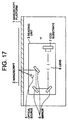
- FIG 17 A prior art flatbed type of original reader is shown in figure 17.
- a transparent manuscript platform 1 a manuscript 2, a reading unit 3 movable in the direction shown by the arrow (sub-scan direction), an optical source 4, lenses 6, and CCD (solid-state image sensor) substrate 7 are shown.
- an optical source 4 lenses 6, and CCD (solid-state image sensor) substrate 7 are shown.
- a surface of the manuscript 2 placed on the manuscript platform 1 is lighted by the optical source 4 of the reading unit 3.
- the reflected light from the manuscript surface 2 follows a rectangular path through the mirror 5, passes through the lens 6, and reaches CCD substrate 7 to be transformed into an electrical signal.
- the reading resolution of the manuscript 2 depends on the focal length of lens 6. The longer the focus is, the greater the magnification and the higher the resolution, but by these technique, the image angle becomes smaller, so the main scan size becomes also smaller.
- zoom lens system may change magnification or resolution continuously by using a zoom lens.
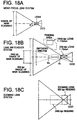
- Figures 18 (a),(b),and (c) show diagrams of original reader of the prior art.
- Figure 18 (a) shows a mono focus lens system in which an image angle is fixed by ⁇ and a main scanning range of the original reader is fixed.
- Figure 18 (b) shows an example of a lens switchover system in which either a field angle of ⁇ 1 of which a lens of focus length is 75 mm, or field angle of ⁇ 2 of which a lens focus length is 115 mm, is able to be chosen.
- the resolution of 800 dpi is obtained by an angle of view of ⁇ 1
- the resolution of 2400 dpi is obtained by an angle of view of ⁇ 2.
- Figure 18 (c) shows a zoom lens system, and that resolution is changeable continuously from 800 dpi to 2400 dpi by changing zoom ratio.
- the prior original reader having a lens switchover system provides lenses grouped in one unit, but the lens unit is movable in only one direction, such as a rectangular direction, of the optical axis for changing the lenses.
- the lens unit is movable in only one direction, such as a rectangular direction, of the optical axis for changing the lenses.
- lenses of which the focus length are different are inserted at different positions on optical axis.
- lenses which are not used are evacuated so as not to obstruct the optical angle of the lens being used. Therefore, there is a problem in that the lens unit needs a large amount of space, results in a greater device size.
- the lens unit provides only a moving means for changing the lens, a high resolution lens of depth of field and depth of focus are sensible to environmental conditions like floating of the manuscript and temperature.
- An object of the present invention is to realize original reader including a wide range of resolution, low cost, high accuracy, and compact size.
- the present invention comprises the following items as components thereof.
- Figure 1 shows a principle of the present invention.
- 8 is a lens unit
- 9 is an image plane
- 10 is an image forming plane.
- the lens unit 8 shown in figure 1 includes three kinds of lenses corresponding to resolution level 1, resolution level 2 and resolution level 3, and they are housed upper and below in direction relative to the drawing.
- the level order of resolution of the lenses is resolution 3 ⁇ resolution 1 ⁇ resolution 2.
- the lens unit 8 moves up or down to be inserted into the path of the optical axis, and moves right and left in the optical direction so that an image of the image plane is formed exactly on the image forming plane.
- lens unit 8 when reading by resolution 2, lens unit 8 is placed at the most right side so that lens of center position is inserted into the path of the optical axes.
- the lens unit 8 when reading by resolution 3, the lens unit 8 is positioned to the most left side so that the lower position lens is inserted into the axis of the optical axis.
- the lens unit 8 is positioned at middle position so that the most upper positioned lens is inserted into the path of the optical axis.
- the lenses are changed corresponding to each resolution and the optimized position for focusing at the optical axis is set and the optical angle corresponding to the resolution is obtained.
- a CCD substrate placed on the image forming plane 10 is movable in a direction of the axis, and magnifying and focusing are controlled exactly by changing the optical length from the manuscript plane or lens to the CCD substrate.
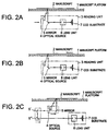
- FIGS 2 (a), (b) and (c) show typical embodiments of an original reader of the present invention.
- Figure 2 (a) shows a case of flat type original reader for reading manuscript .
- 1 reference number 1
- 2 manuscript set on the manuscript platform
- 3 reading unit
- 4 optical source
- 5 mirror
- 7 CCD substrate
- 8 lens unit.
- the reading unit 3 moves in the direction shown by the arrow in time of action to sub-scan the manuscript 2.
- the lower surface manuscript 2 is lighted by the optical source, and the reflected light from the manuscript 2 is reflected by the mirror 5, and transmits through the lens unit 8, and injected to the CCD substrate 7.
- the lens unit 8 is moved in a direction rectangular to the drawing according to an indicated resolution, and a corresponding lens is selected to be inserted into the path of the optical axis.
- the whole lens unit 8 is moved in a direction along the optical axis for focusing the lens which is inserted into the path of the optical axis.
- Figure 2 (b) shows an embodiment of a case of ADF type original reader which supplies and reads manuscript.
- the reading unit 3 of figure 2 (b) is same with the reading unit 3 of figure (a), but the reading unit 3 of figure 2 (a) is fixed and sub-scanned by moving manuscript 2 in the direction shown by the arrow.
- Figure 2 (c) is a case of original reader of two carriers system.
- the device of figure 2 (c) is that the lens unit 8 and CCD substrate 7 is fixed for sub-scanning and sub-scan by optical source 4 and mirror 5 as one carrier and by mirror 5' and 5'' as another carrier.
- two carriers moving is controlled so that the optical length from subscan position of manuscript to a fixed optical unit 8 and CCD. substrate 7 is constant for sub-scan.
- Figure 3 shows an embodiment of reading unit 3 of original reader of figure 2 (a), and figure 3 (a) is a development drawing, figure 3(b) is an outline cross sectional view.
- optical unit 15 and optical unit 26 are mounted on the main frame 11 of the reading unit.
- the lens unit 21 is mounted on the optical unit 15, and CCD substrate 27 is mounted on the optical unit 26.
- the main frame 11 comprises mirror 12 a, 12 b, 12 c for changing the optical rout, and hole 13 a ⁇ 13 d for keeping the guide shafts 16 a and 16 b of optical unit 15, and guide sleeve 14 a ⁇ 14 b for guiding reading unit when moving the reading unit by sub-scan.
- the optical unit 15 comprises guide shaft 16 a, 16 b, and hole 17 a, 17 b for keeping the guide shaft 25 of lens unit 21, and motor 18 and belt 19 for moving the main frame back and forth in the main frame 11, and window 20 a, 20 b for injecting and projecting light for lens of lens unit 21.
- the lens unit 21 comprises three lenses 22 a, 22 b, 22 c, motor 23 and belt 24 for moving in a direction rectangular to the optical length, and guide shafts.
- the optical unit 26 comprises CCD substrate 27 attached to the back side therein, and window 28 attached to the opposite window 20 b thereto and the optical injecting window 28, guide sleeve 29 and guide rail 30, motor 31 and belt 32 for moving back and forth the optical unit.
- Figure 3 (b) shows a cross sectional view that the optical unit 15, lens unit 21, optical unit 26,and CCD substrate 27 are mounted on the main frame.
- Figure 4 shows an example of lens unit.
- Figure 4 (a) shows a oblique sectional view from upper oblique
- figure 4(c) shows an oblique sectional view of frame keeping lens from oblique.
- FIG 4 (a) three lenses of which resolution are different one another are mounted in a line on the frame 33.
- V shaped groove 35a, 34b and 34c are formed at the frame 33, and lens 22, 22 b, 22 care kept by both sides of the V shaped groove.
- hole 35 a, 35b and 35c are formed on the bottom of the frame 33, and each lens is strongly fixed by screw through the holes from the back side. By the way, exactitude of attachment height of lenses are guaranteed, so lowering resolution of lens by inclination thereof and image curving are prevented and control for regulating up optical axis is not necessary.
- Frame 33 has sleeve 36 which keeps the slide guide shaft 25 of figure 3.
- Figure 5 shows an embodiment of driving mechanism for moving lens unit.
- Figure 4 (a) shows an oblique sectional view from upper oblique point
- figure 4 (b) shows an oblique sectional view from lower oblique point
- rack pinion mechanism is used instead of the belt 24 of figure 3.
- the rack 37 is attached to a part of the back surface of the bottom of the frame 33 , and the rack and the pinion connected to a motor 23 and the lens unit is implemented to move.
- Parts number of rack pinion system is less than belt system, and adjustment of belt tension is not necessary, therefore making up, adjustment and maintenance are easy and cost is reduced.
- a pressure spring 39 hooking the guide shaft 25 is attached to the bottom of frame 33 for preventing vibration thereof caused play of the sleeve 36 and guide shaft 25 (see figure 4).
- the pressure spring is formed in one body with the frame 33.
- each lens in the lens unit should be placed to be compact. For this reason, each pitch between the lenses should be the less under condition that each lens pipe is outside of image angle of adjacent lens.
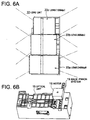
- Figure 6 (a) is embodiment of lens unit that is placed at the best position for avoiding interference between lenses in considering the length of lens pipe and lens diameter in case of lens 22a, 22b and 22c each corresponding to 2400 bpi, 800 dpi and 1200 dpi.
- Figure 6 (b) shows an embodiment of optical unit 15 (see figure 3) on which lens unit shown in figure 6(a).In the embodiment, rack pinion mechanism 19a is used instead of belt 19 of figure 3 as a means for moving the optical unit 15 in a direction along the optical axis.
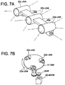
- Figure 7 shows another embodiment of lens unit and figure 7 (a) shows an example of lens unit, in case necessary for enough great pitch between the lenses, and each lens is connected with substrate 40a, 40b of necessary length. Lens is changed by moving the unit in a direction along the lens connections.
- Figure 7 (b) shows an embodiment that each lenses is attached separately on a circular substrate 41, and the circular substrate 41 is rotated by driving motor to change the lenses.
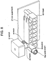
- Figure 8 shows an embodiment of optical unit for CCD substrate 27 in the reading unit of figure 3.
- the example of figure 8 is a rack and pinion being used as the means for moving moves back and forth the optical unit 26 in stead of the belt 32 of figure 3.
- the rack 44 mounted on the frame 43 contacted with the pinion is implemented by the motor 43 to move the CCD substrate 27 fixed to the frame 43 back and forth.
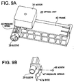
- Figure 9 (a) is that a pressure spring 46 same with the pressure spring 39 of figure 5 being mounted on back to the sleeve 29 for preventing the optical unit vibrating, and the pressure spring 39 is formed to frame 43 as one body forming with resin.
- Figure 9 (b) shows the other example that fixed a pressure spring 47 made by springy metal fixed back to the screw 48 , and a shoe 47a of point part of pressure spring 47 moves the guide shaft 16a inserted to the sleeve 29.
- CCD substrate 27 When CCD substrate 27 is not attached parallel to the manuscript surface or lens plane, resolution of main scanning direction changes, or image forming plane is curved. Therefore it is necessary that CCD substrate 27 is movable independently to left and right in a parallel direction for easily setting up and regulating thereof.
- Figure 10 (a) and (b) shows an embodiment for these.
- Figure 10 (a) shows a cross sectional view of optical unit of frame 43 from upper position and CCD substrate 27 and frame 43 are connected with two slide pin of 49a and 49 b.
- Each of the top of slide pin 49a ,49b is inserted into a hole opened at frame 43 and is possible to slide right and left independently.
- insertion length of the slide pin 49 a and 49b is regulated so that out put of CCD substrate 27 a is uniform and it is fixed to the frame 43.
- Figure 10 (b) shows another embodiment, and it is that the right and left setting hole 51a and 51b for fixing the metal plane part 50 to frame 43 are formed like an oval form, and each of right and left sides is set at the suitable position and fixed by the screw 52a and 52b to the frame 43.
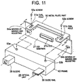
- Figure 11 shows a detail view of figure 10 (b).
- Upper part of the metal substrate 50 coupled with the CCD substrate 27 and ear shaped part are formed right and out side.
- Oblique hole 51a 52b are formed and fixed to the screw hole 53a ,53b opened at the frame 43 each by screw 52a, 52b.
- Further hole 54a,54b penetrates the guide shaft 16a, 16b (see figure 3) at right side and left side of CCD substrate 27.
- Figure 12 shows a cross sectional view of the main frame 11 along the optical axis.
- figure 13 shows an oblique view of the main frame 11 of which frame part 11a of left side keeping mirror 12b ,12c is extracted to show inner partition 11b.
- figure 14 shows a cross sectional view of the main frame 11 cut at line SS-SS of figure 13.As shown apparently by this way, in the main frame 11, the optical axis through and from the mirror 12b, 12c to the optical unit 15 and optical unit 26 is perfectly sheltered against external part without the opening part 11d from which light reflected from the manuscript injects. By this way, optical external disturbance other than light from scanning position of manuscript are cut and a high quality image input is possible.
- Figure 15 shows an embodiment read by a plurality of different resolutions.
- five small size manuscript s 2a ⁇ 2e are stationed on a manuscript platform station.
- Resolution switchover is indicated by block unit in sub-scan direction (or by setting resolution switchover point).
- the embodiment shown in the figure is that the manuscript of first block 2a,2b is 800 dpi the manuscript of second block 2c is 1200dpi, the manuscript of third block 2d is 2400dppi, the forth manuscript of 2e is 800dpi.
- the original reader finds whether there is an indication for the changing resolution or not at each sub-scanning position, and controls switchover of a lens corresponding to the indicated resolution by each time finding in the indication for changing the resolution, and moving the lens unit and the CCD substrate in a direction along the optical axis for regulating magnifying and focusing.
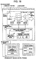
- Figure 16 shows an embodiment which may indicate the switchover of the resolution.
- the original reader of figure 16 comprises the resolution directing means 57 and the resolution switchover control means 58 in the manuscript reading control part.
- the resolution directing means 57 has a table which corresponds the sub-scanning position to be changed the resolution to the resolution, and indicates changing resolution to resolution switchover controlling means, when sub-scan reaches to a sub-scan position to change resolution.
- the resolution switchover control means 58 stops the sub-scan, drives the motor 23, insert the lens of the lens unit 21 into the path of the optical axis, and drives motor 18 and motor 31 to transfer the lens unit 21 and the CCD substrate 27 to a position adaptive for the lens to be used in a direction along the optical axis.
- the resolution is set to the resolution directing means 57.
- pre-scan is operated by control of any one of resolution
- the pre-view image is displayed by image data obtained in the processing device 59 by the operation.
- a different resolution may be set on each region unit by a tool which corresponds each region to the resolution thereof in a direction to the sub-scan region. The set resolution information of region is informed to the original reader 55, and kept by the resolution directing means 57.
- the original reader has a principle structure that changes the specified mono focus lens from plural lenses of different resolutions, and a high effective optical system lower cost than the system using zoom lens is realized.
- the present invention is each of plural lenses being united and the unit is controlled to move so that one of selected lens is transferred into the path of the optical axis, and the lens and the solid-state image sensor (CCD) substrate are regulated independently in a direction to the optical axis direction not only for regulating lens position of the optical axis in the optical path but also regulating optical path length, so both of the resolution and focusing are regulated exactly.
- CCD solid-state image sensor
Landscapes
- Engineering & Computer Science (AREA)
- Multimedia (AREA)
- Signal Processing (AREA)
- Facsimile Scanning Arrangements (AREA)
- Optical Systems Of Projection Type Copiers (AREA)
- Image Input (AREA)
Applications Claiming Priority (3)
| Application Number | Priority Date | Filing Date | Title |
|---|---|---|---|
| JP9163704A JPH1117884A (ja) | 1997-06-20 | 1997-06-20 | 原稿読取装置 |
| JP163704/97 | 1997-06-20 | ||
| PCT/JP1998/002679 WO1998059488A1 (en) | 1997-06-20 | 1998-06-17 | Original reader |
Publications (2)
| Publication Number | Publication Date |
|---|---|
| EP0920183A1 true EP0920183A1 (de) | 1999-06-02 |
| EP0920183A4 EP0920183A4 (de) | 2000-04-19 |
Family
ID=15779048
Family Applications (1)
| Application Number | Title | Priority Date | Filing Date |
|---|---|---|---|
| EP98928531A Ceased EP0920183A4 (de) | 1997-06-20 | 1998-06-17 | Vorlageleser |
Country Status (4)
| Country | Link |
|---|---|
| US (1) | US6424433B1 (de) |
| EP (1) | EP0920183A4 (de) |
| JP (1) | JPH1117884A (de) |
| WO (1) | WO1998059488A1 (de) |
Cited By (1)
| Publication number | Priority date | Publication date | Assignee | Title |
|---|---|---|---|---|
| EP1443745A4 (de) * | 2001-10-10 | 2006-06-07 | Pfu Ltd | Bildlesevorrichtung |
Families Citing this family (18)
| Publication number | Priority date | Publication date | Assignee | Title |
|---|---|---|---|---|
| US6891642B1 (en) * | 1999-07-23 | 2005-05-10 | Matsushita Electric Industrial Co., Ltd. | Apparatus for treating images |
| US6624914B1 (en) * | 2000-03-10 | 2003-09-23 | Hewlett-Packard Development Company, L.P. | Multiple resolution selectable lens scanning system and method |
| US6985177B2 (en) * | 2000-07-04 | 2006-01-10 | Canon Kabushiki Kaisha | Image sensing system and its control method |
| US6639694B1 (en) * | 2000-09-05 | 2003-10-28 | Umax Data Systems Inc. | Imaging apparatus with divers resolution |
| US6678074B1 (en) * | 2000-10-06 | 2004-01-13 | Umax Data Systems, Inc. | Changeable resolution apparatus and method for optical scanner |
| US6674560B2 (en) * | 2001-08-03 | 2004-01-06 | Umax Data Systems, Inc. | Optical lens of optical scanner |
| JP4507495B2 (ja) * | 2003-01-28 | 2010-07-21 | 船井電機株式会社 | 画像読取り装置 |
| JP4806938B2 (ja) * | 2005-03-08 | 2011-11-02 | セイコーエプソン株式会社 | 画像読み取り装置 |
| JP4636246B2 (ja) * | 2005-06-30 | 2011-02-23 | ブラザー工業株式会社 | 画像読取装置 |
| US7612924B2 (en) * | 2005-11-09 | 2009-11-03 | Microtek International Inc. | Carriage module with image capture unit |
| TWI334303B (en) * | 2007-08-10 | 2010-12-01 | Primax Electronics Ltd | Scanner with different resolutions |
| JP4597201B2 (ja) * | 2008-02-29 | 2010-12-15 | 株式会社沖データ | 画像読取装置及び画像読取システム |
| TWM374110U (en) * | 2009-09-21 | 2010-02-11 | Riotec Co Ltd | Bar code scanning device capable of switching reading scan resolution |
| JP6102321B2 (ja) * | 2012-03-01 | 2017-03-29 | 株式会社リコー | 撮像ユニット、測色装置、画像形成装置、測色システムおよび測色方法 |
| JP5845987B2 (ja) * | 2012-03-13 | 2016-01-20 | 株式会社リコー | 撮像装置、撮像システム、測色装置、測色システム及び画像形成装置 |
| US8730543B2 (en) | 2012-06-19 | 2014-05-20 | Xerox Corporation | Detecting common errors in repeated scan workflows by use of job profile metrics |
| US8736929B2 (en) * | 2012-06-19 | 2014-05-27 | Xerox Corporation | Recording and recalling of scan build job and scan batch job settings |
| JP2018037925A (ja) * | 2016-09-01 | 2018-03-08 | セイコーエプソン株式会社 | スキャナー、画像データの生成方法 |
Family Cites Families (21)
| Publication number | Priority date | Publication date | Assignee | Title |
|---|---|---|---|---|
| DE1917139C3 (de) * | 1969-04-02 | 1978-11-30 | Erwin Sick Gmbh Optik-Elektronik, 7808 Waldkirch | Vorrichtung zum Anbringen von photoelektrischen Abtasteinrichtungen an Maschinen |
| JPS5593166A (en) | 1979-01-08 | 1980-07-15 | Matsushita Electric Ind Co Ltd | Copying machine |
| JPS57155868A (en) | 1981-03-23 | 1982-09-27 | Hitachi Ltd | Error current correcting circuit |
| DE3339765A1 (de) | 1983-11-03 | 1985-05-15 | Spiro Research B.V., Helmond | Tragelement fuer aufzuhaengende gegenstaende |
| US4580172A (en) | 1984-07-02 | 1986-04-01 | The Mead Corporation | Optical scanner for automatic document handler |
| US4751376A (en) | 1985-04-12 | 1988-06-14 | Minolta Camera Kabushiki Kaisha | Image reader with focus and magnification detection control |
| JPH01279668A (ja) | 1988-05-02 | 1989-11-09 | Mitsubishi Electric Corp | 原稿静止形画像読取装置 |
| JP2613268B2 (ja) | 1988-07-11 | 1997-05-21 | 関西ペイント株式会社 | 鋼材の水素脆性防止方法及びこの方法によつて得られる鋼材 |
| JPH02155366A (ja) | 1988-12-07 | 1990-06-14 | Nec Corp | 画像読み取り装置 |
| JPH0435455A (ja) | 1990-05-30 | 1992-02-06 | Tokyo Electric Co Ltd | ファクシミリ装置 |
| JPH04160865A (ja) | 1990-10-24 | 1992-06-04 | Sharp Corp | 原稿読取装置付複写機 |
| JPH0698099A (ja) | 1992-09-14 | 1994-04-08 | Mitsubishi Electric Corp | 原稿読取装置 |
| JPH06152857A (ja) | 1992-11-06 | 1994-05-31 | Ricoh Co Ltd | 画像読取装置の光学系調整装置 |
| US5535040A (en) * | 1993-01-12 | 1996-07-09 | Ohtsuka; Tadao | Lens changeable image scanner and lens position control device in the same |
| JP3294710B2 (ja) | 1994-04-28 | 2002-06-24 | 株式会社リコー | 画像読取装置における固体撮像素子の取付方法及び取付構造 |
| JPH0888785A (ja) * | 1994-09-16 | 1996-04-02 | Toshiba Corp | 画像入力装置 |
| US5703729A (en) * | 1994-12-12 | 1997-12-30 | Dainippon Screen Mfg. Co., Ltd. | Image inputting apparatus |
| JPH0970021A (ja) | 1995-09-01 | 1997-03-11 | Noosaido:Kk | 映像送受信装置 |
| JPH118737A (ja) * | 1997-06-17 | 1999-01-12 | Nikon Corp | 画像入力装置、画像入力制御装置および記録媒体 |
| TW383132U (en) * | 1998-07-09 | 2000-02-21 | Microtek Int Inc | Optical path converter |
| US6621603B2 (en) * | 1998-07-20 | 2003-09-16 | Microtek International Inc. | Multi-resolution transmissive and reflective scanner |
-
1997
- 1997-06-20 JP JP9163704A patent/JPH1117884A/ja active Pending
-
1998
- 1998-06-17 US US09/242,638 patent/US6424433B1/en not_active Expired - Fee Related
- 1998-06-17 WO PCT/JP1998/002679 patent/WO1998059488A1/ja not_active Ceased
- 1998-06-17 EP EP98928531A patent/EP0920183A4/de not_active Ceased
Cited By (2)
| Publication number | Priority date | Publication date | Assignee | Title |
|---|---|---|---|---|
| EP1443745A4 (de) * | 2001-10-10 | 2006-06-07 | Pfu Ltd | Bildlesevorrichtung |
| US7327499B2 (en) | 2001-10-10 | 2008-02-05 | Pfu Limited | Image reading apparatus |
Also Published As
| Publication number | Publication date |
|---|---|
| EP0920183A4 (de) | 2000-04-19 |
| US6424433B1 (en) | 2002-07-23 |
| JPH1117884A (ja) | 1999-01-22 |
| WO1998059488A1 (en) | 1998-12-30 |
Similar Documents
| Publication | Publication Date | Title |
|---|---|---|
| US6424433B1 (en) | Original reader | |
| US7471428B2 (en) | Contact image sensor module and image reading device equipped with the same | |
| US6172784B1 (en) | Image reading apparatus | |
| JP2616022B2 (ja) | 画像読取装置 | |
| US5535040A (en) | Lens changeable image scanner and lens position control device in the same | |
| US6603581B2 (en) | High resolution scanner | |
| US5420700A (en) | Image conversion apparatus having scanning mechanism and optical system on single base | |
| US20020140990A1 (en) | Focus calibrating method for image scanning device by testing focus chart | |
| KR100409143B1 (ko) | 화상판독장치및판독방법 | |
| US6233067B1 (en) | Method of and apparatus for reading image by flatbed scanning | |
| JP4798275B2 (ja) | 画像読み取り装置 | |
| EP0896464B1 (de) | Bildlesegerät und Einstellverfahren dafür | |
| JPH03503704A (ja) | 原稿走査用スキャナ | |
| JPH0723180A (ja) | 画像読取り装置 | |
| US6744541B1 (en) | Scanning apparatus for scanning both transparent and reflective objects | |
| US20010013957A1 (en) | High resolution scanner | |
| US6373599B1 (en) | Image scanning apparatus and method | |
| JP2005189341A (ja) | 画像読取装置 | |
| JPH05122451A (ja) | イメージスキヤナ | |
| US7327499B2 (en) | Image reading apparatus | |
| JP4396593B2 (ja) | 画像読み取り装置 | |
| JP2001223843A (ja) | 画像読み取り装置とその画像歪み調整方法 | |
| JP4363160B2 (ja) | 画像読み取り装置及び画像読み取り方法 | |
| JP2000105816A (ja) | 原稿読取装置 | |
| JPH02278963A (ja) | 画像読み取り装置 |
Legal Events
| Date | Code | Title | Description |
|---|---|---|---|
| PUAI | Public reference made under article 153(3) epc to a published international application that has entered the european phase |
Free format text: ORIGINAL CODE: 0009012 |
|
| 17P | Request for examination filed |
Effective date: 19990316 |
|
| AK | Designated contracting states |
Kind code of ref document: A1 Designated state(s): DE FR GB |
|
| A4 | Supplementary search report drawn up and despatched |
Effective date: 20000303 |
|
| AK | Designated contracting states |
Kind code of ref document: A4 Designated state(s): DE FR GB |
|
| STAA | Information on the status of an ep patent application or granted ep patent |
Free format text: STATUS: THE APPLICATION HAS BEEN REFUSED |
|
| 18R | Application refused |
Effective date: 20060216 |