EP0920190B1 - Masquage flou pour rendre d'images numerique en mode brouillon - Google Patents
Masquage flou pour rendre d'images numerique en mode brouillon Download PDFInfo
- Publication number
- EP0920190B1 EP0920190B1 EP98121783A EP98121783A EP0920190B1 EP 0920190 B1 EP0920190 B1 EP 0920190B1 EP 98121783 A EP98121783 A EP 98121783A EP 98121783 A EP98121783 A EP 98121783A EP 0920190 B1 EP0920190 B1 EP 0920190B1
- Authority
- EP
- European Patent Office
- Prior art keywords
- image
- mode
- unsharp mask
- unsharp
- process according
- Prior art date
- Legal status (The legal status is an assumption and is not a legal conclusion. Google has not performed a legal analysis and makes no representation as to the accuracy of the status listed.)
- Expired - Lifetime
Links
Images

Classifications
-
- H—ELECTRICITY
- H04—ELECTRIC COMMUNICATION TECHNIQUE
- H04N—PICTORIAL COMMUNICATION, e.g. TELEVISION
- H04N1/00—Scanning, transmission or reproduction of documents or the like, e.g. facsimile transmission; Details thereof
- H04N1/40—Picture signal circuits
- H04N1/409—Edge or detail enhancement; Noise or error suppression
- H04N1/4092—Edge or detail enhancement
-
- G—PHYSICS
- G06—COMPUTING OR CALCULATING; COUNTING
- G06T—IMAGE DATA PROCESSING OR GENERATION, IN GENERAL
- G06T5/00—Image enhancement or restoration
- G06T5/20—Image enhancement or restoration using local operators
-
- G—PHYSICS
- G06—COMPUTING OR CALCULATING; COUNTING
- G06T—IMAGE DATA PROCESSING OR GENERATION, IN GENERAL
- G06T5/00—Image enhancement or restoration
- G06T5/73—Deblurring; Sharpening
- G06T5/75—Unsharp masking
Definitions
- Unsharp masking is used in photography for highlighting edges of images. To this end, a blurred version of an image is subtracted from the original image to produce an unsharp image model. This mask is then superimposed on the original image to increase the contrast of any abrupt contrast transitions (i.e., edges) within the image. This process can be described by a linear equation: I out ⁇ I in + C ( I in ⁇ I mask )
- GB-A-2 165 717 further improves the method by introducing a plurality of processing parameters.
- edges in an image can be emphasized as well as deemphasized, if desired.
- Parameters can be adjusted, for instance, dependent on the contents of an image, and also color dependent, on a pixel by pixel basis.
- Digital images are composed of discrete tones (e.g., often only black and white pixels), so the perceived quality of these images strongly depends on the human visual response to the printed pixel patterns that define the images.
- continuous tone images are most effectively represented by pixel patterns, such as halftoned pixel patterns which are optimized to create the appearance of smooth, well controlled contrast variations, while line art images, such as text, are better represented by pixel patterns which are optimized to create the appearance of sharp, crisp contrast variations. Therefore, it would be beneficial to be able to dynamically tune a digital unsharp image mask to the type of digital image that is being printed so that edge highlighting of the unsharp mask can be realized without detracting from the perceived quality of digitally printed image as a whole.
- an original image is represented at a suitable resolution, such as 300 dots per inch (d.p.i.) by pixel values (typically 8-bit values) which are serially received in raster scan order (say, left-to-right/top-to-bottom order) from a suitable image input terminal (IIT).
- pixel values typically 8-bit values
- raster scan order say, left-to-right/top-to-bottom order
- IIT image input terminal
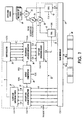
- an image resampling, contextually sensitive smoothing filter 21 for feeding a blurred version of the original image to a low pass filter 22 at the desired output resolution and magnification.
- the low pass filter 22 effectively "differentiates" (i.e., edge enhances) this blurred image by essentially passing black and near black pixel values (i.e., pixels having near 0 values) while transforming all other pixel values toward white (e.g., toward a value of 255). See Fig. 3.
- a summer 23 computes the difference between the original image and the edge enhanced version of the image to provide an unsharp mask of the original image.
- a variable multiplier 24 then weights this unsharp mask in accordance with an adjustable weighting factor F.
- a summer 25 then additively combines this weighted unsharp mask with the original image for rendering of the unsharp masked image at the selected magnification and resolution by a suitable rendering engine 26.
- an SRAM memory 28 functions as a randomly addressable FIFO ring buffer for sharing the pixel values which are needed to compute the blurred and unsharp masked versions of the original image. It has been found that only about five scan lines of context are required to satisfactorily compute the blurred image, so the SRAM 28 is sized accordingly. Data is transferred back and forth between the SRAM 28 and an SRAM interface 29 via a data path SD, and the locations within which these data reads and writes are performed are determined by the addresses carried on an address path SA.
- the smoothing filter 21 is a so-called separable filter having two sections, 31 and 32, one for contextually smoothing the image in the slowscan direction (i.e., the process direction) and the other for contextually smoothing the image in the orthogonal or fast scan direction.
- the original input image first is resampled by a linear interpolator 34 and then is smoothed in the slow scan direction by the first section 31 of the filter 21.
- This provides an intermediate representation of the image, so sufficient context of this intermediate representation to carry out the smoothing of the image in the fast scan direction is stored in a shift register 35 which has an output post from each of its stages.
- the fast scan context that is accumulated by the shift register 35 is resampled by another linear interpolator 36 and then smoothed in the fast scan direction by the second stage 32 of the smoothing filter 21.
- each section of the filter 21 comprises, as shown in Fig. 2, multipiers 61-65 for multiplying the current pixel value and its nearest vertical or horizontal neighbors by weights of 2,2,2,1 and 1, respectively, (or 1,2,2,2,1 as viewed with the filter centered on the current pixel). These weighted pixel values then are summed by summer 67-70. Finally, the aggregate of the sums is divided by the sum of the weights in a divider 71. As is known, multiplying and dividing powers of 2 corresponds to shifts in one direction or the other when implemented in hardware.
- the original image is effectively stepped across the smoothing filter 21 in context and at a desired magnification and resolution.
- the magnification may cause the image to step across the smoothing filter 21 in steps that are not integer multiples of the original scan pitch, so an offset compensator 38 is provided for causing the resampling linear interpolators 34 and 36 to substantially compensate for any displacement of the pixel center positions in the magnified image from the center positions of the corresponding pixels in the original image.
- One additional line of context usually is sufficient to enable the interpolator 34 to perform this compensation in the slow scan direction.
- the interpolator 36 may not only have to compensate for magnification caused pixel center offsets, but may also have to compensate for resolution mismatches (such as when an image that is scanned at 300 d.p.i., is rendered at 600 d.p.i.).
- An image processing pipeline is employed to carry out this invention, so that data is synchronously transferred from step-to-step of the process.
- the registers 41 and 42 through which the blurred and the original image are respectively shifted for computing the unsharp mask and the unsharp masked output image are part of this pipeline.
- the weighting factor F for the unsharp mask is adjustable by varying the multiplication of the multiplier 24.
- This weighting may be dynamically adjusted on, say, a pixel-by-pixel basis in response to, say, a logical image type characterizing signal supplied by an image segmentor (not shown).
- the weighting factor F of the multiplier 24 may be controlled in response to the manual manipulation of a mode switch (also not shown).
- the dynamic and manual control of the weighting factor F may be combined.
- the unsharp mask tends to soften or sharpen the rendered image depending on whether the weighting factor F is less than or greater than 1.
- the weighting factor F may be selected to be about (a) 0.8 for the printing of continuous tone images to cause the unsharp mask to soften the edge detail, (b) 1.2 for the printing of line art images to cause the unsharp mask to enhance the image edges, or (c) 2.0 or higher for draft mode printing to cause the unsharp mask to strongly dominate the rendering in the interest of saving marking material. If the weighting factor F is only manually controllable, it may be set to a value of about 1.0 for a normal print mode and to a value of about 2.0 for a draft or toner/ink saver mode.
- the output pixel values are adjusted to provide the desired tranform function for each selected mode of operation of the rendering engines by a mode dependent look-up table 60.
- a mode dependent look-up table 60 For example, as illustrated in Fig. 3, there is an extreme example of a so-called tone reproduction curve that is characteristic of the toner saver mode of operation.
Landscapes
- Engineering & Computer Science (AREA)
- Physics & Mathematics (AREA)
- General Physics & Mathematics (AREA)
- Theoretical Computer Science (AREA)
- Multimedia (AREA)
- Signal Processing (AREA)
- Image Processing (AREA)
- Facsimile Image Signal Circuits (AREA)
- Preparing Plates And Mask In Photomechanical Process (AREA)
- Editing Of Facsimile Originals (AREA)
Claims (5)
- Procédé de mise en oeuvre d'un moteur qui restitue des images à représentation numérique, comprenant les étapes consistant à :générer un masque flou à représentation numérique d'une telle image ; etcombiner ledit masque flou avec ladite image avec une pondération (F) appliquée audit masque flou ;caractérisé en ce queledit procédé met en oeuvre sélectivement ledit moteur dans un mode de matériau de marquage réduit et dans au moins un autre mode, etqu'il comprend en outre l'étape consistant à fixer ladite pondération (F) pour le masque flou en fonction dudit mode de mise en oeuvre dudit moteur à une valeur relativement élevée pour ledit mode de matériau de marquage réduit et sensiblement plus faible pour ledit autre mode.
- Procédé selon la revendication 1, dans lequel ladite pondération relativement élevée pour ledit mode de matériau de marquage réduit est égale ou supérieure à environ 2,0.
- Procédé selon la revendication 1 ou 2, dans lequel ladite pondération sensiblement plus faible pour ledit autre mode est d'environ 1,0.
- Procédé selon l'une quelconque des revendications 1 à 3, dans lequel l'étape consistant à générer le masque flou à représentation numérique comprend :le lissage de l'image dans une direction de balayage lent afin d'obtenir une représentation intermédiaire ;le lissage de la représentation intermédiaire dans une direction de balayage rapide afin d'obtenir une version floue de l'image ;l'amélioration des bords de ladite version floue par transformation de tous les pixels non noirs en pixels blancs ; etl'obtention du masque flou à représentation numérique en prenant la différence entre la version floue à bords améliorés et l'image.
- Procédé selon l'une quelconque des revendications 1 à 4, comprenant en outre, après ladite étape de combinaison, une étape consistant à régler les valeurs des pixels de sortie selon un tableau de référence (60) dépendant du mode.
Applications Claiming Priority (4)
| Application Number | Priority Date | Filing Date | Title |
|---|---|---|---|
| US97176797A | 1997-11-17 | 1997-11-17 | |
| US971628 | 1997-11-17 | ||
| US08/971,628 US6046821A (en) | 1997-11-17 | 1997-11-17 | Unsharp masking for draft mode rendering of digital images |
| US971767 | 1997-11-17 |
Publications (3)
| Publication Number | Publication Date |
|---|---|
| EP0920190A2 EP0920190A2 (fr) | 1999-06-02 |
| EP0920190A3 EP0920190A3 (fr) | 2000-12-20 |
| EP0920190B1 true EP0920190B1 (fr) | 2006-09-20 |
Family
ID=27130548
Family Applications (1)
| Application Number | Title | Priority Date | Filing Date |
|---|---|---|---|
| EP98121783A Expired - Lifetime EP0920190B1 (fr) | 1997-11-17 | 1998-11-16 | Masquage flou pour rendre d'images numerique en mode brouillon |
Country Status (2)
| Country | Link |
|---|---|
| EP (1) | EP0920190B1 (fr) |
| DE (1) | DE69835931T2 (fr) |
Families Citing this family (2)
| Publication number | Priority date | Publication date | Assignee | Title |
|---|---|---|---|---|
| US7333673B2 (en) * | 2003-10-30 | 2008-02-19 | Samsung Electronics Co., Ltd. | Method and apparatus for image detail enhancement without zigzagged edge artifact |
| RU2445677C1 (ru) | 2010-09-13 | 2012-03-20 | Корпорация "САМСУНГ ЭЛЕКТРОНИКС Ко., Лтд." | Способ черновой печати посредством преобразования растровых изображений в эскизы (варианты) |
Family Cites Families (6)
| Publication number | Priority date | Publication date | Assignee | Title |
|---|---|---|---|---|
| JPS6195669A (ja) * | 1984-10-16 | 1986-05-14 | Dainippon Screen Mfg Co Ltd | 画像処理方法 |
| JPS61230571A (ja) * | 1985-04-05 | 1986-10-14 | Dainippon Screen Mfg Co Ltd | 画像走査装置 |
| JP2620368B2 (ja) * | 1989-04-18 | 1997-06-11 | 富士写真フイルム株式会社 | 画像信号処理方法およびその装置 |
| JP3337173B2 (ja) * | 1994-06-23 | 2002-10-21 | セイコーエプソン株式会社 | 画像形成装置 |
| US5729270A (en) * | 1994-07-27 | 1998-03-17 | Lexmark International, Inc. | Toner conservation by pel modulation with operator control |
| JPH09244475A (ja) * | 1996-03-05 | 1997-09-19 | Canon Inc | 画像出力装置及びその制御方法 |
-
1998
- 1998-11-16 EP EP98121783A patent/EP0920190B1/fr not_active Expired - Lifetime
- 1998-11-16 DE DE69835931T patent/DE69835931T2/de not_active Expired - Lifetime
Also Published As
| Publication number | Publication date |
|---|---|
| EP0920190A2 (fr) | 1999-06-02 |
| EP0920190A3 (fr) | 2000-12-20 |
| DE69835931T2 (de) | 2007-01-04 |
| DE69835931D1 (de) | 2006-11-02 |
Similar Documents
| Publication | Publication Date | Title |
|---|---|---|
| EP0645737B1 (fr) | Unité de filtrage spatial pour l'amélioration adaptative des bords | |
| EP0814431B1 (fr) | Positionnement de caractères avec anticrénelage et précision inférieure au pixel utilisant des techniques de masquage des niveaux de gris | |
| US6606420B1 (en) | Method and apparatus for digital image darkness control in saturated image structures | |
| CN103581637B (zh) | 图像处理设备和图像处理方法 | |
| US6839152B2 (en) | Adaptive filtering method and apparatus for descreening scanned halftoned image representations | |
| US20020118019A1 (en) | Image processing methods and image processing apparatus | |
| EP0407213B1 (fr) | Appareil de traitement d'image | |
| JPH0372778A (ja) | 画像処理装置の領域識別方式 | |
| US5225915A (en) | Image processing with noise enhancing operators for moire reduction and/or random dot generation | |
| JP2003153006A (ja) | 画像処理装置 | |
| JPH113420A (ja) | 順位付けした基調を使用したデジタルハーフトーン処理 | |
| US6983076B2 (en) | Control system for digital de-screening of documents | |
| US4984097A (en) | Halftone reproduction with enhanced gray level reproducibility | |
| US7433084B2 (en) | Digital de-screening technique for scanned documents | |
| US6046821A (en) | Unsharp masking for draft mode rendering of digital images | |
| KR101221343B1 (ko) | 이차원 회색 성분 교체 | |
| US6301395B1 (en) | Image processing apparatus that can appropriately enhance contour of an image | |
| EP0920190A2 (fr) | Masquage flou pour rendre d'images numerique en mode brouillon | |
| EP0917347A2 (fr) | Masquage flou ajustable dynamiquement pour traitement d'image numerique | |
| JPH02244876A (ja) | 画像処理装置の鮮鋭度改善方式 | |
| US6863360B2 (en) | Method for adjusting dot-gain for a halftone binary bitmap | |
| JP2004112728A (ja) | 画像処理装置 | |
| JP2000216994A (ja) | 画像処理装置 | |
| JP3836970B2 (ja) | 画像形成装置 | |
| JP2951972B2 (ja) | 画像処理装置 |
Legal Events
| Date | Code | Title | Description |
|---|---|---|---|
| PUAI | Public reference made under article 153(3) epc to a published international application that has entered the european phase |
Free format text: ORIGINAL CODE: 0009012 |
|
| AK | Designated contracting states |
Kind code of ref document: A2 Designated state(s): DE FR GB |
|
| AX | Request for extension of the european patent |
Free format text: AL;LT;LV;MK;RO;SI |
|
| PUAL | Search report despatched |
Free format text: ORIGINAL CODE: 0009013 |
|
| AK | Designated contracting states |
Kind code of ref document: A3 Designated state(s): AT BE CH CY DE DK ES FI FR GB GR IE IT LI LU MC NL PT SE |
|
| AX | Request for extension of the european patent |
Free format text: AL;LT;LV;MK;RO;SI |
|
| 17P | Request for examination filed |
Effective date: 20010620 |
|
| AKX | Designation fees paid |
Free format text: DE FR GB |
|
| GRAP | Despatch of communication of intention to grant a patent |
Free format text: ORIGINAL CODE: EPIDOSNIGR1 |
|
| GRAS | Grant fee paid |
Free format text: ORIGINAL CODE: EPIDOSNIGR3 |
|
| GRAA | (expected) grant |
Free format text: ORIGINAL CODE: 0009210 |
|
| AK | Designated contracting states |
Kind code of ref document: B1 Designated state(s): DE FR GB |
|
| REG | Reference to a national code |
Ref country code: GB Ref legal event code: FG4D |
|
| REF | Corresponds to: |
Ref document number: 69835931 Country of ref document: DE Date of ref document: 20061102 Kind code of ref document: P |
|
| ET | Fr: translation filed | ||
| PLBE | No opposition filed within time limit |
Free format text: ORIGINAL CODE: 0009261 |
|
| STAA | Information on the status of an ep patent application or granted ep patent |
Free format text: STATUS: NO OPPOSITION FILED WITHIN TIME LIMIT |
|
| 26N | No opposition filed |
Effective date: 20070621 |
|
| REG | Reference to a national code |
Ref country code: FR Ref legal event code: PLFP Year of fee payment: 18 |
|
| PGFP | Annual fee paid to national office [announced via postgrant information from national office to epo] |
Ref country code: DE Payment date: 20151022 Year of fee payment: 18 Ref country code: GB Payment date: 20151027 Year of fee payment: 18 |
|
| PGFP | Annual fee paid to national office [announced via postgrant information from national office to epo] |
Ref country code: FR Payment date: 20151023 Year of fee payment: 18 |
|
| REG | Reference to a national code |
Ref country code: DE Ref legal event code: R119 Ref document number: 69835931 Country of ref document: DE |
|
| GBPC | Gb: european patent ceased through non-payment of renewal fee |
Effective date: 20161116 |
|
| REG | Reference to a national code |
Ref country code: FR Ref legal event code: ST Effective date: 20170731 |
|
| PG25 | Lapsed in a contracting state [announced via postgrant information from national office to epo] |
Ref country code: FR Free format text: LAPSE BECAUSE OF NON-PAYMENT OF DUE FEES Effective date: 20161130 |
|
| PG25 | Lapsed in a contracting state [announced via postgrant information from national office to epo] |
Ref country code: DE Free format text: LAPSE BECAUSE OF NON-PAYMENT OF DUE FEES Effective date: 20170601 Ref country code: GB Free format text: LAPSE BECAUSE OF NON-PAYMENT OF DUE FEES Effective date: 20161116 |