EP0920794A2 - Landwirtschaftliche Maschine - Google Patents
Landwirtschaftliche Maschine Download PDFInfo
- Publication number
- EP0920794A2 EP0920794A2 EP98203577A EP98203577A EP0920794A2 EP 0920794 A2 EP0920794 A2 EP 0920794A2 EP 98203577 A EP98203577 A EP 98203577A EP 98203577 A EP98203577 A EP 98203577A EP 0920794 A2 EP0920794 A2 EP 0920794A2
- Authority
- EP
- European Patent Office
- Prior art keywords
- agricultural machine
- disc
- protrusions
- discs
- recesses
- Prior art date
- Legal status (The legal status is an assumption and is not a legal conclusion. Google has not performed a legal analysis and makes no representation as to the accuracy of the status listed.)
- Withdrawn
Links
- 238000009331 sowing Methods 0.000 claims abstract description 12
- 239000002689 soil Substances 0.000 claims description 12
- 238000000034 method Methods 0.000 claims description 3
- 229910000639 Spring steel Inorganic materials 0.000 claims description 2
- 238000010276 construction Methods 0.000 description 4
- 230000008878 coupling Effects 0.000 description 4
- 238000010168 coupling process Methods 0.000 description 4
- 238000005859 coupling reaction Methods 0.000 description 4
- 230000000694 effects Effects 0.000 description 2
- 210000003608 fece Anatomy 0.000 description 2
- 239000010871 livestock manure Substances 0.000 description 2
- 230000035508 accumulation Effects 0.000 description 1
- 238000009825 accumulation Methods 0.000 description 1
- 230000002411 adverse Effects 0.000 description 1
- 230000003247 decreasing effect Effects 0.000 description 1
- 238000000151 deposition Methods 0.000 description 1
- 239000000463 material Substances 0.000 description 1
- 239000012858 resilient material Substances 0.000 description 1
- 239000007787 solid Substances 0.000 description 1
Images


Classifications
-
- A—HUMAN NECESSITIES
- A01—AGRICULTURE; FORESTRY; ANIMAL HUSBANDRY; HUNTING; TRAPPING; FISHING
- A01C—PLANTING; SOWING; FERTILISING
- A01C5/00—Making or covering furrows or holes for sowing, planting or manuring
- A01C5/06—Machines for making or covering drills or furrows for sowing or planting
- A01C5/062—Devices for making drills or furrows
- A01C5/064—Devices for making drills or furrows with rotating tools
Definitions
- the invention aims at providing an agricultural machine provided with one or more coulters that make a straight furrow and whose discs hardly slip, if at all.
- the discs do not change their angular position relative to each other during rotation, while at least along part of the circumference the protrusions of one disc engage with the recesses of the other disc.
- the ends of the protrusions of one disc extend outwards beyond the outer surface of the other disc.
- the discs are orientated perpendicularly to their respective axes of rotation. This arrangement prevents the discs from swinging.
- the discs are fastened in a simple manner, if, according to a further inventive feature, there is provided on the inside of the disc a bearing house in which there is accommodated a bearing by means of which the disc rotates about a shaft end, said bearing house being fastened to the disc via at least one bolt-and-nut connection.
- the machine For the purpose of fastening the coulter to the agricultural machine, the machine is provided with a projecting tubular element to which the shaft ends for a couple of discs are fitted.
- This tubular element can be used for depositing material, such as seed, in the furrow.
- a scraper device to the projecting element, which scraper device removes soil from the discs on the inside thereof.
- the sowing machine is a pneumatic sowing machine known per se as described in Dutch patent application 9 500 335.
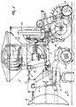
- the sowing machine has a hopper 11 and a conducting tube 12 via which, by an airflow produced by a ventilator 13, seed is passed through lines 14 to a number of coulters 15 which are arranged in a row transversely to the direction of travel A.
- the sowing machine comprises a beam 16.
- This beam which extends horizontally and transversely to the direction of travel A, can be adjusted in vertical height in a manner known per se.
- On this beam there are disposed a number of coulters 15 arranged in side-by-side relationship in such a manner that behind the machine, seen in the direction of travel, seed can be deposited in the soil in a number of furrows.
- a projecting element hereinafter called a seed pipe 21, can be fitted to the beam 16, more in particularly to a bracket 17 which is fastened to the beam 16 by means of a projection 18, a bolt 19 and a clamping plate 20.
- a fastening portion 22 is welded to the seed pipe 21, said fastening portion 22 being disposed on the bracket 17 by means of a bolt-and-nut connection 23.
- the seed pipe 21 comprises a bend 24 and a portion 25 that is orientated straight downwardly, the latter portion having an outlet opening 26.
- This outlet opening 26 is orientated rearwardly and obliquely to such an extent that, seen in the direction of travel A, it is located behind the front side of the seed pipe 21.
- the coulter 15 comprises two discs 35 and 36. These discs are freely rotatable about the shaft ends 31, 32 respectively and are provided for the purpose with bearings 37, 38 respectively. Bearing houses 39, 40 respectively, in which the bearings are accommodated, are fitted to the discs by means of bolt-and-nut connections 41 of which only one is shown in the drawings.
- the shaft ends 31 and 32 are perpendicular to the centre of the round discs 35 and 36, the arrangement being such that upon rotation of the discs the latter remain in the same plane.
- the discs 35 and 36 are concave, their concave sides facing each other.
- the curvature radius of these concave sides is preferably between 450 mm and 600 mm and amounts in this embodiment to 540 mm.
- the outer edges of the discs comprise equally shaped protrusions 42 and equally shaped recesses 43 located therebetween.
- the protrusions and recesses of both discs are identical.
- the shape of the protrusions 42 and the recesses 43 is predominantly rectangular.
- the lateral sides 44 and 45 are orientated radially, which is also the case with the lateral sides of the recesses.
- the protrusions of one disc and the recesses of the other disc fit together with some clearance, the arrangement being such that upon rotation of the discs consecutively other protrusions and recesses engage with each other.
- the lateral sides 44 and 45 of the protrusions 42 have preferably a length of approximately 1 cm.
- the combination of the specifically concave shape of the discs 35, 36 and the shape of the protrusions 42 and the recesses 43 contributes to a proper closing of the recesses thus preventing soil from sticking thereto.
- the outer edges 46 of the protrusions 42 are located on a circle around the centre lines 33, 34 respectively.
- the number of protrusions and consequently the number of recesses of the discs preferably amounts to 15. However, this amount may be somewhat greater or smaller. In this embodiment the diameter of the discs is 30 cm.
- the protrusions and recesses fit together through an angle ⁇ shown in Figure 2.
- This angle is orientated downwardly in the direction of travel and begins near the lower side of the discs.
- the angle ⁇ is preferably 60°, as shown in this embodiment, but a deviation of e.g. 10° is possible as well.
- the coulters 15 can be adjusted at different depths. This takes place by a pivoting movement of the seed pipes 21 about the bolt 23.
- the machine comprises non-shown means to fix the coulters in the desired position.
- the pivoting movement of a seed pipe 21 changes the position of the sector ⁇ through which the protrusions and recesses engage with each other and are in contact with each other.
- a projecting portion 47 To the rear side of the downwardly orientated portion 25 of the seed pipe 21 there is welded a projecting portion 47 to which a V-like strip 48 of resilient material, preferably of spring steel, is fastened (Figure 4).
- This V-like strip 48 serves as a scraper for the inner sides of the concave discs 35 and 36. Fastening of the strip 48 to the projecting portion 47 takes place by means of a bolt 49 fitted to the strip and a nut 50 disposed on the upper side of the strip.
- the strip 48 scrapes with its lower sides serving as scraper faces 51 and 52 against the inner sides of the discs 35, 36 respectively.
- the pressure of the scraper faces 51, 52 on the inner walls can be increased or decreased and also in case of wear of the resilient strip the scraper faces can be readjusted.
- the scraper faces 51, 52 are preferably located at the rear sides of the discs in such a manner that, upon upward rotation of the rear sides of the discs, the earth is scraped therefrom.
- the coulter 15 operates as follows.
- the rotary harrow 2 works the soil which is levelled by the roller 7, during which process also relatively large clods are crumbled. Then the sowing machine 3 deposits seed in the furrows made by the coulters 15.
- the coulters 15 ensure a suitably made furrow at the desired depth.
- the furrow should have an equally worked shape; moreover it is desirable that the furrow contains a minimum of loose clods. Furthermore a regular rotation of the discs of the coulter 15 is desired.
- soil is prevented from remaining between the engaging recesses and protrusions and from impeding the rotating movement of the coulters.
- the V-like strip 48 with its scraper faces 51, 52 contributes to the inner side of the discs remaining clean, which is important for a proper rotation of the discs.
- the construction according to the invention can also be used for coulters to be applied for other purposes, such as coulters for manure injectors. Also in this situation it is desirable to make proper furrows in which manure is deposited instead of seed.
- the machine has one row of coulters. However, the machine may also comprise several rows of coulters.
- the invention does not only relate to the agricultural machine but also to the coulters with seed pipes and to a method of applying coulters.
- the invention is not limited to what has been described in the foregoing but also relates to all the details of the drawings. The invention further relates to all sorts of alternatives in the construction.
Landscapes
- Life Sciences & Earth Sciences (AREA)
- Soil Sciences (AREA)
- Environmental Sciences (AREA)
- Sowing (AREA)
- Soil Working Implements (AREA)
Applications Claiming Priority (2)
| Application Number | Priority Date | Filing Date | Title |
|---|---|---|---|
| NL1007375A NL1007375C2 (nl) | 1997-10-28 | 1997-10-28 | Landbouwmachine. |
| NL1007375 | 1997-10-28 |
Publications (2)
| Publication Number | Publication Date |
|---|---|
| EP0920794A2 true EP0920794A2 (de) | 1999-06-09 |
| EP0920794A3 EP0920794A3 (de) | 2002-02-13 |
Family
ID=19765908
Family Applications (1)
| Application Number | Title | Priority Date | Filing Date |
|---|---|---|---|
| EP98203577A Withdrawn EP0920794A3 (de) | 1997-10-28 | 1998-10-23 | Landwirtschaftliche Maschine |
Country Status (2)
| Country | Link |
|---|---|
| EP (1) | EP0920794A3 (de) |
| NL (1) | NL1007375C2 (de) |
Cited By (3)
| Publication number | Priority date | Publication date | Assignee | Title |
|---|---|---|---|---|
| EP2422599A1 (de) * | 2010-08-31 | 2012-02-29 | Amazonen-Werke H. Dreyer GmbH & Co. KG | Doppelscheibenschar |
| CN108848775A (zh) * | 2018-09-17 | 2018-11-23 | 吉林大学 | 一种实时可调控式双层仿生缺口圆盘开沟器 |
| US11944025B2 (en) * | 2019-05-22 | 2024-04-02 | Osmundson Mfg. Co. | Agricultural drill/planter/coulter/disc blade with step plane notch edge |
Family Cites Families (6)
| Publication number | Priority date | Publication date | Assignee | Title |
|---|---|---|---|---|
| US4337835A (en) * | 1981-01-23 | 1982-07-06 | Deere & Company | Scraper for double disk furrow opener |
| US4598654A (en) * | 1981-12-31 | 1986-07-08 | Acra-Plant, Inc. | Furrow opener and follower blade |
| AP228A (en) * | 1990-09-25 | 1992-12-19 | Tinto Industries Ltd | Star wheel seed planter. |
| DE9219030U1 (de) * | 1992-07-22 | 1997-01-23 | Accord-Landmaschinen Heinrich Weiste & Co., Gesellschaft mit beschränkter Haftung, 59494 Soest | Zweischeibenschar mit Topfscheibe |
| US5346020A (en) * | 1992-08-04 | 1994-09-13 | Bassett James H | Forged clearing wheel for agricultural residue |
| DE19541874C2 (de) * | 1995-11-09 | 1999-02-18 | Kleine Franz Maschf | Sägerät, insbesondere für die Mulch- und/oder Direktsaat |
-
1997
- 1997-10-28 NL NL1007375A patent/NL1007375C2/nl not_active IP Right Cessation
-
1998
- 1998-10-23 EP EP98203577A patent/EP0920794A3/de not_active Withdrawn
Cited By (4)
| Publication number | Priority date | Publication date | Assignee | Title |
|---|---|---|---|---|
| EP2422599A1 (de) * | 2010-08-31 | 2012-02-29 | Amazonen-Werke H. Dreyer GmbH & Co. KG | Doppelscheibenschar |
| CN108848775A (zh) * | 2018-09-17 | 2018-11-23 | 吉林大学 | 一种实时可调控式双层仿生缺口圆盘开沟器 |
| US11944025B2 (en) * | 2019-05-22 | 2024-04-02 | Osmundson Mfg. Co. | Agricultural drill/planter/coulter/disc blade with step plane notch edge |
| US12446481B2 (en) | 2019-05-22 | 2025-10-21 | Osmundson Mfg. Co. | Agricultural drill/planter/coulter/disc blade with step plane notch edge |
Also Published As
| Publication number | Publication date |
|---|---|
| EP0920794A3 (de) | 2002-02-13 |
| NL1007375C2 (nl) | 1999-05-10 |
Similar Documents
| Publication | Publication Date | Title |
|---|---|---|
| US4760806A (en) | Conservation opener | |
| US11716923B2 (en) | Row cleaner/closing wheel | |
| US10555452B2 (en) | Row cleaner/closing wheel | |
| US10060467B2 (en) | Seed planter with equalizer assembly | |
| US20220007568A1 (en) | Press wheel with angled tines | |
| US12305695B2 (en) | Seed planter with equalizer assembly | |
| CA2194731A1 (en) | Seed drill with scraper/soil firming attachment | |
| US7775293B2 (en) | Furrow closer | |
| US9232689B2 (en) | Seed planter with equalizer assembly | |
| US20080066662A1 (en) | Novel gauge wheel for use with a conventional row planter assembly | |
| CN105165187B (zh) | 仿生曲面圆盘施肥开沟器 | |
| US6874584B2 (en) | Disc furrow opener scraper positioning system | |
| JP2004298028A (ja) | 施肥播種機 | |
| EP0920794A2 (de) | Landwirtschaftliche Maschine | |
| US10426076B1 (en) | Depth wheels | |
| US7143837B2 (en) | Soil conditioning rotary reel for secondary tillage operations | |
| EP0150080B1 (de) | Bodenbearbeitungsgeräte | |
| US7143836B2 (en) | Soil conditioning rotary reel for primary tillage operations | |
| RU2731049C1 (ru) | Гребневая сеялка | |
| RU2734481C1 (ru) | Гребневая сеялка | |
| US1170696A (en) | Disk drill. | |
| GB2041202A (en) | Disc tiller blades | |
| RU2819433C1 (ru) | Сошник с крыльчатками для сеялки | |
| RU2730617C1 (ru) | Гребневая сеялка | |
| RU2728602C1 (ru) | Гребневая сеялка |
Legal Events
| Date | Code | Title | Description |
|---|---|---|---|
| PUAI | Public reference made under article 153(3) epc to a published international application that has entered the european phase |
Free format text: ORIGINAL CODE: 0009012 |
|
| AK | Designated contracting states |
Kind code of ref document: A2 Designated state(s): AT BE CH CY DE DK ES FI FR GB GR IE IT LI LU MC NL PT SE Kind code of ref document: A2 Designated state(s): AT DE FR GB IT NL |
|
| AX | Request for extension of the european patent |
Free format text: AL;LT;LV;MK;RO;SI |
|
| PUAL | Search report despatched |
Free format text: ORIGINAL CODE: 0009013 |
|
| AK | Designated contracting states |
Kind code of ref document: A3 Designated state(s): AT BE CH CY DE DK ES FI FR GB GR IE IT LI LU MC NL PT SE |
|
| AX | Request for extension of the european patent |
Free format text: AL;LT;LV;MK;RO;SI |
|
| AKX | Designation fees paid |
Free format text: AT DE FR GB IT NL |
|
| STAA | Information on the status of an ep patent application or granted ep patent |
Free format text: STATUS: THE APPLICATION IS DEEMED TO BE WITHDRAWN |
|
| 18D | Application deemed to be withdrawn |
Effective date: 20020814 |