EP0920887B1 - Jambière avec stabilisation de la cheville - Google Patents
Jambière avec stabilisation de la cheville Download PDFInfo
- Publication number
- EP0920887B1 EP0920887B1 EP97119249A EP97119249A EP0920887B1 EP 0920887 B1 EP0920887 B1 EP 0920887B1 EP 97119249 A EP97119249 A EP 97119249A EP 97119249 A EP97119249 A EP 97119249A EP 0920887 B1 EP0920887 B1 EP 0920887B1
- Authority
- EP
- European Patent Office
- Prior art keywords
- foot
- ankle
- traction
- shin
- lower leg
- Prior art date
- Legal status (The legal status is an assumption and is not a legal conclusion. Google has not performed a legal analysis and makes no representation as to the accuracy of the status listed.)
- Expired - Lifetime
Links
- 210000002683 foot Anatomy 0.000 claims description 255
- 230000033001 locomotion Effects 0.000 claims description 96
- 210000003423 ankle Anatomy 0.000 claims description 74
- 230000006378 damage Effects 0.000 claims description 29
- 208000027418 Wounds and injury Diseases 0.000 claims description 23
- 208000014674 injury Diseases 0.000 claims description 23
- 230000006641 stabilisation Effects 0.000 claims description 13
- 239000000463 material Substances 0.000 claims description 10
- 239000004753 textile Substances 0.000 claims description 7
- 230000000670 limiting effect Effects 0.000 claims description 6
- 238000012546 transfer Methods 0.000 claims description 5
- 229920001971 elastomer Polymers 0.000 claims description 3
- 229920002379 silicone rubber Polymers 0.000 claims description 3
- 239000004945 silicone rubber Substances 0.000 claims description 3
- 230000007704 transition Effects 0.000 claims description 3
- 230000003313 weakening effect Effects 0.000 claims 1
- 210000001699 lower leg Anatomy 0.000 description 65
- 210000001503 joint Anatomy 0.000 description 20
- 210000002414 leg Anatomy 0.000 description 16
- 230000001681 protective effect Effects 0.000 description 16
- 210000002303 tibia Anatomy 0.000 description 14
- 230000001012 protector Effects 0.000 description 12
- 238000011105 stabilization Methods 0.000 description 11
- 230000001965 increasing effect Effects 0.000 description 8
- 210000000544 articulatio talocruralis Anatomy 0.000 description 7
- 238000012549 training Methods 0.000 description 7
- 230000005540 biological transmission Effects 0.000 description 6
- 230000006870 function Effects 0.000 description 5
- 210000003041 ligament Anatomy 0.000 description 5
- 208000022542 ankle injury Diseases 0.000 description 4
- 230000015572 biosynthetic process Effects 0.000 description 4
- 230000003387 muscular Effects 0.000 description 4
- 230000009993 protective function Effects 0.000 description 4
- 238000013461 design Methods 0.000 description 3
- 239000013013 elastic material Substances 0.000 description 3
- 210000003205 muscle Anatomy 0.000 description 3
- 230000011514 reflex Effects 0.000 description 3
- 206010061223 Ligament injury Diseases 0.000 description 2
- 230000008901 benefit Effects 0.000 description 2
- 238000006243 chemical reaction Methods 0.000 description 2
- 239000002131 composite material Substances 0.000 description 2
- 230000003247 decreasing effect Effects 0.000 description 2
- 238000006073 displacement reaction Methods 0.000 description 2
- 230000000694 effects Effects 0.000 description 2
- 230000008407 joint function Effects 0.000 description 2
- 230000004807 localization Effects 0.000 description 2
- 239000004033 plastic Substances 0.000 description 2
- 230000003449 preventive effect Effects 0.000 description 2
- 230000002829 reductive effect Effects 0.000 description 2
- 230000035939 shock Effects 0.000 description 2
- 230000000472 traumatic effect Effects 0.000 description 2
- 208000027502 Ankle fracture Diseases 0.000 description 1
- 206010017076 Fracture Diseases 0.000 description 1
- 206010060820 Joint injury Diseases 0.000 description 1
- 206010061363 Skeletal injury Diseases 0.000 description 1
- 210000001361 achilles tendon Anatomy 0.000 description 1
- 230000009471 action Effects 0.000 description 1
- 230000006978 adaptation Effects 0.000 description 1
- 230000001070 adhesive effect Effects 0.000 description 1
- 238000013459 approach Methods 0.000 description 1
- 230000008878 coupling Effects 0.000 description 1
- 238000010168 coupling process Methods 0.000 description 1
- 238000005859 coupling reaction Methods 0.000 description 1
- 238000011161 development Methods 0.000 description 1
- 230000000763 evoking effect Effects 0.000 description 1
- 210000003108 foot joint Anatomy 0.000 description 1
- 210000004744 fore-foot Anatomy 0.000 description 1
- 230000009931 harmful effect Effects 0.000 description 1
- 210000004124 hock Anatomy 0.000 description 1
- 230000006872 improvement Effects 0.000 description 1
- 230000005764 inhibitory process Effects 0.000 description 1
- 238000003780 insertion Methods 0.000 description 1
- 230000037431 insertion Effects 0.000 description 1
- 230000003993 interaction Effects 0.000 description 1
- 230000014759 maintenance of location Effects 0.000 description 1
- 239000000203 mixture Substances 0.000 description 1
- 230000008092 positive effect Effects 0.000 description 1
- 230000009023 proprioceptive sensation Effects 0.000 description 1
- 239000011359 shock absorbing material Substances 0.000 description 1
Images



Classifications
-
- A—HUMAN NECESSITIES
- A63—SPORTS; GAMES; AMUSEMENTS
- A63B—APPARATUS FOR PHYSICAL TRAINING, GYMNASTICS, SWIMMING, CLIMBING, OR FENCING; BALL GAMES; TRAINING EQUIPMENT
- A63B71/00—Games or sports accessories not covered in groups A63B1/00 - A63B69/00
- A63B71/08—Body-protectors for players or sportsmen, i.e. body-protecting accessories affording protection of body parts against blows or collisions
- A63B71/12—Body-protectors for players or sportsmen, i.e. body-protecting accessories affording protection of body parts against blows or collisions for the body or the legs, e.g. for the shoulders
- A63B71/1225—Body-protectors for players or sportsmen, i.e. body-protecting accessories affording protection of body parts against blows or collisions for the body or the legs, e.g. for the shoulders for the legs, e.g. thighs, knees, ankles, feet
-
- A—HUMAN NECESSITIES
- A63—SPORTS; GAMES; AMUSEMENTS
- A63B—APPARATUS FOR PHYSICAL TRAINING, GYMNASTICS, SWIMMING, CLIMBING, OR FENCING; BALL GAMES; TRAINING EQUIPMENT
- A63B71/00—Games or sports accessories not covered in groups A63B1/00 - A63B69/00
- A63B71/08—Body-protectors for players or sportsmen, i.e. body-protecting accessories affording protection of body parts against blows or collisions
- A63B71/12—Body-protectors for players or sportsmen, i.e. body-protecting accessories affording protection of body parts against blows or collisions for the body or the legs, e.g. for the shoulders
- A63B71/1225—Body-protectors for players or sportsmen, i.e. body-protecting accessories affording protection of body parts against blows or collisions for the body or the legs, e.g. for the shoulders for the legs, e.g. thighs, knees, ankles, feet
- A63B2071/1258—Body-protectors for players or sportsmen, i.e. body-protecting accessories affording protection of body parts against blows or collisions for the body or the legs, e.g. for the shoulders for the legs, e.g. thighs, knees, ankles, feet for the shin, e.g. shin guards
-
- A—HUMAN NECESSITIES
- A63—SPORTS; GAMES; AMUSEMENTS
- A63B—APPARATUS FOR PHYSICAL TRAINING, GYMNASTICS, SWIMMING, CLIMBING, OR FENCING; BALL GAMES; TRAINING EQUIPMENT
- A63B71/00—Games or sports accessories not covered in groups A63B1/00 - A63B69/00
- A63B71/08—Body-protectors for players or sportsmen, i.e. body-protecting accessories affording protection of body parts against blows or collisions
- A63B71/12—Body-protectors for players or sportsmen, i.e. body-protecting accessories affording protection of body parts against blows or collisions for the body or the legs, e.g. for the shoulders
- A63B71/1225—Body-protectors for players or sportsmen, i.e. body-protecting accessories affording protection of body parts against blows or collisions for the body or the legs, e.g. for the shoulders for the legs, e.g. thighs, knees, ankles, feet
- A63B2071/1283—Body-protectors for players or sportsmen, i.e. body-protecting accessories affording protection of body parts against blows or collisions for the body or the legs, e.g. for the shoulders for the legs, e.g. thighs, knees, ankles, feet for the foot
Definitions
- the invention relates to a shin guards, in particular football shin guards, with ankle stabilization.
- Shin guards In the football game, players usually call "shin guards" (Tibia saver), wearing a tibial shield to the Covering at least a lower portion of the lower leg of the Shin guards bearing athlete (wearer) have forward.
- the shin guard is placed on the tibia and by a normal stocking worn over it in his Position held.
- Shin guards are also known, on whose lower end of a stocking with open toe part is attached, the one To prevent slippage of the shield.
- Shin guards with an outside to be placed on the stocking Shield which at its lower end a textile sleeve part having. The textile sleeve part is provided to the lower leg in the transition area to the foot to embrace.
- One on the shield attached band serves to encompass the lower leg and thereby keeping the shield on the lower leg.
- a foot engaging Band provided.
- the known Shin guards have an ankle support section (ankle supporting portion 7), which is designed to protect the ankle (and thus the ankle joint) to support against inversion and eversion and to protect against shocks.
- the ankle support portion has an inner side and an outer side (sides 8) on, which by means of fastening straps (securing straps 3) tight fitting to be secured at the respective ankle.
- fastening straps securing straps
- U-shaped support U-shaped support
- EP-0 552 804 A1 is a shin guards with a pillow-like Shin protection shield known, in addition, a back cushion-like Protective element which serves to protect the Achilles tendon.
- a To provide shin guards according to the preamble of claim 1, the performs an injury avoiding ankle stabilization function or at least one of which interacts with shin guards Football players or other athletes or persons who Use of low shoes while ensuring a preventive To provide ankle stabilization.
- a invention Shin guards proposed with the features of claim 1, as well as a shin guards shoe combination with the features of claim 2.
- the known schienbeinschoner necessary to prevent the shin guards from sliding up, is the shield in the tibia saver invention non-positively fixable on the lower leg. This can be about the at least one tensile element tensile forces and optionally compressive forces from Foot or shoe on the shield and from this to the next Transmitted lower leg and introduced into this.
- the at least one tension element is designed in such a way and arranged that the tensile force transmission according to the invention and optionally Pressure transmission between protective shield (and thus lower leg) on the one hand and shoe and / or foot on the other hand the mobility of the foot relative to the lower leg so limited that the risk of Injuries due to at least one violent movement type is at least substantially reduced.
- mobility foot is, for example, limiting or / and at least for large movement amplitudes - the slowing / aggravating the at least one violent movement type, in particular an inversion / supination movement and / or an Eversions- / Pronationsterrorism of the foot, to understand.
- inversion / supination movements and Eversions- / Pronationsmony of the foot are relatively severely injured. It are the following movements of the foot relative to Lower leg: During pronation, there is an outward turn of the foot (Lifting the outer and lowering the inner foot edge) around a occidentallteilsachse instead of. As a supination, an inward turn (lowering of the outer and lifting the inner foot edge) about the tilllticiansachse.
- inversion refers to a composite movement of one Supination movement and a so-called adduction movement and a so-called plantarflexion movement.
- the plantarflexion designates a pivotal movement of the foot about the approximately transverse Axis of the upper ankle, in which the back of the foot of the Lower leg front removed.
- the Eversionsschi is also a composite movement, the from the mentioned pronation movement as well as a so-called Abduction movement and a so-called Dorsalflexionshab composed.
- abduction movement the foot rotates turn around the already mentioned vertical axis, but now with one Movement of the toe away from the plane of symmetry in the lateral direction.
- Dorsalflexionshab the foot pivots about the said approximately transverse axis in the opposite direction Plantarflexion, so that the back of the lower leg front surface approaches.
- a first axis is the axis of the upper one Ankle joints that are approximately transversal through the inner and the outer ankle of the foot runs, so according to the light Offset of the two ankle in crizoscardi (the foot inside Ankle is opposite the foot outside-ankle in the foot longitudinal direction shifted forward) slightly obliquely from lateral (foot outside) behind to medial (foot inside) front.
- the second, the mobility of the foot relative to the lower leg substantially characterizing axis is the so-called “Henkesche axis", obliquely from lateral (foot outside) behind bottom to medial (Fußinnensch) front top runs and with the called axis of the upper ankle a kind of heterokinetic Cardan joint forms.
- the shin protector is now designed to be alone or in interaction with a shoe at least one injury Type of movement of the foot relative to the lower leg, in particular the called inversion and / or supination and / or pronation and / or Eversion, in the sense cited and, for example, excessive external forces, such as due to accidental kinking of the Foot, at least as far as intercept and past the upper ankle joint into the lower leg that the risk of injury, at least is significantly reduced.
- the muscular apparatus Muscle strength is generally strong enough, even strong to absorb external traumatic forces.
- the muscular apparatus But needs a certain amount of time, for example about 50 ms, to appropriate Build up opposing forces. External forces then become special dangerous if this happens within a shorter period of time, for example 30 ms, so that the muscles can not react fast enough. In such external forces, which in terms of their strength by the Musculature can be intercepted, but rise too fast when that the musculature could follow this increase and that is why It is enough to cause injury to the injured To slow movements to such an extent that the musculature increases can follow the external forces.
- tibia saver invention alone or together with other components, in particular a Shoe, for a corresponding slowing of excessive relative movements Between the foot and lower leg, natural reflexes can help Accidents would often come too late, now be timely and one Prevent injury.
- a violent movement type needs so not in its amplitude of motion absolutely (in the sense of a stop) but it is sufficient if these - at least for large Movement amplitudes - slowed down, for example, by providing corresponding counterforces to aggravate the movement.
- particularly large external forces affecting the muscular retention and the ligament apparatus but it may be useful, even one absolute limitation of the movement amplitude in the sense of a stop provided.
- the tension elements with one in one or the shoe can be taken up between the sole of the foot and the shoe sole, the foot under cross-bottom element of the tibia saver be connected to at least tensile forces between lower gripping element and Protective shield to transfer.
- the lower gripping element can on the shoe, in particular at the shoe sole, be fixable, for example by means of Velcro sections.
- the shoe associated with the shin guard to include in the power transmission chain, the shoe optionally can perform a function corresponding to the sub-gripping element.
- the tension element or the tension elements with the shoe, in particular a shoe side portion of the shoe, connected or be connectable is also possible.
- a Limitation of the mobility of the foot relative to Lower leg can be achieved in the illustrated sense.
- a particularly effective protective effect of the shin guards against the aforementioned injury risks, in particular of the upper ankle is achieved in that the fußau dry mixede joint is offset forward of the outer ankle, preferably so far, that the fußau dry mixede joint against a Middle position between the inner and outer ankle forward is offset.
- This can be achieved in that one or the leg portion of the foot outer side tension member relative to the outer Ankle is offset forward, preferably so far that the leg portion opposite the middle position between the inner and outer Ankle is offset to the front.
- the present invention additionally provided reshuffling of the foot inside Joint behind the inner ankle, preferably opposite the center position to the rear, the risk of Pronation damage or damage to the skin, in particular fractures of the Lateral malleolus.
- a pronation movement namely forces are increasingly on the foot inside tension element from the sole of the foot to the protective shield and Accordingly transferred to the lower leg, with a corresponding Deceleration and a corresponding restriction of the other Eversion or pronation movement of the foot.
- one or the leg portion of the foot inside Tension element opposite the inner ankle preferably opposite to the Middle position, offset to the rear.
- the foot outside hinge opposite the foot inside joint in foot longitudinal direction is offset to the front. This can be done, for example be achieved, that a leg portion of the foot outside tension member against a leg portion of the foot inside Tension element is offset in the foot longitudinal direction to the front.
- the outer pan or Movement axis runs more or less depending on the size of the offset transverse to the movement of the tarsal root below the upper ankle joint characterizing Henkeschen axis.
- the foot also rotates about the Henkesche axis, but by the (otherwise, possibly oriented transversely to the Henkian axis) outer swivel or movement axis increasingly braked, possibly is blocked. Due to the basic elasticity of the shin guards and / or the associated shoe is initially in spite of the different Movement axes of foot on the one hand and shin guards or shoe On the other hand, an inversion or Eversionsterrorism the foot possible. Increasingly, however, this movement is due to the shin guards, optionally in conjunction with the shoe, inhibited.
- the full Agility of the foot is according to the described development of Invention thus not intended to damage the foot, in particular the ankle and ligaments, to the extent possible exclude.
- a Joint or / and one or the leg portion of a tension element on the one hand by a Joint or / and one or the leg portion of a tension element and, on the other hand, either through a center of a link between the outer and inner knuckles or through the other Joint and / or one or the leg portion of a Tension element on the other foot side going straight line and a Foot transverse axis in projection on one to the foot transverse axis and to the foot longitudinal axis parallel horizontal plane an angle ⁇ of at least 10 °, preferably at least 15 °, more preferably at least 20 °, most preferably at least 30 °.
- the specified Link is generally associated with the relative mobility between shield or lower leg on the one hand and foot or shoe on the other hand characterizing "outer" pivot or movement axis coincide, so that the above statements can be referenced.
- the inhibition of inversion or conversion movements sets accordingly with increasing Angle ⁇ already for smaller movement amplitudes.
- the Angle ⁇ does not exceed an angle of 80 °; as is preferred for the angle ⁇ proposed an upper limit of about 45 °.
- At least one of the tension members may have a lower and an upper one Gebelementabites, in particular a lower and an upper Leg section, which are connected via a hinge. At least one joint can with in the be formed substantially vertical joint play.
- the training of the joint as Hinge pin-AusBackungskombination, as hinge joint, as material attenuation (In particular film hinge), as Switzerlandelementabêt with opposite the other tension element other material (in particular softer and / or more elastic material) or as a bellows section called.
- At least one of the tension elements can at least partially elastic, in particular be designed as zugelasticians band.
- the elastic training of the tension element can be achieved in particular that a deceleration of a limited Moving scenery not suddenly, as when using a joint with hinge pins in one Slot and at the same time inelastic tension element, uses, but that the movement limiting opposing forces with increasing movement amplitude gradually increase.
- This will be a particularly high Comfort as well as appropriate for the respective sport Mobility achieved, in particular due to easier mobility with some adaptation of the outer movement axis to the respective Wear the shin guards and especially because of the avoidance jerky decelerations.
- the respective at least one tension element in particular of the elastic band such that the tensile force exerted on stretching (Drag) increases linearly with the strain, also comes an education such that the tensile force increases progressively with the elongation.
- the at least one tension element or the Toughened band a progressively decreasing tensile elasticity when stretched exhibit.
- the other Pronation movement (Eversionsschi) or supination movement (Inversion movement) decelerating and restricting opposing forces in may be relatively low in an initial region and then in the course of further movement, for example, increase exponentially, so on the one hand through the initial area with the low counter forces a particularly undisturbed mobility with certain customization options outer axis of movement to the respective tibial protector given by the progressively increasing opposing forces a violent movement beyond the starting area reliably avoided without a sudden deceleration of the Movement occurs.
- a forgiving Bands can vary the tensile elasticity in the belt longitudinal direction, in particular to provide a spatially well-defined zone, which the Joint function takes over and therefore as joint in the sense to claim the invention.
- the material for the elastic band is rubber or / and silicone rubber into consideration.
- the tension elements and - in the case of the shin guards according to claim 1 - optionally the lower gripping element can be integral with the protective shield, in particular one-piece, be trained.
- the shin guards By a one-piece training is the shin guards especially inexpensive to produce.
- the shin guards can have at least one - known "knuckle protection shield", preferably from a foot inside or fußau to solution element is held and optionally integral with these, in particular one-piece, is formed.
- the holding means for non-positive fixing of the protective shield on Lower legs can offset two in height direction, zugelastician and preferably adjustable straps comprise, the optionally a closure, in particular Velcro fastener having.
- For non-positive fixing of the shield can also be attached to the Shape of the lower leg adapted inner surface and / or the Properties (adhesive properties, coefficient of friction) of the lower leg contribute to the adjacent material of the protective shield; the inner surface or the material applied to the lower leg can insofar the attributed holding means.
- the shin guards a the lower leg especially in the transition region to the foot embracing textiles Cuff part or a textile stocking part includes.
- the tension elements in a predetermined, with regard to the restriction of the violent Movement type held correct position relative to the foot become.
- the Tension element and - in the case of the shin guard according to claim 1 - if necessary, the lower gripping element can with the stocking or Cuff part may be formed integrally or in one piece.
- the at least one tension element has a lower free one Have end portion, as the attachment portion, in particular Velcro section, designed for tension-resistant attachment to the shoe.
- a respective one of Joints can be at the Be provided connecting point between shoe and tension element, For example, such that the attachment portion together with a associated attachment point of the shoe forms the joint.
- the attachment portion formed for example as a hook portion be in a serving as attachment point mounting opening of the Shoe pivotally engaged.
- the shoe especially sports shoe, the Shin-shoe combination points Connecting points, in particular velcro sections or joint formation points, for at least tensile forces transmitting connection with the tension elements on.
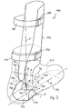
- shin guards 10 includes a Shin-shield 12, whose on a left lower leg fitting inside with a not separately shown in the figure shock-absorbing material is lined.
- the shield will go through lower tether 14 and an upper tether 16, the lower leg embrace, held, in such a way that the shield frictionally is fixable on the lower leg, so that in lower leg longitudinal direction the shield transmitted forces transmitted to the lower leg can be.
- At the non-positive fixing of the shield on Lower leg can also be the inner leg of the lower leg Protective shield participate.
- the surface to the shape of the Be adapted to the lower leg and can adhere to the inner surface be formed or have a high friction parameters.
- the tibia protector 10 has a foot below the two hocks embracing bracket member 22, the foot inside a subsequent to the shield 12 down Foot inside tension element 24, a to the foot inside tension element 24 subsequent, the foot engages under gripping element 26 and a fußau info mixedes, on the one hand foot outside on the shield 12 and on the other hand to the lower gripping element 26 subsequent fußau question mixedes Traction element 28 includes.
- the foot inside tension member 24 and the Foot outside tension members 28 each include a lower leg portion 30 and 32 and a lower leg portion 34 and 36, respectively.
- the foot inside upper leg portion 30 and the foot inside lower leg portion 34 are about a greatest effort to exercise.
- the tibial protective shield 12 if appropriate, not separate Shock absorbing inner lining, is in the illustrated embodiment formed integrally with the bracket member 22.
- the two joints 38 and 40 are each as material attenuation between upper Leg portion 30 and 32 and lower leg portion 34 and 36th trained, for example in the manner of a film hinge.
- plastic be used, taking for different sections of the unit Shield 12 and bracket member 22 plastic materials different Composition and properties can be used For example, softer and / or more elastic material for the tension elements 24 and 28 than for the shield 12. Also the tension elements even need not be formed of a single material.
- inner ankle 44 and the outer ankle 46 are upper Ankle joints shown as dashed circles. The location of approximately through both ankles going transverse axis of the upper ankle joint is connected by one the two ankles Connecting line H specified.
- connection line G connecting the two joints is G drawn by a point M 'about halfway between the two joints are going through vertical projection of a center M of the connecting line H halfway between the both ankles 44 and 46 results.
- the points M and M ' are thus on a vertically extending vertical axis V.
- a zur Vertical axis V and to a longitudinal axis L (foot longitudinal axis L or SchuhLhacksachse L) orthogonal and passing through the point M 'transverse axis (Foot transverse axis B or shoe transverse axis B) is also shown; the Axes L, V and B form a kind of orthogonal coordinate system for the shin guard 10 or for a combination of Shin guards 10 and associated shoe, at least when wearing of the shin guards or the combination.
- the extent of the displacement can be described by an angle ⁇ which are of a projection P of the connecting line G between both joints 38 and 40 on the transverse axis B containing horizontal plane E and the transverse axis B is included.
- the angle ⁇ is corresponding the intended limitation of the mobility of the foot relative to the lower leg to choose.
- the angle is preferably ⁇ at least 10 °, but preferably at least 20 °. Good results were in particular also at an angle of about 20 ° to 25 ° reached. For some purposes, the angle ⁇ should be at least 30 °.
- Joints 38 and 40 are opposite the ankles (circles 44 and 46) each offset downwards, about halfway up.
- the foot inside Joint 38 is deeper than the foot outside joint 40th Der Inclination angle of the connecting line G to the horizontal plane E is shown in FIG. 1 denoted by ⁇ . It is 5 ° to 15 °, preferably about 10 °.
- the forward and backward displacement of the joints 38 and 40 according to the Angle ⁇ leads to an increasing tensile load of the foot outside Tension element 28 with increasing supination or inversion movement. This is because in the course of the supination movement or Inversion movement of the foot increasingly around the Henkesche axis pivoted. This axis is opposite to the connecting line G between two joints 38 and 40 oriented, ie from behind laterally front medial. Accordingly, the joint 40 becomes increasingly tensile loaded and, provided the foot inside tension member as shown Embodiment is designed pressure-resistant, the foot inside Joint 38 increasingly loaded on pressure. The over the tension elements between fixed on the lower leg shield 12 and the Under gripping element 26 inhibit transmitted tensile and compressive forces increasingly the further supination movement or inversion movement.
- the particularly endangered ligament talofibolare anterius runs in front of the outer ankle (circle 46) as well as the foot outside Tension element 28, so that this hinge directly by the invention Tensile element protected against excessive tensile stress is.
- Figs. 2 to 4 are the same reference numerals for analog components or elements used, each increased by the number 100. It is only the Difference to the previously described embodiments explained and in this respect expressly to the preceding descriptions Referenced.
- Fig. 2 shows a tibial protector 110 according to the invention, which differs from Shinguards 10 of FIG. 1 only differs in that in the lower Area of the tibial protector 110, a textile garter 150 is provided is that on the inside of the shield 112 at this is fixed and is encompassed by the bracket member 122 on the outside.
- the entire bracket member 122, or at least the foot inside Tension element 124 and / or the foot outside tension element 128 can on Stocking 150 can be attached to relative positioning for proper positioning to provide the ankles 144 and 146.
- the sock part can also open be provided outside the bracket member.
- FIG. 3 is a shin guards shoe combination according to the invention 254 of a shin protector 210 according to the invention and a shoe 252 according to the invention, in particular sports shoe 252 shown.
- Sports shoe 252 is shown only schematically, with a sole 256 and a shaft 258.
- the insole 242 corresponds to the insoles 42 and 142 of the embodiments of FIGS. 1 and 2.
- the tibia protector 210 differs from the tibia protector 10 1 solely in that no lower gripping element is provided, but the lower leg portion 234 of the foot inside tension member 24 and the lower leg portion 236 of the foot outside Tension element 238 are shortened downwards and downwards respectively end in a free end.
- the two lower ones Leg portions 234 and 236 each as a fastening portion with a Velcro portion 260 and 262 formed on an associated Schmidtttabites on the outside of a foot inside shoe sidewall 264 or on the outside of a shoe outer side shoe sidewall 266 is attached.
- Fig. 3 takes over the shoe, or (More specifically) takes over a shoe section comprising a portion of foot inside shoe sidewall, a portion of the sole 256 and a portion of the foot outside shoe sidewall 266 between rechargeinnen workedem lower leg portion 234 and fußau finish workedem lower leg portion 236, the function of the in the embodiments 1 and 2 provided under gripping element 26 and 126, respectively.
- the said shoe portion can be used together with the foot inside Tension element 224 and the foot outside tension element 228 as a bracket element in the sense of the bracket member 22 and 122 of the embodiments be interpreted as shown in FIG. 1 and 2.
- FIG. 4 Another embodiment of a tibia saver according to the invention is shown in Fig. 4.
- Shinguard 310 is the stirrup element 322 of a too-elastic Band 370 is formed, which embraces the foot below the ankle and foot inside and foot outside to the shin protection shield 312 pulled up and connected to this.
- the elastic band 370 may be integrally formed with the shield 312 or as a separate Element attached to this.
- the various sections of the ductile tape 370 namely a Foot inside section 372, one between the sole of the foot and the shoe insole 32 arranged central portion 374 and a fußauniz partition 376 of the band 370 can be used as a foot-inside tension element 324, bottom gripping element 326 and foot outside tension element 328 identify.
- Reference numerals 324, 326 and 328 are in parentheses in addition to the reference numerals 372, 374 and 376 in Fig. 4 registered.
- the arrangement of the foot inside portion 272 and the foot outside Section 376 relative to the foot or relative to the ankles 344th and 346 corresponds to the arrangement of the foot inside tension member 24th and the foot outside tension member 28 according to that shown in FIG Embodiment.
- the foot inside section 372 is therefore (like the foot inside tension members 24, 124, 224) relative to the longitudinal direction A behind the foot inside ankle 344 arranged and the fußau finish dealte Section 376 is (like the foot outside tension members 28, 128, 228) relative to the longitudinal direction A in front of the foot outside ankle 346 arranged.
- the Relative movement of the foot relative to the lower leg by a deformation of the foot inside or foot outside band section over its entire length between middle section 379 and protective shield 312 be enabled.
- the entire foot inside or fußau jointe Band section 372 and 374 as the joint function supplying and thus as a "joint" in the sense of Definition of the invention to be identified effective joint zone are formed.
- the foot inside band portion 372 and the foot outside band portion But 374 can also as in the embodiment shown 4 be formed such that a well-defined foot inside effective joint zone 338 and a well-defined foot outer-side effective hinge zone 340 are formed as "joints" 338,340 in the sense of the definition of the invention to identify and a Pivoting movement of the foot or shoe relative to the tibia shield 12 characterized by the shin guard 310 is approved without significant counter-forces.
- the two effective ones Joint zones are shown in dashed lines in Fig. 4 and the connecting line G goes through the center of each effective joint zone.
- a Training well-localized effective joint zones or joints as in the embodiment Fig. 4 is not required because the restriction of the invention the movement of the foot relative to the lower leg alone Traction transmission between sole and lower leg by means of a foot inside or foot outside tension element can be achieved a particularly good protective function is achieved when the two tension elements not related to the longitudinal direction A on the same Height are arranged, but as in the described embodiments are offset from each other in the longitudinal direction A.
- the elastic band 370 (optionally also several, in particular in the longitudinal direction staggered Bands inside foot and / or foot outside) are other variants possible, which lead to further advantages. For example, that can Toughened band a progressively decreasing tensile elasticity when stretched and / or have a defined maximum extensibility.
- the formation of the tension elements in each case as zugelasticians band or as Band sections of an elastomeric band generally has the advantage that the supination movement (inversion movement) or pronation movement (Eversionsterrorism) limiting opposing forces not suddenly but that these forces gradually increase with increasing Build up the supination or pronation movement until one of the others Preventing supination or pronation movement or at least sufficiently slowing drag has been achieved. That's because of Extensibility of the traction elements inherently present joint play in the vertical direction and the gradual insertion of the Movement of the foot restricting counter-forces ensures a facilitated mobility of the foot and thus a particularly high Comfort.
- FIG. 4 is a variant of the shin guards 310th be explained.
- the variant is at the foot inside band section 372 and on the foot outer-side band section 376 each have an ankle cover protection shield 378 or 380 provided that the inner ankle 344 and the outer ankle 346 and from external action, For example, kicks when playing football, protects or such external At least damped effects.
- the ankle guards 378 and 380 can be made in one piece with the elastic band 370.
- To zugelastischen band 370 is still nachzutragen that this off Rubber or (preferably) consists of silicone rubber and a - related on a normal version of the shin guards 310 for an average big adult - a maximum elasticity of 3 cm based on the entire band and - based on the foot inside Band section 372 and the foot outside band section 376 - maximum 1.5 cm each.
- a Velcro portion 382 may be provided, with a corresponding Contrast Velcro section can be looped to the shoe insole.
- other ways of attaching the elastic band 370 to the shoe are conceivable. Accordingly, in the embodiments of FIG. 1 and 2, the lower gripping element and / or one or both tension elements (with the respective lower leg portion) on the shoe (in particular Insole or shoe sidewall) are attached.
Landscapes
- Health & Medical Sciences (AREA)
- General Health & Medical Sciences (AREA)
- Physical Education & Sports Medicine (AREA)
- Prostheses (AREA)
- Footwear And Its Accessory, Manufacturing Method And Apparatuses (AREA)
- Professional, Industrial, Or Sporting Protective Garments (AREA)
Claims (25)
- Protège-tibia (10 ; 110 ; 210 ; 310), en particulier protège-tibia de football, avec fonction de stabilisation de l'articulation du pied, prévu pour être porté en plus des chaussures afin de recouvrir au moins une zone inférieure de la jambe vers l'avant, comprenant :dans lequel les éléments de traction et l'élément de prise sous le pied sont appropriés pour transmettre au moins des forces de traction entre le pied du porteur et le plastron de protection et les éléments de traction (24, 28 ; 124, 128 ; 224, 228 ; 324, 328) sont appropriés pour permettre un mouvement de rotation du pied par rapport à la jambe du porteur ;un plastron de protection du tibia (12 ; 112 ; 212 ; 312) destiné à recouvrir au moins une zone inférieure de la jambe du porteur du protège-tibia vers l'avant, le plastron de protection (12 ; 112 ; 212 ; 312) présentant des moyens de retenue à l'aide desquels le plastron peut être positionné sur la jambe ;un élément de prise sous le pied (26 ; 126 ; 326) passant sous le pied du porteur,au moins un élément de traction du côté intérieur du pied (24 ; 124 ; 224 ; 324) et au moins un élément de traction du côté extérieur du pied (28 ; 128 ; 228 ; 328) qui sont reliés directement ou indirectement d'une part au plastron de protection et d'autre part à l'élément de prise sous le pied (26 ; 126 ; 326),
dans lequel les éléments de traction (24, 28 ; 124, 128 ; 224, 228 ; 324, 328) et l'élément de prise sous le pied (26 ; 126 ; 326) sont réalisés et disposés afin de limiter, par la transmission de force de traction et le cas échéant par la transmission de force de compression entre le plastron de protection (12 ; 112 ; 212 ; 312) pouvant être fixé par adhérence sur la jambe d'une part et le pied d'autre part, la mobilité du pied par rapport à la jambe au sens de limiter ou/et - au moins pour de grandes amplitudes de mouvement - au sens de ralentir/ rendre plus difficile au moins un type de mouvement susceptible de provoquer une blessure, en particulier l'inversion/supination ou/et l'éversion/pronation du pied,
caractérisé en ce que,
pour assurer cette protection contre les blessures, les éléments de traction (24, 28 ; 124, 128 ; 224, 228 ; 324, 328) ne permettent, au moins dans l'état porté du protège-tibia, entre l'élément de prise sous le pied (26 ; 126 ; 326) d'une part et le plastron de protection (12 ; 112 ; 212 ; 312) d'autre part qu'un mouvement de rotation qui est défini par une articulation du côté intérieur du pied (38 ; 138 ; 238 ; 338) qui est décalée vers l'arrière par rapport à la malléole interne (44 ; 144 ; 244 ; 344) et par une articulation du côté extérieur du pied (40 ; 140 ; 240 ; 340) qui est décalée vers l'avant par rapport à la malléole externe (46 ; 146 ; 246 ; 346) de telle façon qu'un axe de rotation caractérisant la mobilité permise en rotation s'étende en fonction de la position des articulations en s'écartant des axes de mouvement anatomiques qui caractérisent les mobilités relatives du pied et de la jambe. - Combinaison de protège-tibia et de chaussure avec une fonction de stabilisation de l'articulation du pied, avec un protège-tibia (10 ; 110 ; 210 ; 310), en particulier un protège-tibia de football, qui est prévu pour recouvrir au moins une zone inférieure de la jambe vers l'avant et une chaussure (252) associée, reliée ou à relier au protège-tibia et se terminant en dessous de la cheville du porteur, dans laquelle le protège-tibia comprend :dans laquelle les éléments de traction (24, 28 ; 124, 128 ; 224, 228 ; 324, 328) sont réalisés et disposés afin de limiter, par la transmission de force de traction et le cas échéant par la transmission de force de compression entre le plastron de protection (12 ; 112 ; 212 ; 312) pouvant être fixé par adhérence sur la jambe d'une part et sur la chaussure (252) d'autre part, la mobilité du pied par rapport à la jambe au sens de limiter ou/et - au moins pour de grandes amplitudes de mouvement - au sens de ralentir/rendre plus difficile au moins un type de mouvement susceptible de provoquer une blessure, en particulier l'inversion/supination ou/et l'éversion/pronation du pied,un plastron de protection du tibia (12 ; 112 ; 212 ; 312) destiné à recouvrir au moins une zone inférieure de la jambe du porteur du protège-tibia vers l'avant, le plastron de protection (12 ; 112 ; 212 ; 312) présentant des moyens de retenue à l'aide desquels le plastron peut être positionné sur la jambe ;au moins un élément de traction du côté intérieur du pied (24 ; 1 24 ; 224 ; 324) et au moins un élément de traction du côté extérieur du pied (28 ; 128 ; 228 ; 328) qui sont reliés directement ou indirectement d'une part au plastron de protection et qui sont reliés ou destinés à être reliés d'autre part à la chaussure en un point de liaison affecté, les éléments de traction et la chaussure étant appropriés pour transmettre au moins des forces de traction entre le pied du porteur et le plastron de protection et les éléments de traction (24, 28 ; 124, 128 ; 224, 228 ; 324, 328) étant appropriés pour permettre un mouvement de rotation du pied par rapport à la jambe du porteur ;
dans laquelle, pour assurer cette protection contre les blessures, les éléments de traction (24, 28 ; 124, 128 ; 224, 228 ; 324, 328) ne permettent, au moins dans l'état porté du protège-tibia, entre la chaussure (252) d'une part et le plastron de protection (12 ; 112 ; 212 ; 312) d'autre part qu'un mouvement de rotation qui est défini par une articulation du côté intérieur du pied (38 ; 138 ; 238 ; 338) qui est décalée vers l'arrière par rapport à la malléole interne (44 ; 144 ; 244 ; 344) et par une articulation du côté extérieur du pied (40 ; 140 ; 240 ; 340) qui est décalée vers l'avant par rapport à la malléole externe (46 ; 146 ; 246 ; 346) de telle façon qu'un axe de rotation caractérisant la mobilité permise en rotation s'étende en fonction de la position des articulations en s'écartant des axes de mouvement anatomiques qui caractérisent les mobilités relatives du pied et de la jambe. - Dispositif selon la revendication 1 ou la revendication 2, caractérisé en ce qu'un segment jambier (28 ; 128 ; 228 ; 328) de l'élément de traction du côté extérieur du pied (28 ; 128 ; 228 ; 328) est décalé vers l'avant par rapport à la malléole externe (46 ; 146 ; 246 ; 346) et en ce qu'un segment jambier (24 ; 124 ; 224 ; 324) de l'élément de traction du côté intérieur du pied (24 ; 124 ; 224 ; 324) est décalé vers l'arrière par rapport à la malléole interne (44 ; 144 ; 244 ; 344).
- Dispositif selon la revendication 1 ou la revendication 2, caractérisé en ce que l'articulation du côté extérieur du pied (40 ; 140 ; 240 ; 340) est décalée vers l'avant dans le sens longitudinal du pied par rapport à l'articulation du côté intérieur du pied (38 ; 138 ; 238 ; 338).
- Dispositif selon l'une des revendications précédentes, caractérisé en ce qu'un ou le segment jambier (28 ; 128 ; 228 ; 328) de l'élément de traction du côté extérieur du pied (28 ; 128 ; 228 ; 328) est décalé vers l'avant dans le sens longitudinal du pied par rapport à un ou au segment jambier (24 ; 124 ; 224 ; 324) de l'élément de traction du côté intérieur du pied (24; 124; 224; 324).
- Dispositif selon l'une des revendications précédentes, caractérisé en ce que l'articulation du côté extérieur du pied (40 ; 140 ; 240 ; 340) est décalée vers l'avant par rapport à une position médiane (M ou M') entre la malléole interne (44 ; 144 ; 244 ; 344) et la malléole externe (40 ; 140 ; 240 ; 340) ou/et en ce que l'articulation du côté intérieur du pied (38 ; 138 ; 238 ; 338) est décalée vers l'arrière par rapport à la position médiane (M ou M').
- Dispositif selon l'une des revendications précédentes, caractérisé en ce qu'un ou le segment jambier (28 ; 128 ; 228 ; 328) de l'élément de traction du côté extérieur du pied (28 ; 128 ; 228 ; 328) est décalé vers l'avant par rapport à une ou la position médiane (M ou M') entre la malléole interne (44 ; 144 ; 244 ; 344) et la malléole externe (46 ; 146 ; 246 ; 346) ou/et en ce qu'un ou le segment jambier (24 ; 124 ; 224 ; 324) de l'élément de traction du côté intérieur du pied (24 ; 124 ; 224 ; 324) est décalé vers l'arrière par rapport à la position médiane (M ou M').
- Dispositif selon l'une des revendications précédentes, caractérisé en ce qu'une droite de raccordement (G) passant d'une part par une articulation (38 ; 138 ; 238 ; 338) et d'autre part soit par un point médian (M) d'un segment de droite (H) reliant la malléole externe (46 ; 146 ; 246 ; 346) et la malléole interne, soit par l'autre articulation (40 ; 140 ; 240 ; 340) et un axe transversal du pied (B) projetés sur un plan horizontal (E) parallèle à l'axe transversal du pied (B) et à l'axe longitudinal du pied (A) font entre eux un angle d'au moins 10°, de préférence au moins 15°, de façon plus préférentielle au moins 20° et de la façon la plus préférentielle au moins 30°.
- Dispositif selon l'une des revendications précédentes, caractérisé en ce qu'une droite de raccordement (G) passant d'une part par une articulation (38 ; 138 ; 238 ; 338) et d'autre part soit par un point médian (M) d'un segment de droite (H) reliant la malléole externe (46 ; 146 ; 246 ; 346) et la malléole interne, soit par l'autre articulation (40 ; 140 ; 240 ; 340) et un axe transversal du pied (B) projetés sur un plan horizontal (E) parallèle à l'axe transversal du pied (B) et à l'axe longitudinal du pied (A) font entre eux un angle de 10° à 80°, de préférence de 20° à 45°.
- Dispositif selon l'une des revendications précédentes, caractérisé en ce qu'une droite de raccordement (G) passant d'une part par une articulation (38 ; 138 ; 238 ; 338) et d'autre part soit par un point médian (M) d'un segment de droite (H) reliant la malléole externe (46 ; 146 ; 246 ; 346) et la malléole interne, soit par l'autre articulation (40 ; 140 ; 240 ; 340) ou passant par un ou le segment jambier (28 ; 128 ; 228 ; 328) d'un élément de traction (28 ; 128 ; 228 ; 328) de l'autre côté du pied et un axe transversal du pied (B), projetés sur un plan horizontal (E) parallèle à l'axe transversal du pied (B) et à l'axe longitudinal du pied (A), font entre eux un angle d'au moins 10°, de préférence au moins 15°, de façon plus préférentielle au moins 20° et de la façon la plus préférentielle au moins 30 ° .
- Dispositif selon l'une des revendications précédentes, caractérisé en ce qu'une droite de raccordement (G) passant d'une part par une articulation (38 ; 138 ; 238 ; 338) et d'autre part soit par un point médian (M) d'un segment de droite (H) reliant la malléole externe (46 ; 146 ; 246 ; 346) et la malléole interne, soit par l'autre articulation (40 ; 140 ; 240 ; 340) ou passant par un ou le segment jambier (28 ; 128 ; 228 ; 328) d'un élément de traction (28 ; 128 ; 228 ; 328) de l'autre côté du pied et un axe transversal du pied (B), projetés sur un plan horizontal (E) parallèle à l'axe transversal du pied (B) et à l'axe longitudinal du pied (A), font entre eux un angle de 10° à 80°, de préférence de 20° à 45°.
- Dispositif selon l'une des revendications précédentes, caractérisé en ce que au moins un élément de traction (24, 28 ; 124, 128 ; 224, 228 ; 324, 328) comprend un segment d'élément de traction inférieur (34, 36 ; 134, 136 ; 234, 236 ; 334, 336) et un segment d'élément de traction supérieur (30, 32 ; 130, 132 ; 230, 232 ; 330, 332), en particulier un segment jambier inférieur (34, 36 ; 134, 136 ; 234, 236 ; 334, 336) et un segment jambier supérieur (30, 32 ; 130, 132 ; 230, 232 ; 330, 332), qui sont reliés par le biais de l'articulation du côté intérieur du pied (38 ; 138 ; 238 ; 338) ou par l'intermédiaire de l'articulation du côté extérieur du pied (40 ; 140 ; 240 ; 340).
- Dispositif selon la revendication 12, caractérisé en ce qu'au moins une articulation (338, 340) est réalisée avec un jeu d'articulation sensiblement vertical.
- Dispositif selon la revendication 12 ou la revendication 13, caractérisé en ce qu'au moins une articulation est réalisée sous la forme d'une combinaison de tourillon d'articulation et de logement, sous la forme d'un affaiblissement du matériau (38, 40 ; 138, 140 ; 238, 240), en particulier d'une articulation de type film, sous la forme d'un segment d'élément de traction (338, 340) fait d'un autre matériau par rapport au reste de l'élément de traction, en particulier d'un matériau plus mou ou/et plus élastique, ou sous la forme d'un segment à soufflet.
- Dispositif selon l'une des revendications précédentes, caractérisé en ce que l'un au moins des éléments de traction (324, 328) est réalisé au moins par zones sous forme élastique, en particulier sous la forme d'une bande élastique à la traction (370), le cas échéant avec une élasticité en traction variable dans le sens longitudinal de la bande ou/et avec une élasticité en traction qui diminue progressivement en fonction de l'allongement ou/et avec une extensibilité maximale définie.
- Dispositif selon la revendication 15, caractérisé en ce que la bande élastique à la traction (370) est faite de caoutchouc ou de caoutchouc silicone.
- Dispositif selon la revendication 15 ou la revendication 16, caractérisé en ce que l'extensibilité de l'élément de traction élastique à la traction (324, 328) dans le sens vertical est au maximum de 2,5 cm environ, de préférence au maximum de 2,0 cm environ et de la façon la plus préférentielle au maximum de 1,5 cm environ.
- Dispositif selon l'une des revendications précédentes, caractérisé en ce que les éléments de traction (24, 28 ; 124, 128 ; 224, 228 ; 324, 328) et le cas échéant l'élément de prise sous le pied (26 ; 126 ; 326) sont réalisés d'un seul tenant, en particulier d'une seule pièce, avec le plastron de protection (12 ; 112 ; 212 ; 312).
- Dispositif selon l'une des revendications précédentes, caractérisé par au moins un plastron de protection malléolaire (344, 346) qui est de préférence maintenu par un élément de traction du côté intérieur du pied (324) ou par un élément de traction du côté extérieur du pied (328) et qui est le cas échéant réalisé d'un seul tenant, en particulier d'une seule pièce, avec ledit élément de traction.
- Dispositif selon l'une des revendications précédentes, caractérisé en ce que les moyens de retenue comprennent au moins une bande de maintien (14, 16 ; 114, 116 ; 214, 216 ; 314, 316) à fixer autour de la jambe.
- Dispositif selon l'une des revendications précédentes, caractérisé en ce que les moyens de retenue comprennent deux bandes de maintien décalées l'une par rapport à l'autre dans le sens de la hauteur, élastiques à la traction et ajustables en largeur (14, 16 ; 114, 116 ; 214, 216 ; 314, 316), qui de préférence présentent chacune une fermeture (18, 20 ; 118, 120 ; 218, 220 ; 318 ; 320), le cas échéant une fermeture de type velcro.
- Dispositif selon l'une des revendications précédentes, caractérisé en ce qu'il est prévu une partie de manchette textile ou une partie de chaussette textile (150) enserrant la jambe, en particulier dans la zone de transition vers le pied, dans lequel la partie de manchette ou partie de chaussette (150) maintient de préférence le au moins un élément de traction (124, 128) dans une position prédéterminée par rapport au pied.
- Dispositif selon la revendication 22, caractérisé en ce qu'au moins un élément de traction et le cas échéant l'élément de prise sous le pied est réalisé d'un seul tenant ou d'une seule pièce avec la partie de chaussette ou de manchette.
- Combinaison de protège-tibia et de chaussure selon l'une des revendications 2 à 23 précédentes, caractérisée en ce que chaque élément de traction (224, 228) présente un segment d'extrémité inférieure libre (224, 236) qui est réalisé sous la forme d'un segment de fixation, en particulier un segment de type velcro (260, 262), pour une fixation résistant à la traction sur la chaussure (252).
- Combinaison de protège-tibia et de chaussure selon la revendication 24, caractérisée en ce que le segment de fixation forme une articulation ensemble avec un point de fixation affecté de la chaussure.
Priority Applications (3)
| Application Number | Priority Date | Filing Date | Title |
|---|---|---|---|
| AT97119249T ATE307645T1 (de) | 1997-11-04 | 1997-11-04 | Schienbeinschoner mit sprunggelenkstabilisierung |
| DE59712458T DE59712458D1 (de) | 1997-11-04 | 1997-11-04 | Schienbeinschoner mit Sprunggelenkstabilisierung |
| EP97119249A EP0920887B1 (fr) | 1997-11-04 | 1997-11-04 | Jambière avec stabilisation de la cheville |
Applications Claiming Priority (1)
| Application Number | Priority Date | Filing Date | Title |
|---|---|---|---|
| EP97119249A EP0920887B1 (fr) | 1997-11-04 | 1997-11-04 | Jambière avec stabilisation de la cheville |
Publications (2)
| Publication Number | Publication Date |
|---|---|
| EP0920887A1 EP0920887A1 (fr) | 1999-06-09 |
| EP0920887B1 true EP0920887B1 (fr) | 2005-10-26 |
Family
ID=8227570
Family Applications (1)
| Application Number | Title | Priority Date | Filing Date |
|---|---|---|---|
| EP97119249A Expired - Lifetime EP0920887B1 (fr) | 1997-11-04 | 1997-11-04 | Jambière avec stabilisation de la cheville |
Country Status (3)
| Country | Link |
|---|---|
| EP (1) | EP0920887B1 (fr) |
| AT (1) | ATE307645T1 (fr) |
| DE (1) | DE59712458D1 (fr) |
Families Citing this family (8)
| Publication number | Priority date | Publication date | Assignee | Title |
|---|---|---|---|---|
| DE60204883T3 (de) | 2002-09-05 | 2013-10-24 | Gambro Lundia Ab | Steuerung für eine Blutbehandlungsvorrichtung |
| ITTV20030133A1 (it) | 2003-09-26 | 2005-03-27 | Alpinestars Res Srl | Struttura di protezione degli arti inferiori del corpo umano. |
| EP2433662B1 (fr) | 2010-09-27 | 2014-06-04 | Gambro Lundia AB | Appareil pour le traitement extracorporel du sang |
| EP3799897B1 (fr) | 2011-08-30 | 2024-07-10 | Gambro Lundia AB | Appareil pour le traitement extracorporel du sang |
| PL2564884T3 (pl) | 2011-08-30 | 2014-11-28 | Gambro Lundia Ab | Urządzenie medyczne do pozaustrojowego oczyszczania płynu oraz sposób obliczania założonych natężeń przepływu w urządzeniu medycznym do podawania lub pobierania płynów |
| IT202000026206A1 (it) | 2020-11-03 | 2022-05-03 | Gambro Lundia Ab | Apparecchio per il trattamento extracorporeo del sangue e processo di calcolo delle portate impostate in un apparecchio medico per il trattamento extracorporeo del sangue. |
| IT202000026209A1 (it) | 2020-11-03 | 2022-05-03 | Gambro Lundia Ab | Apparatus for extracorporeal treatment of blood and process of calculating set flow rates in a medical apparatus for extracorporeal treatment of blood |
| IT202000026212A1 (it) | 2020-11-03 | 2022-05-03 | Gambro Lundia Ab | Apparecchio per il trattamento extracorporeo del sangue e processo di calcolo delle portate impostate in un apparecchio medico per il trattamento extracorporeo del sangue |
Family Cites Families (6)
| Publication number | Priority date | Publication date | Assignee | Title |
|---|---|---|---|---|
| AT361425B (de) * | 1978-09-06 | 1981-03-10 | Braun Peter | Beinschutz |
| US5301370A (en) * | 1992-01-23 | 1994-04-12 | Albion Hat & Cap Company Pty Limited | Shin pad with achilles tendon protection |
| DE4404911C2 (de) | 1994-02-16 | 1997-10-02 | Georg Dr Ahlbaeumer | Schuh, insbesondere Sportschuh oder orthopädischer Strumpf, mit Sprunggelenkstabilisierung |
| US5507720A (en) * | 1994-06-21 | 1996-04-16 | Lampropoulos; George | Shin and ankle protector |
| DE29601890U1 (de) | 1995-02-03 | 1997-06-19 | Ahlbäumer, Georg, Dr., Meggen | Schuh, insbesondere Sportschuh, mit Sprunggelenkstabilisierung |
| EP1416437A1 (fr) | 2002-11-04 | 2004-05-06 | STMicroelectronics S.r.l. | Porte quantique en hardware |
-
1997
- 1997-11-04 EP EP97119249A patent/EP0920887B1/fr not_active Expired - Lifetime
- 1997-11-04 AT AT97119249T patent/ATE307645T1/de not_active IP Right Cessation
- 1997-11-04 DE DE59712458T patent/DE59712458D1/de not_active Expired - Lifetime
Also Published As
| Publication number | Publication date |
|---|---|
| ATE307645T1 (de) | 2005-11-15 |
| DE59712458D1 (de) | 2005-12-01 |
| EP0920887A1 (fr) | 1999-06-09 |
Similar Documents
| Publication | Publication Date | Title |
|---|---|---|
| EP0744906B1 (fr) | Chaussure, notamment chaussure de sport ou bas orthopedique a stabilisation de la cheville | |
| EP1906890B1 (fr) | Bandage pour l'articulation de la cheville | |
| EP0627205B1 (fr) | Support pour la cheville | |
| DE3307815C1 (de) | Vorrichtung zur Anhebung des Vorderfusses waehrend des Gehens | |
| DE60005503T2 (de) | Sportschuh, insbesondere alpin-, touren-, oder langlaufskischuh | |
| DE69831010T2 (de) | Knöchel-fuss orthese | |
| EP3863460B1 (fr) | Dispositif d'amortissement du mouvement du pied et chaussure | |
| EP3621562B1 (fr) | Dispositif d'amortissement du mouvement du pied et chaussure destinée à amortir un mouvement du pied par le biais de la cheville | |
| DE19950509C1 (de) | Bandage zur Entlastung der Muskulatur beim Muskelfaserriß und ihre Verwendung | |
| DE2724586A1 (de) | Orthopaedische schiene zur stuetzung des kniegelenkes | |
| CH710341A1 (de) | Medizinischer Stabilschuh zur Sprunggelenkstabilisierung mit integriertem Stützsystem und regulierbarem Gelenk. | |
| EP0920887A1 (fr) | Jambière avec stabilisation de la cheville | |
| EP3661382B1 (fr) | Chaussure destinée à amortir un mouvement du pied par le biais de la cheville | |
| DE9100531U1 (de) | Fußorthese | |
| EP3854358A1 (fr) | Bandage d'articulation de genou | |
| DE102022116790B4 (de) | Vorrichtung zum Begrenzen und/oder Dämpfen einer Fußbewegung über das Sprunggelenk, und Schuh | |
| EP4574103B1 (fr) | Orthèse de cheville | |
| EP3854357B1 (fr) | Bandage pour articulation de genou | |
| DE202020100382U1 (de) | Kniegelenkbandage | |
| AT516229B1 (de) | Orthese | |
| DE102018006519A1 (de) | Vorrichtung zur Nachtlagerung und zur Unterstützung des Hebens eines Fußes gehbehinderter Patienten | |
| AT521027B1 (de) | Sicherheitsvorrichtung | |
| DE4100156A1 (de) | Volleyballschuh | |
| DE19733423B4 (de) | Fußstützeinrichtung mit einer Manschette | |
| DE9107480U1 (de) | Orthopädische Schiene zur Therapie des Spitzfußes |
Legal Events
| Date | Code | Title | Description |
|---|---|---|---|
| PUAI | Public reference made under article 153(3) epc to a published international application that has entered the european phase |
Free format text: ORIGINAL CODE: 0009012 |
|
| 17P | Request for examination filed |
Effective date: 19980706 |
|
| AK | Designated contracting states |
Kind code of ref document: A1 Designated state(s): AT BE CH DE ES FR GB IT LI NL PT SE |
|
| AX | Request for extension of the european patent |
Free format text: AL;LT;LV;RO;SI |
|
| AKX | Designation fees paid |
Free format text: AT BE CH DE ES FR GB IT LI NL PT SE |
|
| 17Q | First examination report despatched |
Effective date: 20020322 |
|
| GRAP | Despatch of communication of intention to grant a patent |
Free format text: ORIGINAL CODE: EPIDOSNIGR1 |
|
| GRAS | Grant fee paid |
Free format text: ORIGINAL CODE: EPIDOSNIGR3 |
|
| GRAA | (expected) grant |
Free format text: ORIGINAL CODE: 0009210 |
|
| AK | Designated contracting states |
Kind code of ref document: B1 Designated state(s): AT BE CH DE ES FR GB IT LI NL PT SE |
|
| PG25 | Lapsed in a contracting state [announced via postgrant information from national office to epo] |
Ref country code: NL Free format text: LAPSE BECAUSE OF FAILURE TO SUBMIT A TRANSLATION OF THE DESCRIPTION OR TO PAY THE FEE WITHIN THE PRESCRIBED TIME-LIMIT Effective date: 20051026 Ref country code: IT Free format text: LAPSE BECAUSE OF FAILURE TO SUBMIT A TRANSLATION OF THE DESCRIPTION OR TO PAY THE FEE WITHIN THE PRE;WARNING: LAPSES OF ITALIAN PATENTS WITH EFFECTIVE DATE BEFORE 2007 MAY HAVE OCCURRED AT ANY TIME BEFORE 2007. THE CORRECT EFFECTIVE DATE MAY BE DIFFERENT FROM THE ONE RECORDED.SCRIBED TIME-LIMIT Effective date: 20051026 Ref country code: GB Free format text: LAPSE BECAUSE OF FAILURE TO SUBMIT A TRANSLATION OF THE DESCRIPTION OR TO PAY THE FEE WITHIN THE PRESCRIBED TIME-LIMIT Effective date: 20051026 |
|
| REG | Reference to a national code |
Ref country code: GB Ref legal event code: FG4D Free format text: NOT ENGLISH |
|
| REG | Reference to a national code |
Ref country code: CH Ref legal event code: EP |
|
| PG25 | Lapsed in a contracting state [announced via postgrant information from national office to epo] |
Ref country code: AT Free format text: LAPSE BECAUSE OF NON-PAYMENT OF DUE FEES Effective date: 20051104 |
|
| PG25 | Lapsed in a contracting state [announced via postgrant information from national office to epo] |
Ref country code: BE Free format text: LAPSE BECAUSE OF NON-PAYMENT OF DUE FEES Effective date: 20051130 |
|
| REF | Corresponds to: |
Ref document number: 59712458 Country of ref document: DE Date of ref document: 20051201 Kind code of ref document: P |
|
| PG25 | Lapsed in a contracting state [announced via postgrant information from national office to epo] |
Ref country code: SE Free format text: LAPSE BECAUSE OF FAILURE TO SUBMIT A TRANSLATION OF THE DESCRIPTION OR TO PAY THE FEE WITHIN THE PRESCRIBED TIME-LIMIT Effective date: 20060126 |
|
| PG25 | Lapsed in a contracting state [announced via postgrant information from national office to epo] |
Ref country code: ES Free format text: LAPSE BECAUSE OF FAILURE TO SUBMIT A TRANSLATION OF THE DESCRIPTION OR TO PAY THE FEE WITHIN THE PRESCRIBED TIME-LIMIT Effective date: 20060206 |
|
| PG25 | Lapsed in a contracting state [announced via postgrant information from national office to epo] |
Ref country code: PT Free format text: LAPSE BECAUSE OF FAILURE TO SUBMIT A TRANSLATION OF THE DESCRIPTION OR TO PAY THE FEE WITHIN THE PRESCRIBED TIME-LIMIT Effective date: 20060327 |
|
| NLV1 | Nl: lapsed or annulled due to failure to fulfill the requirements of art. 29p and 29m of the patents act | ||
| GBV | Gb: ep patent (uk) treated as always having been void in accordance with gb section 77(7)/1977 [no translation filed] |
Effective date: 20051026 |
|
| PLBE | No opposition filed within time limit |
Free format text: ORIGINAL CODE: 0009261 |
|
| STAA | Information on the status of an ep patent application or granted ep patent |
Free format text: STATUS: NO OPPOSITION FILED WITHIN TIME LIMIT |
|
| 26N | No opposition filed |
Effective date: 20060727 |
|
| EN | Fr: translation not filed | ||
| PG25 | Lapsed in a contracting state [announced via postgrant information from national office to epo] |
Ref country code: FR Free format text: LAPSE BECAUSE OF FAILURE TO SUBMIT A TRANSLATION OF THE DESCRIPTION OR TO PAY THE FEE WITHIN THE PRESCRIBED TIME-LIMIT Effective date: 20061215 |
|
| BERE | Be: lapsed |
Owner name: AHLBAUMER, GEORG Effective date: 20051130 |
|
| PGFP | Annual fee paid to national office [announced via postgrant information from national office to epo] |
Ref country code: CH Payment date: 20080229 Year of fee payment: 11 |
|
| PG25 | Lapsed in a contracting state [announced via postgrant information from national office to epo] |
Ref country code: FR Free format text: LAPSE BECAUSE OF FAILURE TO SUBMIT A TRANSLATION OF THE DESCRIPTION OR TO PAY THE FEE WITHIN THE PRESCRIBED TIME-LIMIT Effective date: 20051130 |
|
| PG25 | Lapsed in a contracting state [announced via postgrant information from national office to epo] |
Ref country code: FR Free format text: LAPSE BECAUSE OF FAILURE TO SUBMIT A TRANSLATION OF THE DESCRIPTION OR TO PAY THE FEE WITHIN THE PRESCRIBED TIME-LIMIT Effective date: 20051026 |
|
| REG | Reference to a national code |
Ref country code: CH Ref legal event code: PL |
|
| PG25 | Lapsed in a contracting state [announced via postgrant information from national office to epo] |
Ref country code: LI Free format text: LAPSE BECAUSE OF NON-PAYMENT OF DUE FEES Effective date: 20081130 Ref country code: CH Free format text: LAPSE BECAUSE OF NON-PAYMENT OF DUE FEES Effective date: 20081130 |
|
| PGFP | Annual fee paid to national office [announced via postgrant information from national office to epo] |
Ref country code: DE Payment date: 20090814 Year of fee payment: 13 |
|
| REG | Reference to a national code |
Ref country code: DE Ref legal event code: R119 Ref document number: 59712458 Country of ref document: DE Effective date: 20110601 Ref country code: DE Ref legal event code: R119 Ref document number: 59712458 Country of ref document: DE Effective date: 20110531 |
|
| PG25 | Lapsed in a contracting state [announced via postgrant information from national office to epo] |
Ref country code: DE Free format text: LAPSE BECAUSE OF NON-PAYMENT OF DUE FEES Effective date: 20110531 |