EP0920889A1 - Willkürlich schliess- und lösbare Verbindungseinrichtung - Google Patents
Willkürlich schliess- und lösbare Verbindungseinrichtung Download PDFInfo
- Publication number
- EP0920889A1 EP0920889A1 EP98122588A EP98122588A EP0920889A1 EP 0920889 A1 EP0920889 A1 EP 0920889A1 EP 98122588 A EP98122588 A EP 98122588A EP 98122588 A EP98122588 A EP 98122588A EP 0920889 A1 EP0920889 A1 EP 0920889A1
- Authority
- EP
- European Patent Office
- Prior art keywords
- base plate
- shoe
- connecting device
- driver
- locking
- Prior art date
- Legal status (The legal status is an assumption and is not a legal conclusion. Google has not performed a legal analysis and makes no representation as to the accuracy of the status listed.)
- Granted
Links
- 230000002747 voluntary effect Effects 0.000 title 1
- 230000005540 biological transmission Effects 0.000 claims abstract description 15
- 238000010276 construction Methods 0.000 description 6
- 230000000903 blocking effect Effects 0.000 description 2
- 238000013459 approach Methods 0.000 description 1
- 235000013405 beer Nutrition 0.000 description 1
- 239000000969 carrier Substances 0.000 description 1
- 238000005516 engineering process Methods 0.000 description 1
- 238000003780 insertion Methods 0.000 description 1
- 230000037431 insertion Effects 0.000 description 1
- 239000000463 material Substances 0.000 description 1
- 239000007787 solid Substances 0.000 description 1
Images


Classifications
-
- A—HUMAN NECESSITIES
- A63—SPORTS; GAMES; AMUSEMENTS
- A63C—SKATES; SKIS; ROLLER SKATES; DESIGN OR LAYOUT OF COURTS, RINKS OR THE LIKE
- A63C10/00—Snowboard bindings
- A63C10/02—Snowboard bindings characterised by details of the shoe holders
- A63C10/10—Snowboard bindings characterised by details of the shoe holders using parts which are fixed on the shoe, e.g. means to facilitate step-in
- A63C10/103—Snowboard bindings characterised by details of the shoe holders using parts which are fixed on the shoe, e.g. means to facilitate step-in on the sides of the shoe
-
- A—HUMAN NECESSITIES
- A63—SPORTS; GAMES; AMUSEMENTS
- A63C—SKATES; SKIS; ROLLER SKATES; DESIGN OR LAYOUT OF COURTS, RINKS OR THE LIKE
- A63C10/00—Snowboard bindings
- A63C10/16—Systems for adjusting the direction or position of the bindings
- A63C10/18—Systems for adjusting the direction or position of the bindings about a vertical rotation axis relative to the board
-
- Y—GENERAL TAGGING OF NEW TECHNOLOGICAL DEVELOPMENTS; GENERAL TAGGING OF CROSS-SECTIONAL TECHNOLOGIES SPANNING OVER SEVERAL SECTIONS OF THE IPC; TECHNICAL SUBJECTS COVERED BY FORMER USPC CROSS-REFERENCE ART COLLECTIONS [XRACs] AND DIGESTS
- Y10—TECHNICAL SUBJECTS COVERED BY FORMER USPC
- Y10T—TECHNICAL SUBJECTS COVERED BY FORMER US CLASSIFICATION
- Y10T403/00—Joints and connections
- Y10T403/59—Manually releaseable latch type
- Y10T403/591—Manually releaseable latch type having operating mechanism
-
- Y—GENERAL TAGGING OF NEW TECHNOLOGICAL DEVELOPMENTS; GENERAL TAGGING OF CROSS-SECTIONAL TECHNOLOGIES SPANNING OVER SEVERAL SECTIONS OF THE IPC; TECHNICAL SUBJECTS COVERED BY FORMER USPC CROSS-REFERENCE ART COLLECTIONS [XRACs] AND DIGESTS
- Y10—TECHNICAL SUBJECTS COVERED BY FORMER USPC
- Y10T—TECHNICAL SUBJECTS COVERED BY FORMER US CLASSIFICATION
- Y10T403/00—Joints and connections
- Y10T403/70—Interfitted members
- Y10T403/7009—Rotary binding cam or wedge
Definitions
- the invention relates to an arbitrarily closable and releasable Connection device for connecting a sports shoe and a sports device, preferably a snowboard, with one to be firmly mounted on it Base plate on which the sole of the shoe can be supported and locked, for which purpose lateral recesses is provided for receiving locking elements Facility, two of which relate to a central pivot point for the shoe diametrically opposite are rigidly provided on the base plate.
- the connecting devices proposed here have at least two Holding elements for the shoe, which engage on the long sides of the shoe sole, and at least one fastener that can be actuated against spring force, the one Actuating part against which the shoe against when inserted into the device acts the spring force and thereby the fastener from an open position in brings a stop.
- connection devices for connecting a Snowboard boots and a snowboard are said to be the aforementioned Connection devices in terms of their longitudinal extension short can be strong, so that even with extremely narrow snowboards cut turns can be performed. There is also a manual closing the connecting device avoided after inserting a shoe.
- connection devices with "step in” options
- the connecting device in which the shoe is placed at an angle to the position of use on the base plate and through subsequent pivoting about a vertical axis brought into its holding position can be.
- This construction has, as well known, with only two side Locking elements that prevent the shoe from lifting and moving secure on the base plate, the disadvantage of an inadequate connection of the board and shoes that do not allow exact board guidance, especially not in extreme situations and in steep terrain, which unsettles the user and also at risk.
- step in principle for closing the connection device has compared to the "Twist in” principle has the major disadvantage that the device before insertion a shoe must be largely free of snow and ice so that the necessary Locking can take place.
- the invention aims, starting from the known twist described above in-bond to create a connection device that the shoe in the Use position provides an optimal grip on the sports equipment, so that this from User is well controllable and precisely controllable in all situations.
- the base plate as a housing for the transmission.
- the gear can one around have central pivot point swiveling ring gear, which the two movable Locking elements carries.
- the axis of a gear wheel can then be used as a carrier serve, whose teeth on the one hand with those of the ring gear and on the other hand with a Comb the internal teeth fixed to the base plate.
- the axis of the gear wheel expediently tapers at its free end.
- it is intended for direct engagement in a hole in the shoe sole.
- This hole can merge into one on its semicircle facing the ski tip pass over a widening recess in the sole of the shoe, so that a slight Positioning the shoe when placing it on the base plate is possible.
- the connecting device instead of a ring gear in the gearbox a rotatable around the central pivot point Disc in front of which the driver is provided.
- the driver in operative connection with an arm of a two-armed lever, which in the base plate is pivotally mounted about a vertical axis. It is at the free ends of the two lever arms each with a plunger, and for the plunger sliding guides are provided in the base plate. Form the free ends of the plungers or carry the further locking elements according to the invention.
- Another embodiment provides that the other locking elements as Quarter-turn lock designed, mounted on vertical axes in the base plate and in Opening direction are loaded by a spring that the rotary latch on the outside Bear control cam, which is acted upon by a roller, and that these rollers on axles arranged parallel to the driver on the turntable are.
- two drivers are expediently provided, in such a way that both in the closed position of the device in the vertical Longitudinal median plane of the facility. This is not just a danger possible jamming of a link of the gearbox but also eliminates one better possibility of operation given by the shoe, which in the case of Using pins directly as drivers then also a second hole in the Has shoe sole.
- Yet another construction of the connecting device according to the invention provides two drivers. That each driver is in operative connection with one Slider stands that the slider is identical and in sliding guides Base plate are stored and that the free ends of the slide the other Form or wear locking elements.
- a locking member for blocking the gear of the closed position can be in the Base plate provided vertically displaceable locking pin loaded by a spring and with its inner end in a locking recess of the ring gear or the Disk of the gear unit can be snapped into place. At its outer end is the locking pin as Actuator handle or designed to connect such.
- a spring-loaded as a locking member for the transmission Pawl on the base plate serves that on the ring gear or the disc of Gear a locking tooth is provided and that the pawl a Actuating handle or the connection for such.
- Another construction provides that as a locking member for the transmission between the Base plate and the ring gear or the disk a beer bottle cap-like Double lever is provided.
- the connecting devices shown serve to connect one Snowboard shoe with a snowboard.
- the snowboard shoe or its sole is indicated by dash-dotted lines in most of the figures, while a representation of the Snowboards has been dispensed with.
- the respective base plate in its central area four curved around the center Elongated holes 1, which are known for receiving fastening screws to serve.
- the snowboard boots used have a solid sole with recesses, as is already known.
- the connecting device for each side of the Shoe sole has two locking elements that are diametrically opposed to each other in pairs opposite.
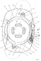
- a base plate 2 is present, which in in the central area of its two long sides each carries a wall 3 or 4.
- the Inside of the walls are designed and spaced apart so that the shoe can be used with its sole between them and swiveled to a sufficient extent.
- An annular groove 5 of the base plate is expanded at the front and rear at 6 and 7 respectively Provided on the inside in this area with an internal toothing 8.
- Gears are two gears 9 in the manner of planet gears in engagement, the on the other hand are engaged with teeth 10 which are provided on a ring gear 11 are, which is mounted in the annular groove 5 of the base plate.
- the gears 9 are on their Axes 12 in elongated holes 13 curved around the central pivot point Base plate 2 stored.
- the axes 12 of the gears extend from the Base plate 2 up and taper at its free ends. With these The free ends form the drivers, which are in corresponding holes in the axis Shoe sole can intervene and as a drive member of the transmission for closing or Solve the connection device. In the closed position of the Connection device, the two drivers are in the vertical Longitudinal median plane (see Figure 2).
- a locking element is used to secure the closed position of the connecting device present, which is formed by the lower end 14 of a pin 15 which in a vertical recess 16 is provided in the wall 4 of the base plate 2 and with protrudes from the wall at its upper end.
- a spring 17 the pin is after burdened below, so that in the locked position an unintended solution of the Connection device is not possible.
- One for engaging the lower end 14 of the Pin serving hole 18 in the ring gear 11 can be seen in Figure 1.
- the ring gear 11 carries two locking elements 19, 20. These elements are integrally formed with the ring gear and a double through the end Turn 21 or 22 reached. The turns extend through slots 23, 24 in the base plate 2, which are in sufficiently large recesses 25, 26 in the Walls 3 and 4 open (see in particular Fig. 4). Finally everyone carries Side wall 3 and 4 a locking element 27 and 28, respectively Locking elements that are immovably mounted in the walls are in With respect to the central pivot point for the shoe diametrically opposite each other.
- Figure 1 shows the connecting device in the entry and exit position. In this Position, the shoe can easily be lifted off the base plate.
- the connecting device allows the shoe to be shown in dash-dotted lines Lower the layer onto the base plate.
- at least the front hole is widened towards the toe, so that when inserting the shoe automatically with a forward movement its positioning results.
- the shoe sole has two recesses on each side for receiving the Locking elements.
- each side wall there is another one Locking element formed in each side wall as a rotary latch 45 and 46, respectively are pivotable about an axis 47 or 48 in the respective side wall.
- the outer The end face of each rotary bolt is designed as a cam, on each of which a roller 49 or 50 can expire.
- the disk 38 is provided with two further lugs 51, which, as can be seen from FIG. 8, are angled in a Z-shape and each by means of a Axle journal 52 carry a roller 49 or 50.
- the locking bolts are not loaded by springs in the opening direction. That's what they're for The rotary latch is designed as an angle lever, the short lever arm of which has an opening nose 53 or 54 forms. The control curve extends to the end of the nose.
- the locking device to prevent rotation of the disc 38 and thus to determine the Gearbox in the closed position of the connecting device corresponds that of the embodiment described with reference to Figures 1 to 5, to the hereby is referred.
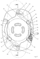
- a third embodiment of a connecting device show the figures 9 to 12.
- the base plate designated 57 in turn carries lateral walls 58, 59.
- an annular groove 60 is provided, which as in the previous versions a front extension 61 and a rear Extension 62 has.
- in the base plate again elongated holes 63 around a central pivot point through which pins 64, which serve as drivers, extend.
- This Carriers are located on lugs 65, 66 of an annular disc 67 which in the Ring groove 60 of the base plate is mounted. Above the disc are in the base plate Two slide guides 68, 69 are provided for receiving one of two identical slides 70.
- slides 70 are at their inner ends angled and have in this bend an elongated hole 71, the width corresponds to the diameter of the pins 64 and that of one of the pins is enforced (see in particular Figure 11).
- the outer end of the flat material formed slide is angled and back again (see in particular Figure 12). With these parts angled back and labeled 72, they form the two Slider each have a locking element.
- the slide guides 68, 69 each open in the base plate in a corresponding manner large recess 73 in the side walls 58, 59.
- the wall 59 is partially cut away for better Representation of a locking member, which is designed as a pawl 76 and around a Axle journal 77 is pivotable.
- the pawl is in the plane of the disc 67.
- a locking tooth 78 is formed by a recess on the circumference of the disk, which is engaged by the pawl in the closed position of the device (see FIG 10).
- the pawl is approximately T-shaped.
- the arm in the extension of the latch arm is loaded by a spring 79, while the web as Actuation handle serves.
- FIG. 9 again shows the connecting device in the entry and exit position.
- the device is moved into the position according to FIG. 10 by pivoting the shoe transferred.
- the pawl 76 secures by reaching behind the locking tooth 78, the position of the disc 67 and thus also the blocking of the Shoe by means of the locking elements.
- the shoe can then be returned to the position shown in FIG. 9 rotate.
- the base plate is designed as a housing for the transmission.
Landscapes
- Footwear And Its Accessory, Manufacturing Method And Apparatuses (AREA)
- Hooks, Suction Cups, And Attachment By Adhesive Means (AREA)
Abstract
Description
- Figur 1:
- die Draufsicht auf die Verbindungseinrichtung im geöffneten Zustand,
- Figur 2:
- die Draufsicht entsprechend Figur 1, jedoch im geschlossenen Zustand der Verbindungseinrichtung,
- Figur 3:
- einen Längsschnitt durch die Verbindungseinrichtung nach der Linie A-A in Figur 2,
- Figur 4:
- einen Querschnitt durch die Verbindungseinrichtung nach der Linie B-B in Figur 2,
- Figur 5:
- einen Teilschnitt nach der Linie C-C in Figur 1,
- Figur 6:
- die Draufsicht auf eine zweite Ausführung der Verbindungseinrichtung, wiederum im geöffneten Zustand,
- Figur 7:
- eine Draufsicht entsprechend Figur 6, jedoch im geschlossenen Zustand der Verbindungseinrichtung,
- Figur 8:
- einen Querschnitt durch die Verbindungseinrichtung nach der Linie D-D in Figur 7,
- Figur 9:
- die Draufsicht einer dritten Ausführung der Verbindungseinrichtung im geöffneten Zustand,
- Figur 10:
- eine Draufsicht entsprechend Figur 9, jedoch im geschlossenen Zustand der Verbindungseinrichtung,
- Figur 11:
- einen Längsschnitt durch die Verbindungseinrichtung nach der Linie E-E in Figur 10 und
- Figur 12:
- eine Seitenansicht der Verbindungseinrichtung in Pfeilrichtung F in Figur 9.
Claims (11)
- Willkürlich schließ- und lösbare Verbindungseinrichtung zum Verbinden eines Sportschuhes und eines Sportgerätes, vorzugsweise eines Snowboards, mit einer auf diesem fest zu montierenden Grundplatte, auf der die Schuhsohle abstützbar und verriegelbar ist, wozu diese mit seitlichen Aussparungen versehen ist zur Aufnahme von Verriegelungselementen der Einrichtung, von denen zwei in Bezug auf einen zentralen Drehpunkt für den Schuh einander diametral gegenüberliegend starr an der Grundplatte vorgesehen sind,
dadurch gekennzeichnet, daß die Einrichtung für jede Seite der Schuhsohle ein weiteres Verriegelungselement (19, 20; 45, 46, 72) besitzt, daß diese weiteren Verriegelungselemente sich ebenfalls einander diametral gegenüberliegen und über ein Getriebe (8, 9, 11; 38, 41, 45, 49; 67, 70) mit der Grundplatte (2, 32, 57) verbunden sind, daß als Antriebsglied des Getriebes mindestens ein gegenüber der Abstützfläche der Grundplatte vorstehender, vom Schuh betätigbarer Mitnehmer (12, 41, 64) vorgesehen ist, der in einem um den zentralen Drehpunkt gekrümmten Langloch (13, 42, 63) in der Grundplatte geführt ist, und daß die Grundplatte für das Getriebe ein Sperrglied (15, 76) aufweist, welches das Getriebe in der Schließlage blockiert. - Verbinbindungseinrichtung nach Anspruch 1 dadurch gekennzeichnet, daß das Getriebe einen um den zentralen Drehpunkt schwenkbaren Zahnkranz (11) besitzt, der die beiden beweglichen Verriegelungselement (19, 20) trägt.
- Verbindungseinrichtung nach einem der vorhergehenden Ansprüche, dadurch gekennzeichnet, daß als Mitnehmer die Achse (12) eines Zahnrades (9) dessen Zähne einerseits mit denen des Zahnkranzes und andererseits mit einer grundplattenfesten Innenverzahnung (8) kämmen.
- Verbindungseinrichtung nach Anspruch 3, dadurch gekennzeichnet, daß die Achse des Zahnrades einen U-förmigen Trittbügel trägt, dessen Schenkelabstand der Sohlenbreite entspricht.
- Verbindungseinrichtung nach Anspruch 1 dadurch gekennzeichnet, daß das Getriebe eine um den zentralen Drehpunkt drehbare Scheibe (38) aufweist, an der der Mitnehmer (41) vorgesehen ist.
- Verbindungseinrichtung nach Anspruch 5 , dadurch gekennzeichnet, daß der Mitnehmer in Wirkverbindung mit einem Arm eines zweiarmigen Hebels steht, der in der Grundplatte um eine vertikale Achse schwenkbar gelagert ist, daß an den freien Enden der beiden Hebelarme jeweils ein Stößel angelenkt ist, für die in der Grundplatte Gleitführungen vorgesehen sind, und daß die freien Enden der Stößel die weiteren Verriegelungselemente bilden oder tragen.
- Verbindungseinrichtung nach Anspruch 5, dadurch gekennzeichnet, daß die weiteren Veriegelungselemente als Drehriegel (45, 46) ausgebildet, um vertikale Achsen (47, 48) in der Grundplatte (32) gelagert und in Öffnungsrichtung von einer Feder belastet sind, daß die Drehriegel außenseitig eine Steuerkurve tragen, die von einer Rolle (49, 50) beaufschlagt ist, und daß diese Rollen auf parallel zu dem Mitnehmer (41) an der drehbaren Scheibe (38) angeordneten Achsen (52) gelagert sind.
- Verbindungseinrichtung nach Anspruch 7, dadurch gekennzeichnet, daß der Drehriegel (45, 46) anstelle der Feder oder zusätzlich mit einer Öffnungsnase (53, 54) versehen ist und daß die Steuerkurve sich bis zum Ende der Nase erstreckt.
- Verbindungseinrichtung nach einem der vorhergehenden Ansprüche, dadurch gekennzeichnet daß zwei Mitnehmer (12 , 41, 64) vorgesehen sind und daß beide Mitnehmer in der Schließlage der Einrichtung in der vertikalen Längsmittelebene liegen.
- Verbindungseinrichtung nach den Ansprüchen 5 und 9 dadurch gekennzeichnet, daß jeder Mitnehmer (64) in Wirkverbindung mit einem Schieber (70) steht, daß die Schieber identisch ausgebildet und in Gleitführungen der Grundplatte (57) gelagert sind und daß die freien Enden der Schieber (70) die weiteren Verriegelungselemente (72) bilden oder tragen.
- Verbindungseinrichtung nach Anspruch 2 oder 5 dadurch gekennzeichnet, daß als Sperrglied für das Getriebe ein in der Grundplatte (2, 32 ) vertikal verschiebbarer, von einer Feder (17) belasteter Sperrstift (15) vorgesehen und mit seinem inneren Ende in eine Rastausnehmung (18) des Zahnkranzes (11) bzw. der Scheibe (38) des Getriebes einrastbar ist und daß der Sperrstift (15 ) an seinem äußeren Ende als Betätigungshandhabe oder zum Anschluß einer solchen ausgebildet ist.
Applications Claiming Priority (2)
| Application Number | Priority Date | Filing Date | Title |
|---|---|---|---|
| DE19754041A DE19754041A1 (de) | 1997-12-05 | 1997-12-05 | Willkürlich schließ- und lösbare Verbindungseinrichtung |
| DE19754041 | 1997-12-05 |
Publications (2)
| Publication Number | Publication Date |
|---|---|
| EP0920889A1 true EP0920889A1 (de) | 1999-06-09 |
| EP0920889B1 EP0920889B1 (de) | 2003-03-19 |
Family
ID=7850889
Family Applications (1)
| Application Number | Title | Priority Date | Filing Date |
|---|---|---|---|
| EP98122588A Expired - Lifetime EP0920889B1 (de) | 1997-12-05 | 1998-12-03 | Willkürlich schliess- und lösbare Verbindungseinrichtung |
Country Status (5)
| Country | Link |
|---|---|
| US (1) | US6290423B1 (de) |
| EP (1) | EP0920889B1 (de) |
| JP (1) | JP4228156B2 (de) |
| AT (1) | ATE234651T1 (de) |
| DE (2) | DE19754041A1 (de) |
Cited By (1)
| Publication number | Priority date | Publication date | Assignee | Title |
|---|---|---|---|---|
| US6631919B1 (en) | 2000-01-06 | 2003-10-14 | The Burton Corporation | Wing-shaped leg support for a highback |
Families Citing this family (8)
| Publication number | Priority date | Publication date | Assignee | Title |
|---|---|---|---|---|
| US20030090072A1 (en) * | 1998-02-17 | 2003-05-15 | Cole Charles D. | Freely rotatable binding for snowboarding and other single-board sports |
| FR2801512B1 (fr) * | 1999-11-30 | 2001-12-21 | Rossignol Sa | Plaque interface montee sur une planche de surf |
| US7329065B2 (en) * | 2004-11-05 | 2008-02-12 | Spx Corporation | Coupling assembly and method for connecting and disconnecting a shaft assembly |
| DE102006006574B4 (de) * | 2006-02-13 | 2008-11-27 | Beck, Tilmann, Dr.Dr. | Bindungseinheit |
| US7571924B2 (en) * | 2006-06-14 | 2009-08-11 | Rick White | Rotatable snowboard boot binding apparatus |
| US8979097B2 (en) | 2013-03-14 | 2015-03-17 | Charles D. Cole, III | Rotatable footplate integrated with a bearing assembly imbedded in a single-board sport board |
| US9272760B2 (en) * | 2014-07-31 | 2016-03-01 | John D. Bruce | Adjustable boot for a water sport device |
| US10105586B1 (en) * | 2017-07-19 | 2018-10-23 | Tristan Olsen-Lund | Mounting system for snowboard bindings and snowboard binding including same |
Citations (4)
| Publication number | Priority date | Publication date | Assignee | Title |
|---|---|---|---|---|
| FR2725140A1 (fr) * | 1994-10-03 | 1996-04-05 | Guittard Christian | Dispositif d'orientation des fixations de planche des neiges |
| ITTV960108A1 (it) * | 1996-09-04 | 1996-12-04 | Adriano Girotto | Attacco per snowboard con bloccaggio tramite rotazione |
| EP0788819A2 (de) * | 1995-01-20 | 1997-08-13 | The Burton Corporation | Skischuhbindungssystem für Snowboards |
| DE19611111A1 (de) * | 1996-03-21 | 1997-09-25 | Franz Hegele | Bindung für Snowboards |
Family Cites Families (7)
| Publication number | Priority date | Publication date | Assignee | Title |
|---|---|---|---|---|
| CH676205A5 (de) * | 1989-05-04 | 1990-12-28 | Urs P Meyer | |
| US5971420A (en) * | 1994-06-06 | 1999-10-26 | Shimano, Inc. | Snowboard binding |
| US5586779A (en) * | 1995-06-06 | 1996-12-24 | Dawes; Paul J. | Adjustable snowboard boot binding apparatus |
| DE69712506T2 (de) * | 1996-06-25 | 2002-11-14 | Brant W Berger | Snowboardbindung |
| IT1288636B1 (it) * | 1996-07-05 | 1998-09-23 | Nordica Spa | Dispositivo di regolazione angolare particolarmente per un attacco da snowboard |
| US5906388A (en) * | 1997-01-14 | 1999-05-25 | Quiksilver, Inc. | Footwear mounting system |
| KR100211747B1 (ko) * | 1997-07-15 | 1999-08-02 | 이종구 | 스노우보드 바인더 |
-
1997
- 1997-12-05 DE DE19754041A patent/DE19754041A1/de not_active Withdrawn
-
1998
- 1998-11-23 US US09/197,635 patent/US6290423B1/en not_active Expired - Lifetime
- 1998-12-03 AT AT98122588T patent/ATE234651T1/de active
- 1998-12-03 EP EP98122588A patent/EP0920889B1/de not_active Expired - Lifetime
- 1998-12-03 DE DE59807535T patent/DE59807535D1/de not_active Expired - Lifetime
- 1998-12-07 JP JP34691698A patent/JP4228156B2/ja not_active Expired - Fee Related
Patent Citations (5)
| Publication number | Priority date | Publication date | Assignee | Title |
|---|---|---|---|---|
| FR2725140A1 (fr) * | 1994-10-03 | 1996-04-05 | Guittard Christian | Dispositif d'orientation des fixations de planche des neiges |
| EP0788819A2 (de) * | 1995-01-20 | 1997-08-13 | The Burton Corporation | Skischuhbindungssystem für Snowboards |
| DE19611111A1 (de) * | 1996-03-21 | 1997-09-25 | Franz Hegele | Bindung für Snowboards |
| ITTV960108A1 (it) * | 1996-09-04 | 1996-12-04 | Adriano Girotto | Attacco per snowboard con bloccaggio tramite rotazione |
| WO1998009690A1 (en) * | 1996-09-04 | 1998-03-12 | Buckfield Contracting Limited | Locking device particularly for snowboards |
Cited By (1)
| Publication number | Priority date | Publication date | Assignee | Title |
|---|---|---|---|---|
| US6631919B1 (en) | 2000-01-06 | 2003-10-14 | The Burton Corporation | Wing-shaped leg support for a highback |
Also Published As
| Publication number | Publication date |
|---|---|
| DE59807535D1 (de) | 2003-04-24 |
| JP4228156B2 (ja) | 2009-02-25 |
| JPH11226172A (ja) | 1999-08-24 |
| ATE234651T1 (de) | 2003-04-15 |
| US6290423B1 (en) | 2001-09-18 |
| DE19754041A1 (de) | 1999-06-10 |
| EP0920889B1 (de) | 2003-03-19 |
Similar Documents
| Publication | Publication Date | Title |
|---|---|---|
| DE60123239T2 (de) | Gurtschnalle für Sicherheitsgurt mit drei Zungen, insbesondere für Kindersitze in Kraftfahrzeugen und dergleichen | |
| EP0465617A1 (de) | Koffer oder ähnlicher behälter | |
| EP2036597A1 (de) | Bindungseinrichtung für brettartige Gleitgeräte | |
| WO1995011163A1 (de) | Vorrichtung zum spannen und verschliessen von umreifungsbändern | |
| EP0920889B1 (de) | Willkürlich schliess- und lösbare Verbindungseinrichtung | |
| DE2308602A1 (de) | Sicherheits-skibindung | |
| EP0423584A1 (de) | Skischuh | |
| DE9321644U1 (de) | Handzange für Montagezwecke | |
| EP0169315B1 (de) | Skibindungsteil, insbesondere Vorderbacken | |
| DE3829400A1 (de) | Bremsbetaetigungsvorrichtung mit veraenderbarem kraftuebertragungsverhaeltnis fuer fahrraeder, motorraeder und dergleichen | |
| EP0168052B1 (de) | Sicherheitsskibindung | |
| EP0118758B1 (de) | Sicherheitsskibindung | |
| DE1578908A1 (de) | In Verbindung mit einem Skibindungsvorderteil durch Hineintreten sich von selbst schliessender,kabelloser Ski-Sicherheitsbindungsfersenteil | |
| DE2617395A1 (de) | Vorrichtung fuer eine in skilaengsrichtung verstellbare bindung | |
| EP0117464B1 (de) | Sicherheitsskibindung | |
| CH653560A5 (de) | Mit einer skibremse kombinierter fersenhalter. | |
| AT411735B (de) | Bindungssystem für skier | |
| DE4120253A1 (de) | Skisicherheitsbindung | |
| DE3013953A1 (de) | Schnallenverschluss fuer schuhe, insbesondere fuer ski- oder bergstiefel | |
| DE69602509T2 (de) | Schuhrückhaltevorrichtung auf einem Snowboard bzw. Ski oder ähnlichem | |
| DE2528578A1 (de) | Sicherheitsbindung fuer skischuhe | |
| WO2006040234A2 (de) | Lenkrolle | |
| DE69104590T2 (de) | Blockiervorrichtung für Last mit Rädern, insbesondere für Hebebühne. | |
| DE202017105772U1 (de) | Hintere Haltevorrichtung für eine Skibindung, insbesondere Tourenskibindung mit einer Steighilfe | |
| AT400680B (de) | Sicherheitsskibindung |
Legal Events
| Date | Code | Title | Description |
|---|---|---|---|
| PUAI | Public reference made under article 153(3) epc to a published international application that has entered the european phase |
Free format text: ORIGINAL CODE: 0009012 |
|
| AK | Designated contracting states |
Kind code of ref document: A1 Designated state(s): AT CH DE FR IT LI |
|
| AX | Request for extension of the european patent |
Free format text: AL;LT;LV;MK;RO;SI |
|
| 17P | Request for examination filed |
Effective date: 19991117 |
|
| AKX | Designation fees paid |
Free format text: AT CH DE FR IT LI |
|
| 17Q | First examination report despatched |
Effective date: 20000201 |
|
| GRAH | Despatch of communication of intention to grant a patent |
Free format text: ORIGINAL CODE: EPIDOS IGRA |
|
| GRAH | Despatch of communication of intention to grant a patent |
Free format text: ORIGINAL CODE: EPIDOS IGRA |
|
| GRAA | (expected) grant |
Free format text: ORIGINAL CODE: 0009210 |
|
| AK | Designated contracting states |
Designated state(s): AT CH DE FR IT LI |
|
| PG25 | Lapsed in a contracting state [announced via postgrant information from national office to epo] |
Ref country code: IT Free format text: LAPSE BECAUSE OF FAILURE TO SUBMIT A TRANSLATION OF THE DESCRIPTION OR TO PAY THE FEE WITHIN THE PRESCRIBED TIME-LIMIT;WARNING: LAPSES OF ITALIAN PATENTS WITH EFFECTIVE DATE BEFORE 2007 MAY HAVE OCCURRED AT ANY TIME BEFORE 2007. THE CORRECT EFFECTIVE DATE MAY BE DIFFERENT FROM THE ONE RECORDED. Effective date: 20030319 Ref country code: FR Free format text: LAPSE BECAUSE OF FAILURE TO SUBMIT A TRANSLATION OF THE DESCRIPTION OR TO PAY THE FEE WITHIN THE PRESCRIBED TIME-LIMIT Effective date: 20030319 |
|
| REG | Reference to a national code |
Ref country code: CH Ref legal event code: EP |
|
| REF | Corresponds to: |
Ref document number: 59807535 Country of ref document: DE Date of ref document: 20030424 Kind code of ref document: P |
|
| REG | Reference to a national code |
Ref country code: CH Ref legal event code: NV Representative=s name: ROTTMANN, ZIMMERMANN + PARTNER AG |
|
| RAP2 | Party data changed (patent owner data changed or rights of a patent transferred) |
Owner name: JAPANA CO., LTD. |
|
| REG | Reference to a national code |
Ref country code: CH Ref legal event code: PUE Owner name: JAPANA CO., LTD. Free format text: MS-TRADE HANDELS-GMBH#INNERE WIENERSTRASSE 4#D-81667 MUENCHEN (DE) -TRANSFER TO- JAPANA CO., LTD.#25-1 MEIEKI 5-CHOME, NAKAMURAKA-KU#NAGOYA-SHI, AICHI 450-0002 (JP) |
|
| PLBE | No opposition filed within time limit |
Free format text: ORIGINAL CODE: 0009261 |
|
| STAA | Information on the status of an ep patent application or granted ep patent |
Free format text: STATUS: NO OPPOSITION FILED WITHIN TIME LIMIT |
|
| EN | Fr: translation not filed | ||
| 26N | No opposition filed |
Effective date: 20031222 |
|
| REG | Reference to a national code |
Ref country code: CH Ref legal event code: PCAR Free format text: SCHMAUDER & PARTNER AG PATENT- UND MARKENANWAELTE VSP;ZWAENGIWEG 7;8038 ZUERICH (CH) |
|
| PGFP | Annual fee paid to national office [announced via postgrant information from national office to epo] |
Ref country code: CH Payment date: 20121218 Year of fee payment: 15 |
|
| PGFP | Annual fee paid to national office [announced via postgrant information from national office to epo] |
Ref country code: AT Payment date: 20121214 Year of fee payment: 15 |
|
| PGFP | Annual fee paid to national office [announced via postgrant information from national office to epo] |
Ref country code: DE Payment date: 20130220 Year of fee payment: 15 |
|
| REG | Reference to a national code |
Ref country code: DE Ref legal event code: R119 Ref document number: 59807535 Country of ref document: DE |
|
| REG | Reference to a national code |
Ref country code: CH Ref legal event code: PL |
|
| REG | Reference to a national code |
Ref country code: AT Ref legal event code: MM01 Ref document number: 234651 Country of ref document: AT Kind code of ref document: T Effective date: 20131203 |
|
| REG | Reference to a national code |
Ref country code: DE Ref legal event code: R119 Ref document number: 59807535 Country of ref document: DE Effective date: 20140701 |
|
| PG25 | Lapsed in a contracting state [announced via postgrant information from national office to epo] |
Ref country code: LI Free format text: LAPSE BECAUSE OF NON-PAYMENT OF DUE FEES Effective date: 20131231 Ref country code: DE Free format text: LAPSE BECAUSE OF NON-PAYMENT OF DUE FEES Effective date: 20140701 Ref country code: CH Free format text: LAPSE BECAUSE OF NON-PAYMENT OF DUE FEES Effective date: 20131231 |
|
| PG25 | Lapsed in a contracting state [announced via postgrant information from national office to epo] |
Ref country code: AT Free format text: LAPSE BECAUSE OF NON-PAYMENT OF DUE FEES Effective date: 20131203 |