EP0920946A2 - Méthode et appareil pour la fabrication d'une pièce - Google Patents
Méthode et appareil pour la fabrication d'une pièce Download PDFInfo
- Publication number
- EP0920946A2 EP0920946A2 EP98309928A EP98309928A EP0920946A2 EP 0920946 A2 EP0920946 A2 EP 0920946A2 EP 98309928 A EP98309928 A EP 98309928A EP 98309928 A EP98309928 A EP 98309928A EP 0920946 A2 EP0920946 A2 EP 0920946A2
- Authority
- EP
- European Patent Office
- Prior art keywords
- machining
- machined
- electrode
- solution
- metal
- Prior art date
- Legal status (The legal status is an assumption and is not a legal conclusion. Google has not performed a legal analysis and makes no representation as to the accuracy of the status listed.)
- Granted
Links
Images


Classifications
-
- B—PERFORMING OPERATIONS; TRANSPORTING
- B23—MACHINE TOOLS; METAL-WORKING NOT OTHERWISE PROVIDED FOR
- B23H—WORKING OF METAL BY THE ACTION OF A HIGH CONCENTRATION OF ELECTRIC CURRENT ON A WORKPIECE USING AN ELECTRODE WHICH TAKES THE PLACE OF A TOOL; SUCH WORKING COMBINED WITH OTHER FORMS OF WORKING OF METAL
- B23H1/00—Electrical discharge machining, i.e. removing metal with a series of rapidly recurring electrical discharges between an electrode and a workpiece in the presence of a fluid dielectric
-
- B—PERFORMING OPERATIONS; TRANSPORTING
- B23—MACHINE TOOLS; METAL-WORKING NOT OTHERWISE PROVIDED FOR
- B23H—WORKING OF METAL BY THE ACTION OF A HIGH CONCENTRATION OF ELECTRIC CURRENT ON A WORKPIECE USING AN ELECTRODE WHICH TAKES THE PLACE OF A TOOL; SUCH WORKING COMBINED WITH OTHER FORMS OF WORKING OF METAL
- B23H9/00—Machining specially adapted for treating particular metal objects or for obtaining special effects or results on metal objects
-
- C—CHEMISTRY; METALLURGY
- C25—ELECTROLYTIC OR ELECTROPHORETIC PROCESSES; APPARATUS THEREFOR
- C25D—PROCESSES FOR THE ELECTROLYTIC OR ELECTROPHORETIC PRODUCTION OF COATINGS; ELECTROFORMING; APPARATUS THEREFOR
- C25D1/00—Electroforming
-
- C—CHEMISTRY; METALLURGY
- C25—ELECTROLYTIC OR ELECTROPHORETIC PROCESSES; APPARATUS THEREFOR
- C25D—PROCESSES FOR THE ELECTROLYTIC OR ELECTROPHORETIC PRODUCTION OF COATINGS; ELECTROFORMING; APPARATUS THEREFOR
- C25D1/00—Electroforming
- C25D1/10—Moulds; Masks; Masterforms
-
- Y—GENERAL TAGGING OF NEW TECHNOLOGICAL DEVELOPMENTS; GENERAL TAGGING OF CROSS-SECTIONAL TECHNOLOGIES SPANNING OVER SEVERAL SECTIONS OF THE IPC; TECHNICAL SUBJECTS COVERED BY FORMER USPC CROSS-REFERENCE ART COLLECTIONS [XRACs] AND DIGESTS
- Y10—TECHNICAL SUBJECTS COVERED BY FORMER USPC
- Y10S—TECHNICAL SUBJECTS COVERED BY FORMER USPC CROSS-REFERENCE ART COLLECTIONS [XRACs] AND DIGESTS
- Y10S204/00—Chemistry: electrical and wave energy
- Y10S204/12—Electrochemical machining
Definitions
- the present invention relates to a part fabricating method and part fabricating apparatus for fabricating parts in the fields of metal industry, electronic industry, machinery industry and so on.
- parts have been fabricated by making a machining electrode having a corresponding tip shape to a desired machining from wherein the machining electrode and the object to be machined are adjusted to a predetermined distance to repeatedly cause pulse-formed electric discharge between the machining electrode and the object to be machined, thus removing unnecessary portions of the object to be machined.
- the present inventions provides a means to mitigate the above-stated problems.
- the present invention is characterised by fabricating a part by: first performing removal machining on an object to be machined to fabricate a part cast mold, then depositing a metal A on a surface of the cast mold to form a metal A layer, depositing a metal B different in kind from the metal inside the cast mold to form a part, and finally selectively removing the metal A to take out the part.
- the removal machining or metal deposition is effected by an electrolytic machining method wherein the object to be machined and a machining electrode are opposite placed in an electrolytic solution to cause electrochemical reaction for machining between a surface to be machined of the object to be machined and a tip of the machining electrode.
- a sharp-edged electrode may be used as the machining electrode.
- machining is made while moving the machining electrode or object to be machined along an arbitrary shape.
- a part fabricating apparatus is characterised by comprising: an object to be machined holding means for holding an object to be machined in an electrolytic solution, a machining electrode for subjecting machining in a surface to be machined of the object to be machined through electrochemical reaction, a spacing changing means for detecting and changing a spacing between the surface to be machined of the object to be machined held by the object to be machined holding means and the machining electrode, a potential/current control unit for controlling a potential/current on the machining electrode, an electrolytic solution changing means for arbitrary changing an electrolytic solution A for effecting removal machining on the surface to be machined to fabricate a cast mold, an electrolytic solution B for depositing a metal A on a surface of the cast mold to form the metal layer A, and an electrolytic solution C for depositing the metal B inside the cast mold to form a part.
- the part fabricating apparatus is provided with the machining electrode, for example, sharp-edged, in order to increase machining accuracy.
- the part fabricating apparatus is provided, as a means to move the machining electrode and the object to be machined along an arbitrary shape in a process of the cast mold fabrication, metal layer formation or part formation, with a shape information memory means for memorising arbitrary shape information and a moving position control means for moving the machining electrode or object to be machined along an arbitrary shaped based on shape information memorised in the shape information memory means.
- the part fabricating apparatus is provided, as a means to use a plurality of machining electrodes, with a machining electrode holding means for holding the plurality of machining electrodes, and a machining electrode changing means for arbitrarily changing between the plurality of machining electrodes held by the machining electrode holding means.
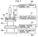
- Fig. 1 shows embodiment 1 where the present invention is utilised to fabricate a part.
- the present embodiment is structured by an object to be machined 103 immersed in a machining solution 102 within a machining solution container 101, a machining electrode 104 arranged oppositely to the object to be machined 103 to electrolytically machine the object to be machined 103, a reference electrode 105 as a reference in electrode potential, a potential/current control unit 106 for controlling the potential and current on the machining electrode 104, an XY-axis stage 107 for moving the object to be machined 103 in X-axis and Y-axis directions (horizontal directions), a z-axis stage installed beneath the machining solution container 101 to move the object to be machined 103 in a z-axis direction (vertical direction), a shape information memory unit 109 for memorising arbitrary shape information, a moving position control unit 110 for controlling the movement of the XY stage 107 and the z stage 108 based on the shape
- the potential/current control unit 106 is provided, for example, with a machining electrode circuit 106A called potentio galvanostat, a micro-computer for controlling the potential on the machining electrode 104 of the machining electrode circuit 106A and the current etc. flowing between the machining electrode 104 and the object to be machined 103, and various operating keys for operation.
- a machining electrode circuit 106A called potentio galvanostat
- a micro-computer for controlling the potential on the machining electrode 104 of the machining electrode circuit 106A and the current etc. flowing between the machining electrode 104 and the object to be machined 103, and various operating keys for operation.
- the machining electrode circuit 106A is structured, for example as shown in Fig. 2, by a variable resistance 202 connected to a plus side of a constant voltage power supply 201, an operational amplifier 203 connected to the variable resistance 202, an opposite electrode (machining electrode) 104 connected to an output section of the operational amplifier 203, an acting pole (object to be machined) 103 oppositely arranged to the opposite electrode (machining electrode) 104 and connected to a minus side of the constant voltage power supply 201, and a reference electrode 105 as a reference to measure the potential on the acting pole (object to be machined) 103.
- the machining electrode 104 is a rod form member sharp-edged at its tip opposite to a surface to be machined and exposed at only one portion of a tip end with other portions coated by an insulator. Also, the material of the rod member uses, for example, carbon, tungsten, platinum or the like.
- the reference electrode 105 is, for example, a glass cylindrical member having a solution passage provided at a tip on a side to be immersed in a machining solution and a silver thin wire provided in a centre of the cylindrical member to reach a glass film, wherein a silver chloride solution is filled in a manner immersing the thin wire.
- the reference electrode 105 is not required to control the potential on the machining electrode 104 and the object to be machined 103, i.e. it is not necessarily required when only performing current control between the machining electrode 104 and the object to be machined 103.
- this machining electrode circuit 106A it is possible to control the current flowing between the opposite electrode (machining electrode) 104 and the acting pole (object to be machined) 103 to a current required for electrolytic machining by varying the resistance value of the variable resistance 202.
- the XY-axis stage 107 and the Z-axis stage 108 are moved in the XY-axis direction and the Z-axis direction by an electrical drive means under the control of the moving position control unit 110.
- the Z-axis stage 108 is first moved in the Z-axis direction by a distance control means to control the space distance between the machining electrode 104 and the object to be machined 103 to a predetermined spacing, and then a predetermined voltage is applied between the machining electrode 104 and the object to be machined 103 to cause a constant current to flow between the machining electrode 104 and the object to be machined 103.
- the XY stage 107 and the Z-stage 108 are driven by the moving position control unit 110 based on shape information memorised by the shape information memory unit 109, in order to move the machining electrode along a shape of a part to be fabricated above the object to be machined.
- the above process is hereinafter referred to as an electrolytic machining process.
- the distance control means for example first controls, through the current/potential control unit 106. the current flowing between the object to be machined 103 and the machining electrode 104 to nearly zero, and then slowly moves the Z-axis stage upward to cause the object to be machined 103 to approach the machining electrode 104 while measuring the potential on the object to be measured. Because if the object to be machined 103 is brought into contact with the machining electrode 104 due to this ascending motion the potential of the object to be machined 103 greatly varies, the position on the Z-axis at this time is determined as the zero spacing position.
- the Z-axis stage 108 is driven under the control of the moving position control unit 110 to control the space distance between the machining electrode 104 and the object to be machined 103 to a desired spacing.
- a method can be considered that the space distance is measured by a laser measuring device.
- the machining solution changing mechanism 111 is structured, for example as shown in Fig. 3, by a machining solution tank (A) 302A containing a machining solution (A) 102A used when fabricating a cast mold by subjecting the object to be machined 103 to a removal process, a machining tank (B) 302B containing a machining solution (B) 102B used upon forming a metal layer, a machining solution tank (C) 302C containing a machining solution (C) 102C used upon forming a part, a machining solution tank (D) 302D containing a machining solution (D) 102D used upon dissolving a metal, a cleaning solution tank 303 containing a cleaning solution 301 used for cleaning the machining solution container 101 during changing the machining solution, a solution feed pump (A) 306A connected to the machining solution tank (A) 302A to feed the machining solution (A) 102A within the machining solution tank (A) 302A to the machining
- the machining solution changing mechanism 111 can supply a required amount of a solution from the tank containing a machining solution or cleaning solution required for machining to the machining solution container 101, and discharge the machining solution from the machining solution container 101.
- the solution feed pump (F) 308 is first driven to discharge the machining solution in the machining solution container 101 to the waste solution tank 304, as shown in Fig. 4. Then the solution feed pump (E) is driven to supply the cleaning solution 301 in the cleaning solution tank 303 to the machining solution container 101, and the solution feed pump (F) 308 is again driven to discharge the cleaning solution 31 in the machining solution container 101 into the waste solution tank 304.
- a solution feed pump which is connected to a machining solution tank containing a required machining solution among the machining solution (A) 102A, machining solution (B) 102B, machining solution (C) 102C and machining solution (D) 102D, is driven to supply the machining solution to the machining solution container 101.
- This process is hereinafter referred to as a machining solution changing process.
- the procedure of a part fabricating method according to the present embodiment will be explained hereinbelow based on Fig. 5 and Fig. 6.
- First the shape information for a part to be fabricated is memorised in the shape information memory unit 109.
- the machining solution (A) 102A as a machining solution for removal process is supplied into the machining solution container 101 by the machining solution changing mechanism 111.
- an object to be machined 103 shown in Fig. 6(a) is subjected to removal process, thus fabricating a cast mold 501 for parts as shown in Fig. 6(b).
- the machining solution in the machining solution container 101 is changed, through the aforesaid machining solution changing process, from the machining solution (A) 102A as a machining solution for removal process to a machining solution (B) 102B as a machining solution for forming a metal layer. Then an additional machining is performed through the aforesaid electrolyte machining to deposit a metal A on a surface of the cast mold 501 as shown in Fig. 6(C), thus forming a metal layer 502.
- the machining solution in the machining solution container 101 is changed. through the aforesaid machining solution changing process, from the machining solution (B) 102B as a machining solution for metal layer formation to a machining solution (C) 102C as a machining solution for electro-forming. Then additional machining is performed, through the electrolyte machining, on an inside of the cast mold 501 to deposit a metal B as shown in Fig. 6(d), thus forming a part 503.
- machining solution in the machining solution container 101 is changed, through the machining solution changing process, from the machining solution (C) 102C as a machining solution for electro-forming to a machining solution (D) 102D as a machining solution for metal layer dissolution to dissolve a metal layer 502 as shown in Fig. 6(e), removing the part 503 formed inside the cast mold 501.
- a method to dissolve the metal layer 502 is considered a method of using a solution for selectively dissolving only the metal A, a method applying a voltage to selectively dissolve only the metal A, or the like.
- the distance between the tip of the machining electrode and a surface to be machined of an object to be machined is controlled to a predetermined spacing by utilising a sharp-edged machining electrode, and thereafter machining is performed such that the machining electrode is moved along the shape of a part to be fabricated above a surface to be machined of the object to be machined, it is possible to fabricate simply a part having a complicated three dimensional form without the necessity of fabricating a machining electrode corresponding to a machining form. Also, because the machining is performed in a state of out of contact between the machining electrode and the object to be machined, there is less consumption of machining electrodes.
- the machining is performed by the electro-forming method utilising an electrochemical reaction, it is possible to perform machining with extremely low energy as compared with the electric discharge machining without changing the hardness and toughness of the object to be machined. Further, since the part fabricating apparatus in the present embodiment is provided with the machining solution changing mechanism, automation of part fabrication is readily realised.
- the machining electrode used was a platinum-iridium alloy wire sharp-edged at its tip to a tip diameter of 1 ⁇ m and coated by resin at other than the tip wherein a chromium substrate was used as an object to be machined.
- a chromium electrolytic etch solution mixed with 62.7 g/l of a sulfamic acid and 37.3 g/l of a boric acid was used as a machining solution for the removal process
- a gold plating solution mixed with 7.4g/l of potassium dicyanoaurarate (I) and 70 g/l of tri-sodium citrate as a machining solution for metal layer formation
- the procedure for fabricating a gear was performed along with a procedure shown in Fig. 5, wherein gear shape information was first memorised in a shape information memory unit 109, the chromium substrate was then subjected to the removal process to fabricate a gear cast mold, gold was then deposited on a surface of the cast mold, nickel was then deposited inside the cast mold to form the part, and finally the gold layer was dissolved to take the part out.
- a gold layer with a thickness of 2 ⁇ m was formed on the surface of the cast mold.
- the gold layer was dissolved by a gold etch solution with the result that a gear having a diameter of 800 ⁇ m and a thickness of 80 ⁇ m could be taken out.
- Embodiment 1 has a structure almost similar to Embodiment 1 as shown in Fig. 7, it is characterised in that the Z-axis stage 108 is arranged on the XY stage 107 and further the work electrode 104 is attached to the Z-axis stage 108 through a machining electrode attaching arm 113.
- the XY stage 107 moves in the XY directions and the Z-axis stage 108 in the Z-axis direction, causing the machining electrode 104 to follow the attaching arm 113 and hence move in the XY-axis directions and Z-axis direction.
- This also provides a similar effect to Embodiment 1.
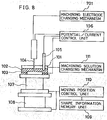
- Embodiment 1 is structured almost similar to Embodiment 1 as shown in Fig. 8, it is characterised in that a machining electrode changing mechanism 701 is arranged therein which can exchange the machining electrode for use in machining.
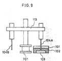
- the machining electrode changing mechanism 701 is provided with, for example as shown in Fig. 9, a machining electrode attaching arm 113 attached with machining electrode (104A) and machining electrode (104B) different in tip diameter, and an about-Z-axis rotation mechanism for rotating the machining electrode attaching arm about the Z-axis, so that the machining electrode to be used can be positioned above a surface to be machined of an object to be machined 103 immersed in a machining solution.
- the present embodiment can use a plurality of machining electrodes different in tip diameter, it is possible to select a machining electrode suitable for a shape of a portion to be machined or kind of machining.
- the present invention provides the following effects.
Landscapes
- Engineering & Computer Science (AREA)
- Chemical & Material Sciences (AREA)
- Mechanical Engineering (AREA)
- Chemical Kinetics & Catalysis (AREA)
- Electrochemistry (AREA)
- Materials Engineering (AREA)
- Metallurgy (AREA)
- Organic Chemistry (AREA)
- Physics & Mathematics (AREA)
- Thermal Sciences (AREA)
- Electrical Discharge Machining, Electrochemical Machining, And Combined Machining (AREA)
- Micromachines (AREA)
Applications Claiming Priority (2)
| Application Number | Priority Date | Filing Date | Title |
|---|---|---|---|
| JP33290297A JP3217999B2 (ja) | 1997-12-03 | 1997-12-03 | 部品製作方法及び部品製作装置 |
| JP33290297 | 1997-12-03 |
Publications (3)
| Publication Number | Publication Date |
|---|---|
| EP0920946A2 true EP0920946A2 (fr) | 1999-06-09 |
| EP0920946A3 EP0920946A3 (fr) | 2002-12-04 |
| EP0920946B1 EP0920946B1 (fr) | 2004-05-26 |
Family
ID=18260086
Family Applications (1)
| Application Number | Title | Priority Date | Filing Date |
|---|---|---|---|
| EP98309928A Expired - Lifetime EP0920946B1 (fr) | 1997-12-03 | 1998-12-03 | Méthode et appareil pour la fabrication d'une pièce |
Country Status (4)
| Country | Link |
|---|---|
| US (2) | US6221228B1 (fr) |
| EP (1) | EP0920946B1 (fr) |
| JP (1) | JP3217999B2 (fr) |
| DE (1) | DE69824125T2 (fr) |
Cited By (6)
| Publication number | Priority date | Publication date | Assignee | Title |
|---|---|---|---|---|
| US7097729B2 (en) | 1998-11-19 | 2006-08-29 | C.I.R.T.E.S. (Centre D'ingenierie De Recherche Et De Transfert De L'esstin A Saint-Die) | Method for making mechanical parts by decomposition into layers |
| SG155059A1 (en) * | 2003-06-11 | 2009-09-30 | Ishikawajima Harima Heavy Ind | Repair method for machine component, production method of restored machine component, production method of machine component, gas turbine engine, electric spark machine, repair method for turbine component and production method for restored turbine compo |
| US7607211B2 (en) * | 2000-05-15 | 2009-10-27 | Centre d'Ingéniérie de Recherche et de Transfert de l'Esstin à Saint Die (C.I.R.T.E.S.) | Device for producing plates designed for a fast prototyping process, method for machining and assembling said plates and resulting plates and prototype workpieces |
| US7920937B2 (en) | 2002-10-07 | 2011-04-05 | Cirtes SRC, SA Cooperative d'Ues | Mechanical component having at least one fluid transport circuit and method for designing same in strata |
| CN103894689A (zh) * | 2012-12-27 | 2014-07-02 | 财团法人金属工业研究发展中心 | 电加工方法与加工设备,以及应用于电加工的基准位置检测方法 |
| CN110842307A (zh) * | 2019-11-22 | 2020-02-28 | 合肥工业大学 | 一种针对可达性差复杂内壁结构的电解加工工具 |
Families Citing this family (10)
| Publication number | Priority date | Publication date | Assignee | Title |
|---|---|---|---|---|
| US6735844B2 (en) * | 2001-01-19 | 2004-05-18 | Honeywell International Inc. | Method for fabricating a plastic optic element injection mold |
| US6948240B2 (en) * | 2001-10-05 | 2005-09-27 | Benq Corporation | Method for shaping an object |
| US20050247569A1 (en) * | 2004-05-07 | 2005-11-10 | Lamphere Michael S | Distributed arc electroerosion |
| US7867374B2 (en) * | 2004-10-01 | 2011-01-11 | Federal-Mogul World Wide, Inc. | Active matrix electrochemical machining apparatus and method |
| DE102007043066A1 (de) * | 2007-09-10 | 2009-03-12 | Robert Bosch Gmbh | Verfahren und Vorrichtung zur elektrochemischen Bearbeitung |
| JP5423222B2 (ja) * | 2009-08-07 | 2014-02-19 | ソニー株式会社 | 位置検出装置および位置検出方法 |
| CN101880907B (zh) * | 2010-07-07 | 2012-04-25 | 厦门大学 | 纳米精度的电化学整平和抛光加工方法及其装置 |
| WO2015006647A1 (fr) * | 2013-07-12 | 2015-01-15 | The Regents Of The University Of Michigan | Adaptation de techniques d'électroformage pour la fabrication d'éléments de construction architecturaux |
| WO2016085782A1 (fr) | 2014-11-26 | 2016-06-02 | Corning Incorporated | Appareil et procédé pour réaliser des filières d'extrusion |
| CN113510325B (zh) * | 2021-07-05 | 2022-08-09 | 河南理工大学 | 一种用于射流电解加工的对刀装置 |
Family Cites Families (25)
| Publication number | Priority date | Publication date | Assignee | Title |
|---|---|---|---|---|
| US3723695A (en) * | 1971-12-17 | 1973-03-27 | Budd Co | Edm electrode |
| GB1500174A (en) * | 1975-05-23 | 1978-02-08 | Volvo Ab | Method for the production of forming tools for deep drawing moulding extruding and the like |
| JPS5213436A (en) | 1975-07-24 | 1977-02-01 | Toppan Printing Co Ltd | Production method for metal mesh plate |
| DE2944505C2 (de) * | 1979-11-03 | 1985-09-05 | Aeg-Elotherm Gmbh, 5630 Remscheid | Verfahren zur elektrochemischen Bearbeitung eines metallenen Werkstückes und Einrichtung zur Durchführung dieses Verfahrens |
| DE2950998A1 (de) * | 1980-01-09 | 1981-06-25 | Eksperimental'nyj naučno-issledovatel'skij institut metallorežuščich stankov, Moskva | Elektrochemisches bearbeitungsverfahren fuer werkstuecke und einrichtung zu dessen verwirklichung |
| US4425197A (en) * | 1981-08-19 | 1984-01-10 | Inoue-Japax Research Incorporated | Method of and apparatus for electrodepositing a metal on a conductive surface |
| JP2670576B2 (ja) | 1987-04-21 | 1997-10-29 | 旭化成工業株式会社 | 電子写真感光体 |
| FR2624791B1 (fr) * | 1987-12-21 | 1993-08-13 | Banque De France | Procede de fabrication en serie d'elements d'impression en taille-douce en acier, et appareil pour la mise en oeuvre du procede |
| JPH0273987A (ja) | 1988-09-09 | 1990-03-13 | Seiko Epson Corp | スタンパの複製方法 |
| JPH0678590B2 (ja) * | 1988-09-19 | 1994-10-05 | パイオニア株式会社 | スタンパー製造方法 |
| US4964945A (en) | 1988-12-09 | 1990-10-23 | Minnesota Mining And Manufacturing Company | Lift off patterning process on a flexible substrate |
| DE3937308C1 (fr) * | 1989-11-09 | 1991-03-21 | Kernforschungszentrum Karlsruhe Gmbh, 7500 Karlsruhe, De | |
| KR910018111A (ko) * | 1990-04-26 | 1991-11-30 | 시기 모리야 | 전해가공방법 및 전해가공장치 |
| JP2952539B2 (ja) | 1992-03-30 | 1999-09-27 | セイコーインスツルメンツ株式会社 | 微細加工装置 |
| JP3041740B2 (ja) | 1992-03-31 | 2000-05-15 | セイコーインスツルメンツ株式会社 | 微細加工方法 |
| JP3261471B2 (ja) | 1992-07-16 | 2002-03-04 | 九州日立マクセル株式会社 | メタルマスクの製造方法 |
| US5320721A (en) * | 1993-01-19 | 1994-06-14 | Corning Incorporated | Shaped-tube electrolytic polishing process |
| US5441626A (en) * | 1993-04-09 | 1995-08-15 | Toyoda Gosei Co., Ltd. | Partially plated resin products and partial plating process therefor |
| JP2879643B2 (ja) | 1994-08-08 | 1999-04-05 | セイコーインスツルメンツ株式会社 | フォトリソグラフィ用マスクの修正方法 |
| US5879520A (en) * | 1994-08-26 | 1999-03-09 | Griego; Thomas P. | Rotary electrodeposition apparatus |
| US5750014A (en) * | 1995-02-09 | 1998-05-12 | International Hardcoat, Inc. | Apparatus for selectively coating metal parts |
| JPH08227007A (ja) | 1995-02-21 | 1996-09-03 | Olympus Optical Co Ltd | 物体の表面形状生成方法および金型の製造方法 |
| US5641391A (en) * | 1995-05-15 | 1997-06-24 | Hunter; Ian W. | Three dimensional microfabrication by localized electrodeposition and etching |
| JP3783030B2 (ja) | 1996-05-07 | 2006-06-07 | 九州日立マクセル株式会社 | 微細孔抜き用金型の製造方法 |
| US5976340A (en) * | 1997-10-28 | 1999-11-02 | Lockheed Martin Corporation | Method of fabricating elevated temperature application parts with a serrated surface |
-
1997
- 1997-12-03 JP JP33290297A patent/JP3217999B2/ja not_active Expired - Fee Related
-
1998
- 1998-12-02 US US09/204,636 patent/US6221228B1/en not_active Expired - Lifetime
- 1998-12-03 EP EP98309928A patent/EP0920946B1/fr not_active Expired - Lifetime
- 1998-12-03 DE DE69824125T patent/DE69824125T2/de not_active Expired - Lifetime
-
2001
- 2001-01-19 US US09/765,549 patent/US6589402B2/en not_active Expired - Lifetime
Cited By (8)
| Publication number | Priority date | Publication date | Assignee | Title |
|---|---|---|---|---|
| US7097729B2 (en) | 1998-11-19 | 2006-08-29 | C.I.R.T.E.S. (Centre D'ingenierie De Recherche Et De Transfert De L'esstin A Saint-Die) | Method for making mechanical parts by decomposition into layers |
| US7607211B2 (en) * | 2000-05-15 | 2009-10-27 | Centre d'Ingéniérie de Recherche et de Transfert de l'Esstin à Saint Die (C.I.R.T.E.S.) | Device for producing plates designed for a fast prototyping process, method for machining and assembling said plates and resulting plates and prototype workpieces |
| US7920937B2 (en) | 2002-10-07 | 2011-04-05 | Cirtes SRC, SA Cooperative d'Ues | Mechanical component having at least one fluid transport circuit and method for designing same in strata |
| SG155059A1 (en) * | 2003-06-11 | 2009-09-30 | Ishikawajima Harima Heavy Ind | Repair method for machine component, production method of restored machine component, production method of machine component, gas turbine engine, electric spark machine, repair method for turbine component and production method for restored turbine compo |
| US7723636B2 (en) | 2003-06-11 | 2010-05-25 | Ishikawajima-Harima Heavy Industries Co., Ltd. | Method for repairing machine part, method for forming restored machine part, method for manufacturing machine part, gas turbine engine, electric discharge machine, method for repairing turbine component, and method for forming restored turbine component |
| CN103894689A (zh) * | 2012-12-27 | 2014-07-02 | 财团法人金属工业研究发展中心 | 电加工方法与加工设备,以及应用于电加工的基准位置检测方法 |
| CN103894689B (zh) * | 2012-12-27 | 2016-03-02 | 财团法人金属工业研究发展中心 | 电加工方法与加工设备,以及应用于电加工的基准位置检测方法 |
| CN110842307A (zh) * | 2019-11-22 | 2020-02-28 | 合肥工业大学 | 一种针对可达性差复杂内壁结构的电解加工工具 |
Also Published As
| Publication number | Publication date |
|---|---|
| US20010002001A1 (en) | 2001-05-31 |
| US6221228B1 (en) | 2001-04-24 |
| EP0920946A3 (fr) | 2002-12-04 |
| DE69824125D1 (de) | 2004-07-01 |
| JP3217999B2 (ja) | 2001-10-15 |
| DE69824125T2 (de) | 2005-06-23 |
| JPH11158682A (ja) | 1999-06-15 |
| US6589402B2 (en) | 2003-07-08 |
| EP0920946B1 (fr) | 2004-05-26 |
Similar Documents
| Publication | Publication Date | Title |
|---|---|---|
| EP0920946B1 (fr) | Méthode et appareil pour la fabrication d'une pièce | |
| EP0699782A1 (fr) | Enlêvement électrochimique de métal à grande vitesse en vue de la planification d'une structure DLM utilisant un électrolyte salin neutre | |
| CN112334310A (zh) | 用于三维结构体的连续电化学制造的方法和设备 | |
| Choi et al. | Fabrication of WC micro-shaft by using electrochemical etching | |
| Davydov et al. | Electrochemical local maskless micro/nanoscale deposition, dissolution, and oxidation of metals and semiconductors (a review) | |
| Debnath et al. | Wire electrochemical machining process: overview and recent advances | |
| Vasyliev et al. | Influence of polarization curve slope on the accuracy of local copper electrodeposition from sulphate electrolyte | |
| Guo et al. | Electrochemical surface smoothing of spark erosion treated Zr-based bulk metallic glasses in NaCl-ethylene glycol electrolyte | |
| Kumar et al. | Fabrication of microtool for micromachining: A review | |
| Rosso et al. | Shape evolution of metals electrodeposited from binary electrolytes | |
| KR20230134415A (ko) | 반도체 피처들을 형성하기 위한 전기 화학적 어셈블리 | |
| JP4448271B2 (ja) | 部品製造方法及び部品製造装置 | |
| US20220364252A1 (en) | Methods for manufacturing metallic cutting edge through electrodeposition | |
| US3202595A (en) | Electro-chemical machining process | |
| KR100379748B1 (ko) | 초미세 원통형 전극제작을 위한 전해가공방법 | |
| JP3750268B2 (ja) | 放電加工用工具電極の製造方法 | |
| JP3354890B2 (ja) | 加工方法および加工装置 | |
| RU2704363C1 (ru) | Аппарат для электрохимического получения слоистых металлических нанопроводов | |
| Rathod et al. | Electrochemical Micromachining (EMM): Fundamentals and Applications | |
| Lipiec | Localized electrochemical deposition–preliminary research | |
| Pandey et al. | An optimal toolpath planning for realizing 3D micro metallic features via selective jet electrodeposition (SJED) process | |
| JP2000202718A (ja) | 加工工具用電極の製造方法及び加工方法 | |
| JP3002981B1 (ja) | 加工方法および加工装置 | |
| Swain | Preparation of coated microtools for electrochemical machining applications | |
| Shengyuan et al. | Research on “slice” layer height and width additive manufacturing by maskless localized electrodeposition method |
Legal Events
| Date | Code | Title | Description |
|---|---|---|---|
| PUAI | Public reference made under article 153(3) epc to a published international application that has entered the european phase |
Free format text: ORIGINAL CODE: 0009012 |
|
| AK | Designated contracting states |
Kind code of ref document: A2 Designated state(s): AT BE CH CY DE DK ES FI FR GB GR IE IT LI LU MC NL PT SE |
|
| AX | Request for extension of the european patent |
Free format text: AL;LT;LV;MK;RO;SI |
|
| PUAL | Search report despatched |
Free format text: ORIGINAL CODE: 0009013 |
|
| AK | Designated contracting states |
Kind code of ref document: A3 Designated state(s): AT BE CH CY DE DK ES FI FR GB GR IE IT LI LU MC NL PT SE |
|
| AX | Request for extension of the european patent |
Free format text: AL;LT;LV;MK;RO;SI |
|
| RIC1 | Information provided on ipc code assigned before grant |
Free format text: 7B 23H 9/00 A, 7B 23H 1/00 B, 7C 25D 1/20 B, 7B 23P 15/24 B, 7B 29C 33/38 B, 7B 23H 3/00 B, 7B 23H 5/00 B |
|
| 17P | Request for examination filed |
Effective date: 20030429 |
|
| AKX | Designation fees paid |
Designated state(s): DE GB |
|
| GRAP | Despatch of communication of intention to grant a patent |
Free format text: ORIGINAL CODE: EPIDOSNIGR1 |
|
| GRAS | Grant fee paid |
Free format text: ORIGINAL CODE: EPIDOSNIGR3 |
|
| GRAA | (expected) grant |
Free format text: ORIGINAL CODE: 0009210 |
|
| AK | Designated contracting states |
Kind code of ref document: B1 Designated state(s): DE GB |
|
| REG | Reference to a national code |
Ref country code: GB Ref legal event code: FG4D |
|
| REG | Reference to a national code |
Ref country code: IE Ref legal event code: FG4D |
|
| REF | Corresponds to: |
Ref document number: 69824125 Country of ref document: DE Date of ref document: 20040701 Kind code of ref document: P |
|
| PLBE | No opposition filed within time limit |
Free format text: ORIGINAL CODE: 0009261 |
|
| STAA | Information on the status of an ep patent application or granted ep patent |
Free format text: STATUS: NO OPPOSITION FILED WITHIN TIME LIMIT |
|
| 26N | No opposition filed |
Effective date: 20050301 |
|
| PGFP | Annual fee paid to national office [announced via postgrant information from national office to epo] |
Ref country code: GB Payment date: 20141203 Year of fee payment: 17 Ref country code: DE Payment date: 20141125 Year of fee payment: 17 |
|
| REG | Reference to a national code |
Ref country code: DE Ref legal event code: R119 Ref document number: 69824125 Country of ref document: DE |
|
| GBPC | Gb: european patent ceased through non-payment of renewal fee |
Effective date: 20151203 |
|
| PG25 | Lapsed in a contracting state [announced via postgrant information from national office to epo] |
Ref country code: GB Free format text: LAPSE BECAUSE OF NON-PAYMENT OF DUE FEES Effective date: 20151203 Ref country code: DE Free format text: LAPSE BECAUSE OF NON-PAYMENT OF DUE FEES Effective date: 20160701 |