EP0921088B1 - Ascenseur avec contrôleur de déplacement embarqué sur la cabine - Google Patents
Ascenseur avec contrôleur de déplacement embarqué sur la cabine Download PDFInfo
- Publication number
- EP0921088B1 EP0921088B1 EP98123102A EP98123102A EP0921088B1 EP 0921088 B1 EP0921088 B1 EP 0921088B1 EP 98123102 A EP98123102 A EP 98123102A EP 98123102 A EP98123102 A EP 98123102A EP 0921088 B1 EP0921088 B1 EP 0921088B1
- Authority
- EP
- European Patent Office
- Prior art keywords
- control unit
- cabin
- lift
- elevator
- shaft
- Prior art date
- Legal status (The legal status is an assumption and is not a legal conclusion. Google has not performed a legal analysis and makes no representation as to the accuracy of the status listed.)
- Expired - Lifetime
Links
- 238000006073 displacement reaction Methods 0.000 title 1
- 238000012423 maintenance Methods 0.000 description 3
- 230000008054 signal transmission Effects 0.000 description 3
- 210000004556 brain Anatomy 0.000 description 2
- 230000006870 function Effects 0.000 description 2
- 238000000034 method Methods 0.000 description 2
- 238000011109 contamination Methods 0.000 description 1
- 230000007547 defect Effects 0.000 description 1
- 230000005611 electricity Effects 0.000 description 1
- 230000005855 radiation Effects 0.000 description 1
- 238000002604 ultrasonography Methods 0.000 description 1
Images
Classifications
-
- B—PERFORMING OPERATIONS; TRANSPORTING
- B66—HOISTING; LIFTING; HAULING
- B66B—ELEVATORS; ESCALATORS OR MOVING WALKWAYS
- B66B11/00—Main component parts of lifts in, or associated with, buildings or other structures
- B66B11/0035—Arrangement of driving gear, e.g. location or support
- B66B11/0045—Arrangement of driving gear, e.g. location or support in the hoistway
Definitions
- the invention relates to an elevator, with one in one Shaft moving cabin, a stationary on or in Shaft mounted drive unit, electrical input devices on the shaft doors for entering Request signals and with a driving program control unit, which processes the request and target signals and depending on it the schedule of the cabin certainly.
- the travel program control unit is usually used for elevators (Control) that the travel of the elevator car controls, housed in the same machine room, in where the drive unit is located.
- the spatial Proximity of the control unit (control) to the drive unit has the advantage that the controlling unit is close the controlled unit is arranged, and that between both only short lines are required.
- a modular elevator system is known from US 4,896,747. where a control module is attached to the cabin is, while shaft modules in the course of the elevator shaft are provided.
- the cabin control module carries the floor display and the cabin side Dialpad. The modules work together to operate the door and control the cabin position. About the Driving program control of the elevator is not specified made.
- An elevator control is known from DE 295 03 121 U, where a stationary control part for control and Regulation of stationary elevator components is available and a control part connected to the cabin Control and regulation of cabin-related components, such as. Sensors, actuators or human-machine interfaces, such as displays or controls.
- the driving program is controlled in a conventional manner Way through the stationary control part.
- the invention has for its object an elevator to create with a fixed drive unit, in which the Accessibility of the control unit is improved.
- the travel program control unit arranged separately from the drive unit. While the drive unit on or in the shaft is attached, the drive program control unit is located traveling with the cabin. This has the advantage that the control unit is very easily accessible.
- the Maintenance technician does not need to be in a separate one Machine room or even into the elevator shaft.
- the driving program control unit located on the cabin is accessible where the cabin is located. So the cabin can be any Floor to be driven for maintenance or repair work perform. If the elevator is due to Defect is no longer controllable, the cabin can Release the brake to the next floor, where it can then be entered by the fitter.
- the driving program control unit is the control unit depending on request and target signals, arranged around the most diverse Input devices of the elevator system entered as well as depending on the current location of the elevator creates the travel program.
- the drive program control unit forms the central "brain" of the elevator. It can also control other functions, such as opening the cabin side Door and the shaft-side door.
- the drive program control unit not only defines the driving program, but also it collects all the commands and checks whether the security circles are closed, which is a prerequisite for that the cabin can drive.
- the operating control of the drive unit takes place expediently via a motor control unit which is arranged in a stationary manner, preferably spatially Near the drive unit.
- the engine control unit controls the engine speed depending on the Command signals they from the drive program control unit receives.
- the engine control unit contains a tachometer or tachometer Determination of the actual speed. It also contains one Speeds memory in which speeds are stored, for example a start-up characteristic and a braking characteristic to give a smooth Run up and slow down the cabin.
- Speeds memory in which speeds are stored, for example a start-up characteristic and a braking characteristic to give a smooth Run up and slow down the cabin.
- the control of a converter takes place Motor of the drive unit with a corresponding frequency supplied, which specifies the desired speed.
- the motor control unit contains one containing the converter Has power section, which high currents more variable It delivers frequency for the electric motor cheap if that from the engine control unit to the Motor leading cables are short to high frequency contamination to avoid as far as possible by radiation from the cable. Therefore, the power control of the engine is from the driving program control is spatially separated. About the Tow cables leading to the cabin are used exclusively Transfer data and electricity for cabin lighting etc..
- the driving program control unit is preferably from Interior of the cabin accessible from. Here you can a door or hatch are located with a key can be opened to access the control unit to obtain. Such a control unit is for the fitter very easy and convenient to reach.
- the driving program control unit is also within the scope of the invention to be installed elsewhere in the cabin, for example on the cabin roof.
- the invention is a first flexible cable provided that of those on each floor installed input devices leads to the cabin.
- a second flexible cable is also provided leads from the cabin to the drive unit.
- the first and the second cable are looped single cable harness summarized. Thereby it is avoided that numerous independent from each other Hang cable loops in the elevator shaft.
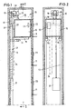
- the elevator shown has an elevator shaft 10 on, each with a Door opening 11 is provided.
- a frame 12 is mounted, which vertical rails 13 for guiding a carriage 14.
- the frame 12 is located on the side facing away from the door openings 11 Rear wall or on a side wall of the shaft 10th
- the carriage 14 has one transversely in the shaft 10 protruding cantilever arm 15 on which the cabin 16 rests.
- the car 16 is a common elevator car, which can accommodate several people and which has a tableau Contains 17 with input keys that the user can enter the desired floor.
- the carriage 14 hangs on a rope 18, which over the traction sheave 19 of a drive unit 20 runs.
- the Drive unit 20 includes an electric motor 28 which the traction sheave 19 rotates. As a result, the rope 18 of the traction sheave 19 moves up or down.
- the rope wraps around the traction sheave 19 in a groove and be opposite end is with a counterweight 21 complained that hangs in the shaft.
- the drive unit 20 is operated by a driving program control unit 22 controlled in or on the cabin 16 is arranged.
- the driving program control unit 22 forms the "brain" of the elevator. It receives request signals of input devices 23 to the Door openings 11 are installed, and command or Target signals from the panel 17 inside the cabin 16. Depending on these request and target signals the driving program control unit sets the sequence in which the cabin moves to the individual floors.
- the drive program control unit 22 controls the Drive unit 20.
- the cable harness 24 contains a first cable 25 from the input devices 23 leads to the driving program control unit 22, and a second cable 26 from the drive program control unit 22 leads to the drive unit 20.
- the wiring harness 24 can still supply lines and other lines included.
- the driving program control unit 22 is in the present Embodiment housed in a box 27, which is arranged on the outside of the cabin 16 and that from inside the cabin through a flap or door is accessible.
- the control unit can also be arranged elsewhere, for example under the cabin floor or on the cabin roof.
- the stationary in the upper area of the elevator shaft 10 arranged drive unit 20 contains in addition to the electric motor 28 also the motor control unit 29, which in the immediate vicinity of the electric motor 28 is arranged.
- the motor control unit 29 contains a converter that the three-phase three-phase current required for the motor 28 generated. The three-phase frequency varies accordingly the desired engine speed.
- the engine control unit 29 receives the signals via the cable 26 Input devices 23 and the drive program control unit 22. From the signals of the soon to be controlled Stop positions and the actual position of the elevator car it determines the required speed. she also contains a speed memory for Control of the start-up and braking process.
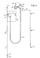
- FIG. 3 shows a schematic image of the cabin control, with those on the different floors installed input devices 23, the in the elevator car 16 located tableau 17 and the stationary Drive unit 20.
- a in the elevator shaft Position measuring system 30 installed, which consists of a Signal wire 31 and an ultrasonic transmitter 32 is made.
- the ultrasound transmitter 32 the on the cabin 16 is arranged, sets ultrasonic pulses on the signal wire. Based on the transit times of the ultrasonic pulses the actual position of the cabin 16 is determined and depending on this, the Drive program control unit 22, the drive unit 20 in controlled in such a way that the floors with high accuracy be approached.
- a tachometer 36 is also shown, which determines the actual speed of the motor 28 and to the Engine control unit 29 delivers.
- the Signal transmission from and to the drive program control unit 22 via the cables 25, 26 there is also Possibility instead of a wired signal transmission to provide wireless signal transmission.
Landscapes
- Engineering & Computer Science (AREA)
- Civil Engineering (AREA)
- Mechanical Engineering (AREA)
- Structural Engineering (AREA)
- Elevator Control (AREA)
- Types And Forms Of Lifts (AREA)
- Valve-Gear Or Valve Arrangements (AREA)
- Valve Device For Special Equipments (AREA)
Claims (6)
- Ascenseur comportant une cabine (16) se déplaçant dans une cage (10), une unité d'entraínement (20) disposée fixement sur ou dans la cage (10), des dispositifs électriques d'entrée (23) sur les portes de la cage pour l'entrée de signaux d'appel, et une unité de commande du programme de déplacement (22), qui traite les signaux d'appel et de destination et, en fonction de ceux-ci, détermine le plan de déplacement de la cabine,
caractérisé en ce que
l'unité de commande du programme de déplacement (22) est disposée sur la cabine (16) de manière à se déplacer avec celle-ci. - Ascenseur selon la revendication 1, caractérisé en ce que l'unité d'entraínement (20) présente une unité de commande de moteur (29) pour la commande du moteur (28).
- Ascenseur selon la revendication 2, caractérisé en ce que l'unité de commande de moteur (29) comprend un convertisseur de fréquence et un enregistreur de vitesses et la fréquence fournie par le convertisseur de fréquence varie selon les signaux d'instructions de l'unité de commande du programme de déplacement en fonction de la vitesse réelle du moteur (28).
- Ascenseur selon l'une quelconque des revendications 1 à 3, caractérisé en ce que l'unité de commande (22) est accessible de l'intérieur de la cabine (16).
- Ascenseur selon l'une quelconque des revendications 1 à 4, caractérisé en ce que l'unité de commande (22) est logée dans une boíte (27) prévue à l'extérieur sur la cabine et accessible de l'intérieur de la cabine.
- Ascenseur selon l'une quelconque des revendications 1 à 5, caractérisé en ce qu'un premier câble flexible (25) mène depuis les dispositifs d'entrée (23) jusqu'à la cabine (16), qu'un second câble flexible (26) mène depuis la cabine (16) portant l'unité de commande jusqu'à l'unité d'entraínement (20) ou à l'unité de commande de moteur (29), et en ce que le premier et le second câbles (25, 26) sont réunis en un seul faisceau de câbles (24) sur une partie de leur longueur formant une boucle.
Applications Claiming Priority (2)
| Application Number | Priority Date | Filing Date | Title |
|---|---|---|---|
| DE19754036 | 1997-12-05 | ||
| DE19754036A DE19754036A1 (de) | 1997-12-05 | 1997-12-05 | Aufzug |
Publications (2)
| Publication Number | Publication Date |
|---|---|
| EP0921088A1 EP0921088A1 (fr) | 1999-06-09 |
| EP0921088B1 true EP0921088B1 (fr) | 2003-05-14 |
Family
ID=7850885
Family Applications (1)
| Application Number | Title | Priority Date | Filing Date |
|---|---|---|---|
| EP98123102A Expired - Lifetime EP0921088B1 (fr) | 1997-12-05 | 1998-12-03 | Ascenseur avec contrôleur de déplacement embarqué sur la cabine |
Country Status (2)
| Country | Link |
|---|---|
| EP (1) | EP0921088B1 (fr) |
| DE (3) | DE19754036A1 (fr) |
Families Citing this family (7)
| Publication number | Priority date | Publication date | Assignee | Title |
|---|---|---|---|---|
| WO2001028910A1 (fr) * | 1999-10-22 | 2001-04-26 | Mitsubishi Denki Kabushiki Kaisha | Logique de commande d'ascenseur |
| US6892862B2 (en) | 2000-07-29 | 2005-05-17 | Alpha Getriebebau Gmbh | Elevator car with a driving pulley driving machine integrated therein |
| FR2822143A1 (fr) * | 2001-03-19 | 2002-09-20 | Nk System Nv | Controleur de manoeuvre pour ascenseurs a regulation embarquee |
| FR2822144A1 (fr) * | 2001-03-19 | 2002-09-20 | Nk System Nv | Controleur de manoeuvre pour ascenseurs a capteurs embarques |
| JPWO2005085113A1 (ja) * | 2004-03-02 | 2007-08-30 | 三菱電機株式会社 | エレベータ制御装置 |
| DE102005002607A1 (de) * | 2005-01-20 | 2006-08-10 | System Antriebstechnik Dresden Gmbh | Treibscheibenaufzug |
| EP4269313A1 (fr) | 2022-04-25 | 2023-11-01 | Thoma Aufzüge GmbH | Ascenseur universel |
Family Cites Families (9)
| Publication number | Priority date | Publication date | Assignee | Title |
|---|---|---|---|---|
| DE1033383B (de) | 1956-12-21 | 1958-07-03 | Stahl Maschinenfabrik R | Triebwerk fuer Aufzuege, insbesondere Kleinlastenaufzuege |
| CH615138A5 (en) | 1977-11-18 | 1980-01-15 | Julio Villars | Load elevator |
| JPS644783Y2 (fr) | 1980-06-02 | 1989-02-07 | ||
| DE8434382U1 (de) * | 1984-11-23 | 1985-05-30 | Rösch, Wolfgang, Dipl.-Ing., 8399 Ruhstorf | Elektronischer aufzugantrieb |
| ES2042805T3 (es) * | 1988-03-03 | 1993-12-16 | Schaffer Dagmar | Ascensor sin cuarto de maquinas. |
| US4896747A (en) * | 1988-07-28 | 1990-01-30 | Otis Elevator Company | Modular elevator system |
| DE29503121U1 (de) * | 1995-02-24 | 1995-04-20 | Siemens AG, 80333 München | Steuerung für eine Kabine, Transportplattform o.ä. eines Aufzugs |
| FI103498B (fi) * | 1996-09-05 | 1999-07-15 | Kone Corp | Järjestely hissikoneiston jarrun avaamiseen |
| EP0870721B1 (fr) * | 1997-04-11 | 2003-01-22 | Inventio Ag | Ascenseur avec armoire de contrôle |
-
1997
- 1997-12-05 DE DE19754036A patent/DE19754036A1/de not_active Withdrawn
-
1998
- 1998-12-03 EP EP98123102A patent/EP0921088B1/fr not_active Expired - Lifetime
- 1998-12-03 DE DE59808347T patent/DE59808347D1/de not_active Expired - Fee Related
- 1998-12-04 DE DE29821667U patent/DE29821667U1/de not_active Expired - Lifetime
Also Published As
| Publication number | Publication date |
|---|---|
| EP0921088A1 (fr) | 1999-06-09 |
| DE19754036A1 (de) | 1999-06-10 |
| DE59808347D1 (de) | 2003-06-18 |
| DE29821667U1 (de) | 1999-02-25 |
Similar Documents
| Publication | Publication Date | Title |
|---|---|---|
| DE69932949T3 (de) | Aufzugssteuerung | |
| DE69927565T2 (de) | Anordnung des Steuerungssystemes | |
| EP3478617B1 (fr) | Ascenseur | |
| DE69517915T3 (de) | Antriebsscheibenaufzug | |
| EP1246770B1 (fr) | Trou d'inspection d'une cabine d'ascenseur | |
| DE69519364T2 (de) | Treibscheibenaufzug und Maschinenraum für einen Treibscheibenaufzug | |
| EP1119512B1 (fr) | Ascenseur pourvu d'un dispositif d'intervention en regime special | |
| DE29615921U1 (de) | Anordnung zum Lösen der Bremse einer Aufzugmaschine | |
| EP1319624A1 (fr) | Dispositif et méthode pour la modernisation d'ascenseur | |
| EP0987211A1 (fr) | Commande à distance pour installation d'ascenseur | |
| EP0565893A2 (fr) | Entraînement pour ascenseurs à câbles | |
| WO2010072658A1 (fr) | Système d'ascenseur présentant un dispositif de sécurité | |
| DE69926988T2 (de) | Aufzugsystem mit an der Schachttür anliegendem Antrieb | |
| EP0921088A1 (fr) | Ascenseur avec contrÔleur de déplacement embarqué sur la cabine | |
| DE4119253C2 (fr) | ||
| EP0926093B1 (fr) | Ascenseur, en particulier ascenseur à poulie | |
| EP2497739A1 (fr) | Ascenseur | |
| EP1251226A2 (fr) | Système de lève-vitre et méthode pour contrôler une pluralité de lève-vitres | |
| EP0979205A1 (fr) | Ascenseur a commande par cable | |
| DE60115024T2 (de) | Zyklisch betriebener aufzug | |
| EP0982258A1 (fr) | Dispositif pour générer des informations de cage dans une installation d'ascenseur | |
| EP1894876A1 (fr) | Dispositif d'élévation doté d'une cabine et d'un contrepoids et procédé destiné à la disposition d'une installation d'élévation | |
| EP1918238A1 (fr) | Ascenseur doté de deux cabines superposées dans une gaine | |
| DE202022106610U1 (de) | Aufzugsanlage mit einem Gehäuse in einem Seitenpfosten einer Schachttür | |
| EP3898488B1 (fr) | Système de commande de porte pour une installation d'ascenseur |
Legal Events
| Date | Code | Title | Description |
|---|---|---|---|
| PUAI | Public reference made under article 153(3) epc to a published international application that has entered the european phase |
Free format text: ORIGINAL CODE: 0009012 |
|
| AK | Designated contracting states |
Kind code of ref document: A1 Designated state(s): BE DE LU NL |
|
| AX | Request for extension of the european patent |
Free format text: AL;LT;LV;MK;RO;SI |
|
| 17P | Request for examination filed |
Effective date: 19991209 |
|
| AKX | Designation fees paid |
Free format text: BE DE LU NL |
|
| GRAG | Despatch of communication of intention to grant |
Free format text: ORIGINAL CODE: EPIDOS AGRA |
|
| 17Q | First examination report despatched |
Effective date: 20011221 |
|
| GRAG | Despatch of communication of intention to grant |
Free format text: ORIGINAL CODE: EPIDOS AGRA |
|
| GRAH | Despatch of communication of intention to grant a patent |
Free format text: ORIGINAL CODE: EPIDOS IGRA |
|
| GRAH | Despatch of communication of intention to grant a patent |
Free format text: ORIGINAL CODE: EPIDOS IGRA |
|
| GRAA | (expected) grant |
Free format text: ORIGINAL CODE: 0009210 |
|
| AK | Designated contracting states |
Designated state(s): BE DE LU NL |
|
| REF | Corresponds to: |
Ref document number: 59808347 Country of ref document: DE Date of ref document: 20030618 Kind code of ref document: P |
|
| PLBE | No opposition filed within time limit |
Free format text: ORIGINAL CODE: 0009261 |
|
| STAA | Information on the status of an ep patent application or granted ep patent |
Free format text: STATUS: NO OPPOSITION FILED WITHIN TIME LIMIT |
|
| 26N | No opposition filed |
Effective date: 20040217 |
|
| PGFP | Annual fee paid to national office [announced via postgrant information from national office to epo] |
Ref country code: NL Payment date: 20060627 Year of fee payment: 8 Ref country code: LU Payment date: 20060627 Year of fee payment: 8 Ref country code: DE Payment date: 20060627 Year of fee payment: 8 Ref country code: BE Payment date: 20060627 Year of fee payment: 8 |
|
| PG25 | Lapsed in a contracting state [announced via postgrant information from national office to epo] |
Ref country code: BE Free format text: LAPSE BECAUSE OF NON-PAYMENT OF DUE FEES Effective date: 20061231 |
|
| PG25 | Lapsed in a contracting state [announced via postgrant information from national office to epo] |
Ref country code: NL Free format text: LAPSE BECAUSE OF NON-PAYMENT OF DUE FEES Effective date: 20070701 |
|
| PG25 | Lapsed in a contracting state [announced via postgrant information from national office to epo] |
Ref country code: DE Free format text: LAPSE BECAUSE OF NON-PAYMENT OF DUE FEES Effective date: 20070703 |
|
| NLV4 | Nl: lapsed or anulled due to non-payment of the annual fee |
Effective date: 20070701 |
|
| BERE | Be: lapsed |
Owner name: L. *HOPMANN MASCHINENFABRIK G.M.B.H. Effective date: 20061231 |
|
| PG25 | Lapsed in a contracting state [announced via postgrant information from national office to epo] |
Ref country code: LU Free format text: LAPSE BECAUSE OF NON-PAYMENT OF DUE FEES Effective date: 20061203 |