EP0921246A2 - Construction de sous-toiture variable pour toit à forte pente - Google Patents
Construction de sous-toiture variable pour toit à forte pente Download PDFInfo
- Publication number
- EP0921246A2 EP0921246A2 EP98122672A EP98122672A EP0921246A2 EP 0921246 A2 EP0921246 A2 EP 0921246A2 EP 98122672 A EP98122672 A EP 98122672A EP 98122672 A EP98122672 A EP 98122672A EP 0921246 A2 EP0921246 A2 EP 0921246A2
- Authority
- EP
- European Patent Office
- Prior art keywords
- roof construction
- carrier
- system carrier
- fixing plates
- head
- Prior art date
- Legal status (The legal status is an assumption and is not a legal conclusion. Google has not performed a legal analysis and makes no representation as to the accuracy of the status listed.)
- Withdrawn
Links
- 238000010276 construction Methods 0.000 title claims description 5
- 238000009413 insulation Methods 0.000 claims abstract description 21
- 239000000969 carrier Substances 0.000 claims description 3
- 239000006260 foam Substances 0.000 description 4
- 210000001503 joint Anatomy 0.000 description 2
- 239000000463 material Substances 0.000 description 2
- 239000002184 metal Substances 0.000 description 1
Images

Classifications
-
- E—FIXED CONSTRUCTIONS
- E04—BUILDING
- E04D—ROOF COVERINGS; SKY-LIGHTS; GUTTERS; ROOF-WORKING TOOLS
- E04D12/00—Non-structural supports for roofing materials, e.g. battens, boards
- E04D12/004—Battens
- E04D12/006—Batten-supporting means
Definitions
- the invention is used in the assembly of pitched roofs that are side by side installed insulation boards, with those running parallel to the ridge Joints arranged between the insulation panels on the rafters fastened brackets are and these brackets are interconnected with system carriers,
- a roof construction is known from DE 31 32 152 A1, in which the rectangular one Foam sheets are arranged between two adjacent rafters. Profiled rails are attached between the foam panels, on the rafters are attached. The profile rails support and protrude the foam sheets the foam sheets with a head piece. This head piece serves as Roof batten, that is, it takes the load of the roof tiles.
- FR 2 542 788 shows a similar solution in which a profile rail is also used engages in the butt joint between the thermal insulation panels. But here is the one Profile rail formed in two parts. A profile piece is fixed on the rafters, which is positively connected to the lower end of a profiled rail web. The The upper end of the rail web serves as in the solution described above Beam for the roof tiles.
- this system has the disadvantage that the Insulation boards are held only at the edge zones and therefore in particular do not guarantee a secure hold in terms of storm resistance.
- the arrangement of the Roof battens are bound to the joint area between the neighboring insulation boards. This defines the distance between the roof battens, i.e. the size of the insulation panels is limited by the size of the roof tiles.
- Brackets are attached to the rafters on which the insulation panels invest.
- Slatted head supports with fastening options are attached to the brackets intended for slatted head rails that serve to hold the roof covering.
- hook tabs are provided on the crossbar support at regular intervals.
- the slatted head girder extends and covers the entire length of the insulation board a small part of the insulation board following on the eaves side. Here is the end of the crossbar support with two webs. These reach into those available there Slits of the first slat head rail of the insulation board adjoining the eaves on.
- the object of the invention is now to develop a solution in which a universal mounting element for attaching the slat head rails various Formats of roof tiles can be processed.
- arbitration pieces which can be fixed on the system carriers are arranged.
- the inventive solution has the advantage that the spacing of the slat head rails from one another adapted to the size of the roof tiles to be processed by simple means can be.
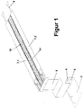
- FIG. 1 shows the structure of a system carrier 1 designed as a sheet metal molded part. This consists of a system anchor 2, a joint part 4 and a support 7.
- the system anchor 2 serves to fix the system carrier 1 on the rafters 14 (See Figures 2 to 5) and has holes 3 for the roof nails Mistake.
- the system carrier 1 is a joint part 4 at right angles to the system anchor 2 formed that has a trough-shaped shape. To heat transfer too deteriorate, is in the joint part 4, a lower recess 5 and an upper recess 6 provided.
- the system carrier 1 then continues as carrier 7.
- the carrier 7 consists of Parts 7.1 and 7.2 lying side by side symmetrically to the central axis. This Parts 7.1 and 7.2 are connected to one another via webs 11, so that there is a ladder-shaped Appearance.
- the carrier 7 has two symmetrically on the side facing the joint part 4 to the central axis arranged T-shaped recesses 8. On the opposite lying side there are corresponding T-shaped extensions 9.
- the slide piece 19 shown in FIG. 6 is assigned to the system carrier 1. This is mountable on the carrier 7 and displaceable on its longitudinal axis. It will held by the tabs 20. In the middle of the sliding piece 19 there are fixing plates 21 punched out in such a way that the punched out material of the fixing plates 21 from the material plane lifted upwards and the head part 22 pointing towards the ridge is kinked down. This fixer plates 21 are so wide that their kinked Head parts 22 can reach into the empty spaces 23 between the webs 11 of the carrier 7.
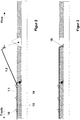
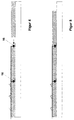
- FIGS. 2 to 5 The assembly of the roof structure according to the invention can be seen from FIGS. 2 to 5.
- the roofing takes place from the eaves to the ridge.
- the first insulation board 13.1 is placed and with the aid of the system carrier 1.1 with the sliding piece 19 attached fixed to the rafters 14 by nailing the system anchor 2 onto the rafters 14 becomes.
- the insulation panels 13 have both the ridge side and the eaves side Edges of grooves 17. Since the groove-shaped shape of the joint part 4 of the system carrier 1 corresponds exactly to the dimensions of the grooves 17, but in the direction of the insulation plate 13 shows away, there is a free space 18 into which a double spring 16th is inserted.
- the sliding piece 19 is fixed in the correct position, that is, the distance between the sliding pieces 19 must be the distance between the slat head rails correspond. This is done by positioning the sliding piece 19 and the fixing plate 21 is knocked down so that its head 22 in the empty spaces 23 of the carrier 7 can grip.
- the slatted head rails can now be suspended in the holding tabs 24.
Landscapes
- Engineering & Computer Science (AREA)
- Architecture (AREA)
- Civil Engineering (AREA)
- Structural Engineering (AREA)
- Roof Covering Using Slabs Or Stiff Sheets (AREA)
- Connection Of Plates (AREA)
Applications Claiming Priority (2)
| Application Number | Priority Date | Filing Date | Title |
|---|---|---|---|
| DE19753940 | 1997-12-05 | ||
| DE1997153940 DE19753940A1 (de) | 1997-12-05 | 1997-12-05 | Variable Unterdachkonstruktion für Steildächer |
Publications (2)
| Publication Number | Publication Date |
|---|---|
| EP0921246A2 true EP0921246A2 (fr) | 1999-06-09 |
| EP0921246A3 EP0921246A3 (fr) | 2000-11-15 |
Family
ID=7850819
Family Applications (1)
| Application Number | Title | Priority Date | Filing Date |
|---|---|---|---|
| EP98122672A Withdrawn EP0921246A3 (fr) | 1997-12-05 | 1998-11-30 | Construction de sous-toiture variable pour toit à forte pente |
Country Status (2)
| Country | Link |
|---|---|
| EP (1) | EP0921246A3 (fr) |
| DE (1) | DE19753940A1 (fr) |
Family Cites Families (6)
| Publication number | Priority date | Publication date | Assignee | Title |
|---|---|---|---|---|
| DE3132152A1 (de) * | 1980-11-10 | 1982-06-24 | Sicroman S.A., 3960 Sierre | Daemmverbundschicht fuer steildaecher |
| DE3318608A1 (de) * | 1982-12-08 | 1984-06-14 | Trube & Kings KG, 5000 Köln | Waermedaemmsystem fuer daecher |
| FR2558196A2 (fr) * | 1983-01-24 | 1985-07-19 | Attali Freddy | Dispositif de fixation reglable de liteaux sur une structure |
| DE3327183A1 (de) * | 1983-03-16 | 1984-09-20 | Dlw Ag, 7120 Bietigheim-Bissingen | Vorrichtung zum befestigen von daemmplatten auf dachsparren |
| DE3441093A1 (de) * | 1984-11-09 | 1986-05-22 | Helfrecht, Manfred, 8598 Waldershof | Waermedaemmendes unterdach |
| DE4338503A1 (de) * | 1993-11-11 | 1995-05-18 | Andreas Decker | Unterdachkonstruktion |
-
1997
- 1997-12-05 DE DE1997153940 patent/DE19753940A1/de not_active Withdrawn
-
1998
- 1998-11-30 EP EP98122672A patent/EP0921246A3/fr not_active Withdrawn
Also Published As
| Publication number | Publication date |
|---|---|
| DE19753940A1 (de) | 1999-06-10 |
| EP0921246A3 (fr) | 2000-11-15 |
Similar Documents
| Publication | Publication Date | Title |
|---|---|---|
| DE69415093T2 (de) | Flächige Dacheindeckung aus gefaltenen Metallblechen | |
| DE19510094A1 (de) | Blechdachsystem | |
| EP1845319A2 (fr) | Dispositif de fixation pour le montage sur le toit d'un élément d'accessoire de toit pouvant être monté sur un toit incliné | |
| DE3214890C2 (fr) | ||
| EP0890005B1 (fr) | Element de support pour fixer un element de construction plat en forme de panneau sur un toit en pente | |
| EP0653528B1 (fr) | Construction de sous-toiture | |
| DE3327183C2 (fr) | ||
| DE3046380C2 (de) | Wärmesammlerelement für ein Energiedach oder eine Energiefassade | |
| DE3933108C2 (fr) | ||
| EP3936680B1 (fr) | Revêtement de façade ou de toiture comportant des éléments de revêtement | |
| EP2505936A1 (fr) | Dispositif de fixation pour un profil de support | |
| DE3513404A1 (de) | Distanz- und belueftungselement fuer zweischalige dachkonstruktionen | |
| DE7708919U1 (de) | Dachbelagbahn | |
| EP0921246A2 (fr) | Construction de sous-toiture variable pour toit à forte pente | |
| EP0921247A2 (fr) | Construction de sous-toiture pour toit à forte pente | |
| DE29501224U1 (de) | Unterkonstruktion für mit Dachplatten eingedeckte Steildächer | |
| DE3941216A1 (de) | Firstziegelhalterung | |
| DE60200924T2 (de) | Montageanordnung für auf einem First montiertes Solarheizelement | |
| DE4131460C2 (de) | Randeinfassung für ein Flachdach oder einen Balkon | |
| CH644924A5 (de) | Dacheindeckungsplatte mit waermeleitvorrichtung. | |
| DE19753939A1 (de) | Unterdacheinhängung für Steildächer | |
| DE3333937C2 (fr) | ||
| DE3018398A1 (de) | Fassadenbekleidung | |
| DE3404814C2 (fr) | ||
| EP3680414B1 (fr) | Assemblage avec un élément de couverture de toit et deux éléments de fixation séparés |
Legal Events
| Date | Code | Title | Description |
|---|---|---|---|
| PUAI | Public reference made under article 153(3) epc to a published international application that has entered the european phase |
Free format text: ORIGINAL CODE: 0009012 |
|
| AK | Designated contracting states |
Kind code of ref document: A2 Designated state(s): AT CH DE DK FR GB LI SE |
|
| AX | Request for extension of the european patent |
Free format text: AL;LT;LV;MK;RO;SI |
|
| PUAL | Search report despatched |
Free format text: ORIGINAL CODE: 0009013 |
|
| RIC1 | Information provided on ipc code assigned before grant |
Free format text: 7E 04B 7/20 A, 7E 04D 12/00 B |
|
| AK | Designated contracting states |
Kind code of ref document: A3 Designated state(s): AT BE CH CY DE DK ES FI FR GB GR IE IT LI LU MC NL PT SE |
|
| AX | Request for extension of the european patent |
Free format text: AL;LT;LV;MK;RO;SI |
|
| AKX | Designation fees paid |
Free format text: AT CH DE DK FR GB LI SE |
|
| STAA | Information on the status of an ep patent application or granted ep patent |
Free format text: STATUS: THE APPLICATION IS DEEMED TO BE WITHDRAWN |
|
| 18D | Application deemed to be withdrawn |
Effective date: 20010601 |