EP0921315A2 - Mécanisme de refoulement à soupape pour un compresseur - Google Patents
Mécanisme de refoulement à soupape pour un compresseur Download PDFInfo
- Publication number
- EP0921315A2 EP0921315A2 EP98630063A EP98630063A EP0921315A2 EP 0921315 A2 EP0921315 A2 EP 0921315A2 EP 98630063 A EP98630063 A EP 98630063A EP 98630063 A EP98630063 A EP 98630063A EP 0921315 A2 EP0921315 A2 EP 0921315A2
- Authority
- EP
- European Patent Office
- Prior art keywords
- discharge port
- valve
- notch
- discharge
- flow
- Prior art date
- Legal status (The legal status is an assumption and is not a legal conclusion. Google has not performed a legal analysis and makes no representation as to the accuracy of the status listed.)
- Withdrawn
Links
- 239000012530 fluid Substances 0.000 claims description 3
- 230000009471 action Effects 0.000 claims description 2
- 238000004891 communication Methods 0.000 claims description 2
- 238000009499 grossing Methods 0.000 abstract 1
- 238000007906 compression Methods 0.000 description 11
- 230000006835 compression Effects 0.000 description 10
- 238000005096 rolling process Methods 0.000 description 4
- 230000007704 transition Effects 0.000 description 2
- 230000008859 change Effects 0.000 description 1
- 230000001419 dependent effect Effects 0.000 description 1
- 239000000463 material Substances 0.000 description 1
- 238000012986 modification Methods 0.000 description 1
- 230000004048 modification Effects 0.000 description 1
- 230000010349 pulsation Effects 0.000 description 1
- 238000005086 pumping Methods 0.000 description 1
- 230000009467 reduction Effects 0.000 description 1
- 238000005057 refrigeration Methods 0.000 description 1
- 238000003466 welding Methods 0.000 description 1
Images




Classifications
-
- F—MECHANICAL ENGINEERING; LIGHTING; HEATING; WEAPONS; BLASTING
- F04—POSITIVE - DISPLACEMENT MACHINES FOR LIQUIDS; PUMPS FOR LIQUIDS OR ELASTIC FLUIDS
- F04C—ROTARY-PISTON, OR OSCILLATING-PISTON, POSITIVE-DISPLACEMENT MACHINES FOR LIQUIDS; ROTARY-PISTON, OR OSCILLATING-PISTON, POSITIVE-DISPLACEMENT PUMPS
- F04C18/00—Rotary-piston pumps specially adapted for elastic fluids
- F04C18/30—Rotary-piston pumps specially adapted for elastic fluids having the characteristics covered by two or more of groups F04C18/02, F04C18/08, F04C18/22, F04C18/24, F04C18/48, or having the characteristics covered by one of these groups together with some other type of movement between co-operating members
- F04C18/34—Rotary-piston pumps specially adapted for elastic fluids having the characteristics covered by two or more of groups F04C18/02, F04C18/08, F04C18/22, F04C18/24, F04C18/48, or having the characteristics covered by one of these groups together with some other type of movement between co-operating members having the movement defined in group F04C18/08 or F04C18/22 and relative reciprocation between the co-operating members
- F04C18/356—Rotary-piston pumps specially adapted for elastic fluids having the characteristics covered by two or more of groups F04C18/02, F04C18/08, F04C18/22, F04C18/24, F04C18/48, or having the characteristics covered by one of these groups together with some other type of movement between co-operating members having the movement defined in group F04C18/08 or F04C18/22 and relative reciprocation between the co-operating members with vanes reciprocating with respect to the outer member
-
- F—MECHANICAL ENGINEERING; LIGHTING; HEATING; WEAPONS; BLASTING
- F04—POSITIVE - DISPLACEMENT MACHINES FOR LIQUIDS; PUMPS FOR LIQUIDS OR ELASTIC FLUIDS
- F04C—ROTARY-PISTON, OR OSCILLATING-PISTON, POSITIVE-DISPLACEMENT MACHINES FOR LIQUIDS; ROTARY-PISTON, OR OSCILLATING-PISTON, POSITIVE-DISPLACEMENT PUMPS
- F04C29/00—Component parts, details or accessories of pumps or pumping installations, not provided for in groups F04C18/00 - F04C28/00
- F04C29/12—Arrangements for admission or discharge of the working fluid, e.g. constructional features of the inlet or outlet
- F04C29/124—Arrangements for admission or discharge of the working fluid, e.g. constructional features of the inlet or outlet with inlet and outlet valves specially adapted for rotary or oscillating piston pumps
- F04C29/126—Arrangements for admission or discharge of the working fluid, e.g. constructional features of the inlet or outlet with inlet and outlet valves specially adapted for rotary or oscillating piston pumps of the non-return type
- F04C29/128—Arrangements for admission or discharge of the working fluid, e.g. constructional features of the inlet or outlet with inlet and outlet valves specially adapted for rotary or oscillating piston pumps of the non-return type of the elastic type, e.g. reed valves
-
- F—MECHANICAL ENGINEERING; LIGHTING; HEATING; WEAPONS; BLASTING
- F04—POSITIVE - DISPLACEMENT MACHINES FOR LIQUIDS; PUMPS FOR LIQUIDS OR ELASTIC FLUIDS
- F04B—POSITIVE-DISPLACEMENT MACHINES FOR LIQUIDS; PUMPS
- F04B39/00—Component parts, details, or accessories, of pumps or pumping systems specially adapted for elastic fluids, not otherwise provided for in, or of interest apart from, groups F04B25/00 - F04B37/00
- F04B39/0027—Pulsation and noise damping means
-
- F—MECHANICAL ENGINEERING; LIGHTING; HEATING; WEAPONS; BLASTING
- F04—POSITIVE - DISPLACEMENT MACHINES FOR LIQUIDS; PUMPS FOR LIQUIDS OR ELASTIC FLUIDS
- F04C—ROTARY-PISTON, OR OSCILLATING-PISTON, POSITIVE-DISPLACEMENT MACHINES FOR LIQUIDS; ROTARY-PISTON, OR OSCILLATING-PISTON, POSITIVE-DISPLACEMENT PUMPS
- F04C29/00—Component parts, details or accessories of pumps or pumping installations, not provided for in groups F04C18/00 - F04C28/00
- F04C29/06—Silencing
- F04C29/068—Silencing the silencing means being arranged inside the pump housing
-
- F—MECHANICAL ENGINEERING; LIGHTING; HEATING; WEAPONS; BLASTING
- F04—POSITIVE - DISPLACEMENT MACHINES FOR LIQUIDS; PUMPS FOR LIQUIDS OR ELASTIC FLUIDS
- F04C—ROTARY-PISTON, OR OSCILLATING-PISTON, POSITIVE-DISPLACEMENT MACHINES FOR LIQUIDS; ROTARY-PISTON, OR OSCILLATING-PISTON, POSITIVE-DISPLACEMENT PUMPS
- F04C29/00—Component parts, details or accessories of pumps or pumping installations, not provided for in groups F04C18/00 - F04C28/00
- F04C29/12—Arrangements for admission or discharge of the working fluid, e.g. constructional features of the inlet or outlet
- F04C29/124—Arrangements for admission or discharge of the working fluid, e.g. constructional features of the inlet or outlet with inlet and outlet valves specially adapted for rotary or oscillating piston pumps
Definitions
- the discharge port is in the motor end bearing.
- the discharge port is located such that about half of it overlies the piston bore and the remainder overlies the cylinder.
- the portion of the cylinder overlain by the discharge port is recessed to provide a fluid path from the cylinder bore to the discharge port. Accordingly, the discharge port faces the piston bore and recess.
- the entrance to the discharge port is normally chamfered.
- the discharge port is exposed to the compression chamber during the entire compression and discharge cycles. However, flow, other than that associated with the reduction in volume during the compression cycle, does not take place until the pressure in the compression chamber is sufficient to open the discharge valve against any bias and system pressure acting on the discharge valve and tending to keep it closed. It follows that there is normally a significant registration between the compression chamber and the discharge port at the time of opening of the discharge valve.
- a notch is provided in the motor end bearing at the entrance to the discharge port.
- the notch is aligned with the direction of the discharge valve centerline and is located on the side of the discharge port corresponding to the pivoted end of the discharge valve. Accordingly, the notch provides a smooth transition for flow from the compression chamber to the discharge port. Additionally, the notch tends to direct the flow towards the free end of the valve, thereby providing a less circuitous path. Since the notch is localized, it does not unnecessarily add to the clearance volume.
- a notch is provided in a portion of the motor end bearing at the entrance to the discharge port such that flow is directed through the discharge port in a streamlined manner and towards the free end of the discharge valve.
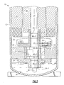
- the numeral 10 generally designates a vertical, high side rolling piston compressor.
- the numeral 12 generally designates the shell or casing.
- Suction tube 16 is sealed to shell 12 and provides fluid communication between suction accumulator 14, which is connected to the evaporator (not illustrated), and suction chamber S.
- Suction chamber S is defined by bore 20-1 in cylinder 20, piston 22, pump end bearing 24 and motor end bearing 28.
- Eccentric shaft 40 includes a portion 40-1 supportingly received in bore 24-1 of pump end bearing 24, eccentric 40-2 which is received in bore 22-1 of piston 22, and portion 40-3 supportingly received in bore 28-1 of motor end bearing 28.
- Oil pick up tube 34 extends into sump 36 from a bore in portion 40-1.
- Stator 42 is secured to shell 12 by shrink fit, welding or any other suitable means.
- Rotor 44 is suitably secured to shaft 40, as by a shrink fit, and is located within bore 42-1 of stator 42 and coacts therewith to define an electric motor.
- Vane 30 is biased into contact with piston 22 by spring 31.
- discharge port 28-2 is formed in motor end bearing 28 and partially overlies bore 20-1 and overlies discharge recess 20-3 which is best shown in Figure 2 and which provides a flow path from compression chamber C to discharge port 28-2.
- Discharge port 28-2 is serially overlain by discharge valve 38 and spaced valve stop 39, as is conventional.
- compressor 10 is generally conventional.
- the present invention adds notch 28-3A which is best shown in Figures 3-6. In Figure 3 the view of notch 28-3A is that seen when looking in the direction of the axis of valve 28 towards the fixed end of valve 28.
- Notch 28-3A is a more extensively recessed portion of chamfer 28-3, as best shown in Figure 4A, and has a projected profile that has a curved shape that intersects with the discharge port 28-2 or, preferably, with the discharge port chamfer 28-3.
- Notch 28-3A is symmetrical with the axis of the discharge valve 38.
- Notch 28-3 can be 10° to 180° in circumferential extent. but is preferably 90° or less, and corresponds. in part, to a portion of discharge port 28-2 overlying bore 20-1, or, more specifically, compression chamber C.
- the notch 28-3A mostly overlies cylinder 20 but because of its limited circumferential extent it does not significantly add to the clearance volume. Notch 28-3A is located, however, where at least some of the flow from compression chamber C to discharge port 28-2 would otherwise be over a 90° edge with attendant losses.
- the valve 38 is flexed on opening and has its greatest distance from valve seat 28-4 and hence the least resistance to flow on the side of discharge port 28-2 opposite to notch 28-3A.
- notch 28-3A tends to be diverted to a limited degree such that the flow tends to go diagonally across port 28-2 with only a glancing impingement on valve 38 and passing past the tip of valve 38.
- rotor 44 and eccentric shaft 40 rotate as a unit and eccentric 40-2 causes movement of piston 22.
- Oil from sump 36 is drawn through oil pick up tube 34 into bore 40-4 which acts as a centrifugal pump. The pumping action will be dependent upon the rotational speed of shaft 40.
- Oil delivered to bore 40-4 is able to flow into a series of radially extending passages, in portion 40-1, eccentric 40-2 and portion 40-3 to lubricate bearing 24, piston 22, and bearing 28, respectively.
- Piston 22 coacts with vane 30 in a conventional manner such that gas is drawn through suction tube 16 and passageway 20-2 to suction chamber S.
- the gas in suction chamber S is trapped, compressed and discharged from ccmpression chamber C via a flow path defined by notch 28-3A and recess 20-3 into discharge port 28-2.
- the high pressure gas unseats the valve 38 and passes into the interior of muffler 32.
- the compressed gas passes through muffler 32 into the interior of shell 12 and passes via the annular gap between rotating rotor 44 and stator 42 and through discharge line 60 to the condenser 70 of a refrigeration circuit (not illustrated).
- the direction of motion of piston 22 will be tangent to the bore 20-1, in the region of recess 20-3 or, nominally, as shown in Figure 5.
- the clearance volume will be the volume of recess 20-3, the volume of discharge port 28-2, the volume of chamfer 28-3, and the volume of the material removed to form notch 28-3A. Accordingly, the increase in the clearance volume is minimized due to the reduced circumferential extent of notch 28-3A.
- Port 128-2 differs from port 28-2 by the addition of a second flow guiding surface 128-3B located across port 128-2 from notch 128-3A. Notch 128-3A and guiding surface 128-3B coact to provide a streamlined flow and to guide the flow in a direction along the axis of valve 138 such that the flow tends to glance off valve 138 and flow past the tip of valve 138.
- Discharge port 228-2 is circular but formed at an angle in motor end bearing 228 such that flow through port 228-2 is directed towards the free end of valve 238.
- the angle of port 228-2 effectively forms an inlet notch and a discharge notch when port 228-2 is viewed straight on.
Landscapes
- Engineering & Computer Science (AREA)
- Mechanical Engineering (AREA)
- General Engineering & Computer Science (AREA)
- Applications Or Details Of Rotary Compressors (AREA)
- Compressor (AREA)
- Rotary Pumps (AREA)
Applications Claiming Priority (2)
| Application Number | Priority Date | Filing Date | Title |
|---|---|---|---|
| US08/986,451 US6042351A (en) | 1997-12-08 | 1997-12-08 | Enhanced flow compressor discharge port entrance |
| US986451 | 1997-12-08 |
Publications (2)
| Publication Number | Publication Date |
|---|---|
| EP0921315A2 true EP0921315A2 (fr) | 1999-06-09 |
| EP0921315A3 EP0921315A3 (fr) | 2000-05-03 |
Family
ID=25532433
Family Applications (1)
| Application Number | Title | Priority Date | Filing Date |
|---|---|---|---|
| EP98630063A Withdrawn EP0921315A3 (fr) | 1997-12-08 | 1998-10-30 | Mécanisme de refoulement à soupape pour un compresseur |
Country Status (7)
| Country | Link |
|---|---|
| US (1) | US6042351A (fr) |
| EP (1) | EP0921315A3 (fr) |
| JP (1) | JP3057064B2 (fr) |
| KR (1) | KR100308860B1 (fr) |
| CN (1) | CN1219649A (fr) |
| BR (1) | BR9805209A (fr) |
| TW (1) | TW426787B (fr) |
Families Citing this family (9)
| Publication number | Priority date | Publication date | Assignee | Title |
|---|---|---|---|---|
| JP4291436B2 (ja) * | 1998-09-10 | 2009-07-08 | 東芝キヤリア株式会社 | 冷凍サイクル用圧縮機 |
| DE10360709A1 (de) * | 2003-12-19 | 2005-10-06 | Bartels Mikrotechnik Gmbh | Mikropumpe und klebstoffreies Verfahren zur Verbindung zweier Substrate |
| JP2008175188A (ja) | 2007-01-22 | 2008-07-31 | Toshiba Carrier Corp | 回転式圧縮機、冷凍サイクル装置 |
| JP4974974B2 (ja) * | 2008-07-09 | 2012-07-11 | 三菱電機株式会社 | 密閉型回転圧縮機 |
| CN101660533A (zh) * | 2008-08-29 | 2010-03-03 | 上海日立电器有限公司 | 排气座圈 |
| JP6070069B2 (ja) * | 2012-10-30 | 2017-02-01 | 株式会社富士通ゼネラル | ロータリ圧縮機 |
| CN103452854B (zh) * | 2013-08-19 | 2016-06-29 | 广东美芝制冷设备有限公司 | 旋转式压缩机 |
| CN104564690B (zh) * | 2015-01-08 | 2016-11-16 | 广东美芝制冷设备有限公司 | 压缩机构和具有其的压缩机 |
| CN113931846A (zh) * | 2021-11-19 | 2022-01-14 | 浙江百达精工股份有限公司 | 一种旋转式压缩机冷媒排出结构 |
Family Cites Families (11)
| Publication number | Priority date | Publication date | Assignee | Title |
|---|---|---|---|---|
| US2154880A (en) * | 1935-12-24 | 1939-04-18 | Landers Frary & Clark | Valve |
| GB1140452A (en) * | 1966-03-16 | 1969-01-22 | Edwards High Vacuum Int Ltd | Improvements relating to liquid sealed mechanical vacuum pumps |
| JPS6165970A (ja) * | 1984-09-07 | 1986-04-04 | Matsushita Electric Ind Co Ltd | 密閉型圧縮機 |
| JPS6179889A (ja) * | 1984-09-26 | 1986-04-23 | Matsushita Electric Ind Co Ltd | 密閉形回転式電動圧縮機の吐出口装置 |
| JPS61182485A (ja) * | 1985-02-07 | 1986-08-15 | Matsushita Electric Ind Co Ltd | 回転式密閉型圧縮機 |
| JPH01232195A (ja) * | 1988-03-11 | 1989-09-18 | Matsushita Refrig Co Ltd | 回転型圧縮機の吸入装置 |
| BR8802894A (pt) * | 1988-06-09 | 1990-01-23 | Brasil Compressores Sa | Compressor rotativo de pistao rolante |
| JP3350276B2 (ja) * | 1994-12-28 | 2002-11-25 | 東芝キヤリア株式会社 | ロータリコンプレッサ |
| JP2630289B2 (ja) * | 1995-01-23 | 1997-07-16 | 日本電気株式会社 | センス増幅器 |
| KR970027870A (ko) * | 1995-11-04 | 1997-06-24 | 윌리엄 더블류. 하벨트 | 단단한 수용체에 박기 위한 고정 요소 |
| US5775894A (en) * | 1996-11-05 | 1998-07-07 | Tecumseh Products Company | Compressor ball valve |
-
1997
- 1997-12-08 US US08/986,451 patent/US6042351A/en not_active Expired - Fee Related
-
1998
- 1998-10-28 TW TW087117886A patent/TW426787B/zh not_active IP Right Cessation
- 1998-10-30 EP EP98630063A patent/EP0921315A3/fr not_active Withdrawn
- 1998-11-10 JP JP10318500A patent/JP3057064B2/ja not_active Expired - Fee Related
- 1998-12-07 BR BR9805209-8A patent/BR9805209A/pt not_active IP Right Cessation
- 1998-12-07 CN CN98123283A patent/CN1219649A/zh active Pending
- 1998-12-08 KR KR1019980053694A patent/KR100308860B1/ko not_active Expired - Fee Related
Non-Patent Citations (1)
| Title |
|---|
| None |
Also Published As
| Publication number | Publication date |
|---|---|
| JP3057064B2 (ja) | 2000-06-26 |
| JPH11218081A (ja) | 1999-08-10 |
| BR9805209A (pt) | 1999-11-23 |
| US6042351A (en) | 2000-03-28 |
| CN1219649A (zh) | 1999-06-16 |
| KR19990066835A (ko) | 1999-08-16 |
| KR100308860B1 (ko) | 2001-12-17 |
| EP0921315A3 (fr) | 2000-05-03 |
| TW426787B (en) | 2001-03-21 |
Similar Documents
| Publication | Publication Date | Title |
|---|---|---|
| US7431571B2 (en) | Noise reduction muffler for hermetic rotary compressor | |
| US5605447A (en) | Noise reduction in a hermetic rotary compressor | |
| EP0622546B1 (fr) | Compresseur à piston rotatif avec injection d'huile | |
| US5676535A (en) | Enhanced rotary compressor valve port entrance | |
| US6042351A (en) | Enhanced flow compressor discharge port entrance | |
| CN100507276C (zh) | 压缩机 | |
| CN101072945B (zh) | 压缩机 | |
| CA2080577C (fr) | Compresseur rotatif a palettes a pression reduite sur les pointes interieures des palettes | |
| JPH04228894A (ja) | 回転式圧縮機 | |
| JPH04255591A (ja) | 回転式圧縮機 | |
| KR102663577B1 (ko) | 전동압축기 | |
| JP3861633B2 (ja) | 密閉型圧縮機 | |
| JP2602653Y2 (ja) | 気体圧縮機 | |
| JPH09222088A (ja) | 縦形ロータリ圧縮機 | |
| KR100425741B1 (ko) | 압축기의 냉매 유동손실 저감구조 | |
| KR200148584Y1 (ko) | 밀폐형 회전식 압축기의 토출장치 | |
| JPH10252676A (ja) | 気体圧縮機用シリンダおよび気体圧縮機 | |
| KR100273428B1 (ko) | 밀폐형 회전식 압축기의 토출소음 저감구조 | |
| JP4171252B2 (ja) | 気体圧縮機 | |
| JP3236366B2 (ja) | 回転式圧縮機 | |
| JPH1018984A (ja) | ロータリコンプレッサ | |
| KR20210074778A (ko) | 압축기 | |
| JPH03189395A (ja) | ロータリ圧縮機 | |
| JP2005002902A (ja) | 気体圧縮機 | |
| JPH08135584A (ja) | 縦型ロータリ圧縮機 |
Legal Events
| Date | Code | Title | Description |
|---|---|---|---|
| PUAI | Public reference made under article 153(3) epc to a published international application that has entered the european phase |
Free format text: ORIGINAL CODE: 0009012 |
|
| AK | Designated contracting states |
Kind code of ref document: A2 Designated state(s): ES FR IT |
|
| AX | Request for extension of the european patent |
Free format text: AL;LT;LV;MK;RO;SI |
|
| 17P | Request for examination filed |
Effective date: 19991112 |
|
| PUAL | Search report despatched |
Free format text: ORIGINAL CODE: 0009013 |
|
| AK | Designated contracting states |
Kind code of ref document: A3 Designated state(s): AT BE CH CY DE DK ES FI FR GB GR IE IT LI LU MC NL PT SE |
|
| AX | Request for extension of the european patent |
Free format text: AL;LT;LV;MK;RO;SI |
|
| AKX | Designation fees paid |
Free format text: ES FR IT |
|
| REG | Reference to a national code |
Ref country code: DE Ref legal event code: 8566 |
|
| 17Q | First examination report despatched |
Effective date: 20030417 |
|
| STAA | Information on the status of an ep patent application or granted ep patent |
Free format text: STATUS: THE APPLICATION IS DEEMED TO BE WITHDRAWN |
|
| 18D | Application deemed to be withdrawn |
Effective date: 20030828 |