EP0921340A2 - Valve for fluid conveyance system - Google Patents
Valve for fluid conveyance system Download PDFInfo
- Publication number
- EP0921340A2 EP0921340A2 EP98122698A EP98122698A EP0921340A2 EP 0921340 A2 EP0921340 A2 EP 0921340A2 EP 98122698 A EP98122698 A EP 98122698A EP 98122698 A EP98122698 A EP 98122698A EP 0921340 A2 EP0921340 A2 EP 0921340A2
- Authority
- EP
- European Patent Office
- Prior art keywords
- tang
- nut
- valve
- throat
- valve according
- Prior art date
- Legal status (The legal status is an assumption and is not a legal conclusion. Google has not performed a legal analysis and makes no representation as to the accuracy of the status listed.)
- Withdrawn
Links
- 239000012530 fluid Substances 0.000 title claims abstract description 19
- 230000004323 axial length Effects 0.000 claims description 4
- 229910000906 Bronze Inorganic materials 0.000 claims description 2
- 239000010974 bronze Substances 0.000 claims description 2
- KUNSUQLRTQLHQQ-UHFFFAOYSA-N copper tin Chemical compound [Cu].[Sn] KUNSUQLRTQLHQQ-UHFFFAOYSA-N 0.000 claims description 2
- BHEPBYXIRTUNPN-UHFFFAOYSA-N hydridophosphorus(.) (triplet) Chemical compound [PH] BHEPBYXIRTUNPN-UHFFFAOYSA-N 0.000 claims description 2
- 238000009434 installation Methods 0.000 description 3
- 230000015556 catabolic process Effects 0.000 description 2
- 230000008878 coupling Effects 0.000 description 2
- 238000010168 coupling process Methods 0.000 description 2
- 238000005859 coupling reaction Methods 0.000 description 2
- 239000013013 elastic material Substances 0.000 description 2
- 238000007789 sealing Methods 0.000 description 2
- 230000000295 complement effect Effects 0.000 description 1
- 239000007788 liquid Substances 0.000 description 1
- 239000000463 material Substances 0.000 description 1
- 239000002184 metal Substances 0.000 description 1
- 229910052751 metal Inorganic materials 0.000 description 1
- 150000002739 metals Chemical class 0.000 description 1
Images

Classifications
-
- F—MECHANICAL ENGINEERING; LIGHTING; HEATING; WEAPONS; BLASTING
- F16—ENGINEERING ELEMENTS AND UNITS; GENERAL MEASURES FOR PRODUCING AND MAINTAINING EFFECTIVE FUNCTIONING OF MACHINES OR INSTALLATIONS; THERMAL INSULATION IN GENERAL
- F16L—PIPES; JOINTS OR FITTINGS FOR PIPES; SUPPORTS FOR PIPES, CABLES OR PROTECTIVE TUBING; MEANS FOR THERMAL INSULATION IN GENERAL
- F16L19/00—Joints in which sealing surfaces are pressed together by means of a member, e.g. a swivel nut, screwed on, or into, one of the joint parts
- F16L19/02—Pipe ends provided with collars or flanges, integral with the pipe or not, pressed together by a screwed member
- F16L19/0231—Pipe ends provided with collars or flanges, integral with the pipe or not, pressed together by a screwed member with specially adapted means for positioning the threaded member behind the collar
Definitions
- the present invention relates to a valve for fluid conveyance systems. More particularly, the present invention relates to a valve for fluid conveyance systems suitable to be easily disengaged from the related system should its replacement become necessary.
- the valve of the present invention is particularly suitable for use in all those systems wherein a fluid runs and it is necessary to intercept said fluid to block or deviate its flow, and wherein said valve is subjected to be replaced.
- the valve of the present invention in fact, may be replaced, for instance, as a consequence of a working failure of the same valve, or a breakdown of the same, in a simple and quick manner, on prior emptying of the liquid which runs in the system.
- valves for fluid conveyance systems, for instance ball-valve, fitted-in valves, gate valves, etc.
- Said conventional valves generally have as a connection type, a female (or male (threading), obtained on both ends of the valve body, which threading engages with like male (or female) threadings obtained at the ends of ducts or pipings which connect with said valves.
- Object of this invention is to obviate the aforementioned drawbacks.
- object of this invention is to realise a valve for fluid conveyance systems such as to be easily and quickly assembled in the system and as easily eliminated and replaced in case of a failure or breakdown of the same.
- Another object of this invention is to allow the easy replacement of the valve, if this should be installed in obliged and difficult access positions, wherein one has to work in small spaces.
- Another object of the present invention is to provide a valve that can make up, at least to some extent, for the possible distance errors between the pipings wherein it is inserted.
- a further object of the present invention is to provide a valve that can reduce possible leakage points, utilising simple and reliable seal elements, and that has a high degree of resistance and reliability in the time, and that is such as to be easily and economically realised.
- valve for fluid conveyance systems comprising:
- the slide-chamber is provided with at least a throat wherein an elastic ring is inserted, wherein the internal surface of the nut or sleeve is provided with at least a throat that contains an elastic ring, and the tang has an external diameter that increases stepwise towards the end facing the piping and comprises at least a step connected by a bevelling or tapering, said elastic ring striling against said bevelling or tapering.
- the tang may be fixed or freely sliding with respect to the tang when said tang is fixed or sliding, or said nut may be fixed with respect to said tang when the latter is a sliding tang.
- the tang When the tang is a sliding tang, it slides in a chember which the valve body os provided with.
- the portion of tang that slides in said chamber has a diemater that increases stepwise in the direction of the valve body and is provided with at least a throat wherein an O-ring gasket is inserted that has an external diameter greater than the internal diameter of said chamber.
- the slide-chamber is provided with at least a throat, wherein an elastic ring is inserted.
- valve for fluid conveyance systems of the present invention indicated by 1 as a whole, comprises a valve body 1' and, in at least one of its ends, a tang 2 coupled to said valve body 1' and a nut 3 engaged externally on said tang 2.
- Said tang 2 may be fixed or mobile with respect to the valve body 1', and said threaded nut 3 may be fixed on tang 2 when said tang is mobile or may freely slide and rotate on tang 2 when said tang is fixed or mobile.
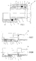
- Figure 1 shows a valve for fluid conveyance systems of the present invention, wherein the connection system is by a fixed tang 2 and nut 3 mobile and free to slide and rotate on said fixed tang 2.
- tang 2 On each of the two ends of the valve body 1', there is rigidly fixed tang 2 having a circular section and an external diameter growing stepwise towards the free external end opposite to the threaded one fixed at an end of the valve body 1'. More particularly, said tang 2 is provided with a first external step, wherefrom a longitudinal portion 4 develops, and a second more internal step 5, said steps being connected to each other and tang 2 by means of bevellings or taperings 6.
- Nut 3 comprises an end facing the valve body 1', with the opposite end facing the external free end of tang 2.
- the internal surface of said nut 3 is provided with a partial threading 16 in the portion facing the free end of tang 2 and is smooth, i.e., non-threaded, in the portion facing the valve body 1'.
- Said non threaded portion of the internal surface is provided with at least a first throat 7, having a section, by way of example and preferably, rectangular, suitable to house an O-ring gasket 9, having preferably a circular section, and at least a second throat 8, having a section, by way of example and preferably, rectangular, suitable to house an elastic ring 10 also of a preferably circular section.
- Said O-ring gasket 9 may be from elastic material of the type of nitrilic rubber NBR for running temperatures of up to 110°C and of the type of fluorinated rubber for temperatures of up to 140°C.
- Said elastic ring 10 is preferably made from deformable metals, of the type, for instance of phosphorous bronze; such material, as is known, allows to combine mechanical resistance and smoothness.
- the seal of the connection system is ensured by the O-ring gasket 9 and the elastic ring 10, both of them having internal diameters smaller than the external diameter of the first step 4 and the second step 5 of tang 2 by means of which the steps of said gasket and said elastic material couple in the tightening position to pipings 17, with a possible interposition of a conventional seal ring 18.
- the partly threaded nut 3 has an axial length smaller than that of the respective tang 2, so that when said nut 3 is in a complementary re-entered position on tang 2, the overall dimensions of valve 1 is only determined by the end of both tangs 2.
- the interaxial distance, along the surface of the threaded nut 3, between said first throat 7 and said second throat 8 is smaller than the axial length of the longitudinal portion of said first external step of tang 2.
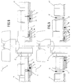
- Figure 2-4 show a variant embodiment of the valve for fluid conveyance systems of the present invention, wherein the connection system has a mobile tang 2 and a nut 3, mobile and free to slide and rotate in said mobile tang 2.
- the coupling of nut 3 and mobile tang 2 is identical to that shown in Figure 1 and previously described.
- the end of each of the two tangs 2, oriented towards the valve body 1', is free to axially slide within a slide-chamber 11 integrally obtained with the same valve body 1'.
- Said end of tang 2 has a diameter that increases stepwise in the direction of the valve body 1', which is structurally equal to that of its other end.
- the portion of said tang which slides within the slide-chamber 11 is provided with at least a throat 12, preferably two throats, wherein an O-ring gasket 13 is included, having for instance a circular section of the previously described type.
- Said O-ring gasket 13 has an external diameter greater than the internal slide-chamber 11; in this way, there is ensured the sealing towards the outside by means of the coupling of tang 2 with the slide-chamber 1.
- said slide-chamber 11 is also provided with at least a throat 14 wherein an elastic ring 15 is inserted of the type previously described and indicated by 10.
- Figures 7 and 8 show a further variant embodiment of the valve for fluid conveyance systems of the present invention, wherein the connection system has a fixed nut 3 and a mobile tang.
- Nut 3 is rigidly connected or is obtained integrally with the end of tang 2, the latter being freely sliding in the inside of a slide-chamber 11 obtained integrally with the valve body 1'.
- the free end of tang 2 has a diameter that increases stepwise in the direction towards the valve body 1' and, in the portion that slides within said slide-chamber 11, said end is provided with at least a throat 12, wherein an O-ring gasket 13 is inserted that has an external diameter greater than the slide-chamber 11, wherein an elastic ring 15 is also inserted.
- connection systems mat anyhow be provided on valves having a threaded end (male or female) or other connection types; the other end may be provided with one of the three types of connection described till now, according to the type of product and the various installation requirements.
- Figures 6 and 7 show a possible combination of the connection systems at the two ends of the valve body 1'; in particular a connection type with fixed tang and mobile nut is used at an end of the valve body 1', and a connection system with a mobile tang and a mobile nut is used at the other end of valve body 1'.
- the working of valve 1 of the present invention in the embodiment shown in Figure 1 is as follows: when nut 3 is screwed on piping 17 of a fluid conveyance system the O-ring gasket 9 remains slightly compressed on the greater diameter of the first step 4 of tang 2 and prevents possible fluid leakages towards the outside and, at the same time, the elastic ring 10 slides in correspondence of the second more internal step 5 of tang 2.
- valve 1 When nut 3 is in this re-entered position, it does not protrude from tang 2 and the overall dimensions of valve 1 are determined by the end of the two tangs 2. This characteristic is very important as it allows to unscrew nuts 3 and to extract valve 1 from pipings 17 without having recourse to extraordinary operation.
- valve connection system may also be mobile.
- tang 2 slides within a chamber 11 integrally obtained with the valve body 1' and in this case the mobile walls become both nut 3 that slides on tang 2 and tang 2 that slides in its turn inside the valve body 1'.
- This telescopic tang variant may be utilised whenever valve 1 must be installed in obliged and difficult-access positions, when one has to work in narrow spaces. This solution allows in fact to handle more easily valve 1 both during the installation and the removal.
- the movement of tang 2 lends valve 1 the characteristic of having variable overall dimensions, and allows therefore to make up, to some extent, for the distance errors between pipings 17.
- Figures 2-4 show respectively the connection system with a mobile tang 2 and a free nut 3, with tang 2 in extension and nut 3 free, and with tang 2 and nut 3 in tightening position on piping 17.
- FIG. 7 and 8 A further variant of the valve of the present invention, shown in Figures 7 and 8, provides a connection system with a mobile tang 2 and nut 3 rigidly connected or integral with the free end of tang 2.
- the tightening of nut 3 on piping 17 causes also tang 2 to rotate in the inside of the slide-chamber 11.
- Figures 7 and 8 shows, sequentially, the connection system with tang 2 mobile and the related nut 3 respectively in a free position and in a tightening position on pipings 17.
- valve for fluid conveyance systems of the present invention in the light of the above teachings.
- slide-chamber 11 it is possible to realise at least a further throat wherein an O-ring gasket is inserted that ensure the seal.
- nut 3 may be provided with an internal continuous threading, without the first throat 7 with the related sealing O-ring gasket 9 being obtained in its inside.
Landscapes
- Engineering & Computer Science (AREA)
- General Engineering & Computer Science (AREA)
- Mechanical Engineering (AREA)
- Magnetically Actuated Valves (AREA)
- Fluid-Driven Valves (AREA)
- Multiple-Way Valves (AREA)
- Quick-Acting Or Multi-Walled Pipe Joints (AREA)
Applications Claiming Priority (2)
| Application Number | Priority Date | Filing Date | Title |
|---|---|---|---|
| IT97MI002712 IT1296847B1 (it) | 1997-12-05 | 1997-12-05 | Valvola per impianti di conduzione fluidi |
| ITMI972712 | 1997-12-05 |
Publications (1)
| Publication Number | Publication Date |
|---|---|
| EP0921340A2 true EP0921340A2 (en) | 1999-06-09 |
Family
ID=11378331
Family Applications (1)
| Application Number | Title | Priority Date | Filing Date |
|---|---|---|---|
| EP98122698A Withdrawn EP0921340A2 (en) | 1997-12-05 | 1998-11-30 | Valve for fluid conveyance system |
Country Status (2)
| Country | Link |
|---|---|
| EP (1) | EP0921340A2 (it) |
| IT (1) | IT1296847B1 (it) |
Cited By (2)
| Publication number | Priority date | Publication date | Assignee | Title |
|---|---|---|---|---|
| EP2128508A3 (en) * | 2008-05-29 | 2012-06-20 | Teco S.r.l. | Fluid shut-off device |
| WO2019029899A1 (en) * | 2017-08-10 | 2019-02-14 | Adey Holdings (2008) Limited | MAGNETIC FILTER FOR CENTRAL HEATING SYSTEM |
-
1997
- 1997-12-05 IT IT97MI002712 patent/IT1296847B1/it active IP Right Grant
-
1998
- 1998-11-30 EP EP98122698A patent/EP0921340A2/en not_active Withdrawn
Non-Patent Citations (1)
| Title |
|---|
| None |
Cited By (5)
| Publication number | Priority date | Publication date | Assignee | Title |
|---|---|---|---|---|
| EP2128508A3 (en) * | 2008-05-29 | 2012-06-20 | Teco S.r.l. | Fluid shut-off device |
| WO2019029899A1 (en) * | 2017-08-10 | 2019-02-14 | Adey Holdings (2008) Limited | MAGNETIC FILTER FOR CENTRAL HEATING SYSTEM |
| CN109381914A (zh) * | 2017-08-10 | 2019-02-26 | 阿迪控股(2008)有限公司 | 中央供热系统的磁性过滤器 |
| CN111201402A (zh) * | 2017-08-10 | 2020-05-26 | 阿迪控股(2008)有限公司 | 中央供热系统的磁过滤器 |
| US11517916B2 (en) | 2017-08-10 | 2022-12-06 | Adey Holdings (2008) Limited | Magnetic filter for a central heating system |
Also Published As
| Publication number | Publication date |
|---|---|
| ITMI972712A1 (it) | 1999-06-05 |
| IT1296847B1 (it) | 1999-08-02 |
Similar Documents
| Publication | Publication Date | Title |
|---|---|---|
| US5538296A (en) | Swivel joint | |
| US6830268B2 (en) | Pipe repair clamp | |
| US3260539A (en) | Coupling for fluid conduits | |
| US6102445A (en) | Sealed coupling system for flexible hose | |
| US2645506A (en) | Pipe flange connection | |
| US4127289A (en) | Coupling for pipelines | |
| US3091483A (en) | Flexible pipe connection having line pressure actuated sealing means | |
| US3423111A (en) | Plain end pipe joint | |
| US4778204A (en) | Pipeline connector for plastic instruments | |
| US3917324A (en) | Pipe joint | |
| US9022431B2 (en) | Pipe fitting | |
| US3223439A (en) | Pipe joint | |
| US6676166B1 (en) | Plastic pipe coupling system | |
| US3776577A (en) | Flow conductor coupling | |
| EP0921340A2 (en) | Valve for fluid conveyance system | |
| RU2564156C2 (ru) | Фиттинг с фланцами для использования с системой герметизации труб | |
| US3357723A (en) | Ball-and-socket pipe joints, and applications thereof | |
| US2452057A (en) | Flexible leakproof coupling | |
| US6488316B1 (en) | Flexible metal hose termination fitting with adapter for termination plate | |
| US3672705A (en) | Pipe jack | |
| US3241867A (en) | Rotatable pipe joint | |
| EP3096059A1 (en) | Rotary coupling | |
| US3610666A (en) | Fluid coupling | |
| US9777874B2 (en) | Rotary coupling | |
| US4909548A (en) | Compound-taper flange assembly |
Legal Events
| Date | Code | Title | Description |
|---|---|---|---|
| PUAI | Public reference made under article 153(3) epc to a published international application that has entered the european phase |
Free format text: ORIGINAL CODE: 0009012 |
|
| AK | Designated contracting states |
Kind code of ref document: A2 Designated state(s): AT BE CH CY DE DK ES FI FR GB GR IE IT LI LU MC NL PT SE |
|
| AX | Request for extension of the european patent |
Free format text: AL;LT;LV;MK;RO;SI |
|
| STAA | Information on the status of an ep patent application or granted ep patent |
Free format text: STATUS: THE APPLICATION IS DEEMED TO BE WITHDRAWN |
|
| 18D | Application deemed to be withdrawn |
Effective date: 20010531 |