EP0921373B1 - Support pour un guide d' ondes mécaniques - Google Patents
Support pour un guide d' ondes mécaniques Download PDFInfo
- Publication number
- EP0921373B1 EP0921373B1 EP98122618A EP98122618A EP0921373B1 EP 0921373 B1 EP0921373 B1 EP 0921373B1 EP 98122618 A EP98122618 A EP 98122618A EP 98122618 A EP98122618 A EP 98122618A EP 0921373 B1 EP0921373 B1 EP 0921373B1
- Authority
- EP
- European Patent Office
- Prior art keywords
- support arrangement
- waveguide
- wave conductor
- conductor
- bearing
- Prior art date
- Legal status (The legal status is an assumption and is not a legal conclusion. Google has not performed a legal analysis and makes no representation as to the accuracy of the status listed.)
- Expired - Lifetime
Links
- 239000004020 conductor Substances 0.000 claims description 75
- 230000000694 effects Effects 0.000 claims description 14
- 238000013016 damping Methods 0.000 claims description 12
- 239000004033 plastic Substances 0.000 claims description 12
- 229920003023 plastic Polymers 0.000 claims description 12
- 239000007787 solid Substances 0.000 claims description 11
- 239000011148 porous material Substances 0.000 claims description 7
- 230000001413 cellular effect Effects 0.000 claims description 5
- 239000000835 fiber Substances 0.000 claims description 5
- 210000003850 cellular structure Anatomy 0.000 claims description 2
- 230000007613 environmental effect Effects 0.000 claims description 2
- 230000001902 propagating effect Effects 0.000 claims 1
- 230000000087 stabilizing effect Effects 0.000 claims 1
- 238000003860 storage Methods 0.000 description 54
- 239000000463 material Substances 0.000 description 27
- 239000007789 gas Substances 0.000 description 10
- 230000006835 compression Effects 0.000 description 9
- 238000007906 compression Methods 0.000 description 9
- 239000011810 insulating material Substances 0.000 description 8
- 239000011888 foil Substances 0.000 description 7
- 238000004519 manufacturing process Methods 0.000 description 7
- 238000005259 measurement Methods 0.000 description 7
- 230000009467 reduction Effects 0.000 description 6
- 230000005284 excitation Effects 0.000 description 5
- 239000011521 glass Substances 0.000 description 5
- -1 keflar Substances 0.000 description 5
- 229920000642 polymer Polymers 0.000 description 5
- 229920002379 silicone rubber Polymers 0.000 description 5
- 239000004945 silicone rubber Substances 0.000 description 5
- 229920001971 elastomer Polymers 0.000 description 4
- 239000000806 elastomer Substances 0.000 description 4
- 239000002657 fibrous material Substances 0.000 description 4
- 238000009413 insulation Methods 0.000 description 4
- 230000035939 shock Effects 0.000 description 4
- 239000004698 Polyethylene Substances 0.000 description 3
- 239000006260 foam Substances 0.000 description 3
- 238000000034 method Methods 0.000 description 3
- 239000004814 polyurethane Substances 0.000 description 3
- IJGRMHOSHXDMSA-UHFFFAOYSA-N Atomic nitrogen Chemical compound N#N IJGRMHOSHXDMSA-UHFFFAOYSA-N 0.000 description 2
- OKTJSMMVPCPJKN-UHFFFAOYSA-N Carbon Chemical compound [C] OKTJSMMVPCPJKN-UHFFFAOYSA-N 0.000 description 2
- 239000004743 Polypropylene Substances 0.000 description 2
- 238000005299 abrasion Methods 0.000 description 2
- 230000009471 action Effects 0.000 description 2
- 239000000853 adhesive Substances 0.000 description 2
- 230000001070 adhesive effect Effects 0.000 description 2
- 229920006231 aramid fiber Polymers 0.000 description 2
- 229910052799 carbon Inorganic materials 0.000 description 2
- 239000002131 composite material Substances 0.000 description 2
- 238000010292 electrical insulation Methods 0.000 description 2
- 239000004744 fabric Substances 0.000 description 2
- 230000002349 favourable effect Effects 0.000 description 2
- 239000003365 glass fiber Substances 0.000 description 2
- 239000012212 insulator Substances 0.000 description 2
- 239000000696 magnetic material Substances 0.000 description 2
- 230000035699 permeability Effects 0.000 description 2
- 229920000573 polyethylene Polymers 0.000 description 2
- 229920001296 polysiloxane Polymers 0.000 description 2
- 229920001343 polytetrafluoroethylene Polymers 0.000 description 2
- 239000004810 polytetrafluoroethylene Substances 0.000 description 2
- 229920000915 polyvinyl chloride Polymers 0.000 description 2
- 239000004800 polyvinyl chloride Substances 0.000 description 2
- 239000000126 substance Substances 0.000 description 2
- YCKRFDGAMUMZLT-UHFFFAOYSA-N Fluorine atom Chemical compound [F] YCKRFDGAMUMZLT-UHFFFAOYSA-N 0.000 description 1
- 239000004952 Polyamide Substances 0.000 description 1
- 229910000831 Steel Inorganic materials 0.000 description 1
- 238000010521 absorption reaction Methods 0.000 description 1
- 239000006098 acoustic absorber Substances 0.000 description 1
- 239000004760 aramid Substances 0.000 description 1
- 230000002238 attenuated effect Effects 0.000 description 1
- 238000001266 bandaging Methods 0.000 description 1
- 239000011324 bead Substances 0.000 description 1
- 230000008901 benefit Effects 0.000 description 1
- 210000004027 cell Anatomy 0.000 description 1
- 229920001577 copolymer Polymers 0.000 description 1
- 238000004132 cross linking Methods 0.000 description 1
- 239000011243 crosslinked material Substances 0.000 description 1
- 230000001419 dependent effect Effects 0.000 description 1
- 239000013013 elastic material Substances 0.000 description 1
- 230000005684 electric field Effects 0.000 description 1
- 230000005672 electromagnetic field Effects 0.000 description 1
- 239000011152 fibreglass Substances 0.000 description 1
- 229910052731 fluorine Inorganic materials 0.000 description 1
- 239000011737 fluorine Substances 0.000 description 1
- 238000005187 foaming Methods 0.000 description 1
- 239000003562 lightweight material Substances 0.000 description 1
- 238000002844 melting Methods 0.000 description 1
- 230000008018 melting Effects 0.000 description 1
- 239000002184 metal Substances 0.000 description 1
- 229910000595 mu-metal Inorganic materials 0.000 description 1
- 229910052757 nitrogen Inorganic materials 0.000 description 1
- 230000003287 optical effect Effects 0.000 description 1
- 230000035515 penetration Effects 0.000 description 1
- 230000000737 periodic effect Effects 0.000 description 1
- 229920002647 polyamide Polymers 0.000 description 1
- 229920005594 polymer fiber Polymers 0.000 description 1
- 229920001155 polypropylene Polymers 0.000 description 1
- 229920002635 polyurethane Polymers 0.000 description 1
- 238000003825 pressing Methods 0.000 description 1
- 239000003380 propellant Substances 0.000 description 1
- 230000001681 protective effect Effects 0.000 description 1
- 238000007789 sealing Methods 0.000 description 1
- 238000005476 soldering Methods 0.000 description 1
- 239000003381 stabilizer Substances 0.000 description 1
- 239000010959 steel Substances 0.000 description 1
- 239000011232 storage material Substances 0.000 description 1
- 230000007704 transition Effects 0.000 description 1
- 238000003466 welding Methods 0.000 description 1
- 238000004804 winding Methods 0.000 description 1
Images




Classifications
-
- G—PHYSICS
- G01—MEASURING; TESTING
- G01B—MEASURING LENGTH, THICKNESS OR SIMILAR LINEAR DIMENSIONS; MEASURING ANGLES; MEASURING AREAS; MEASURING IRREGULARITIES OF SURFACES OR CONTOURS
- G01B17/00—Measuring arrangements characterised by the use of infrasonic, sonic or ultrasonic vibrations
Definitions
- the invention relates to a storage of waveguides, which serve the propagation of mechanical waves, and in particular a bearing for use in position sensors, which operate on the transit time principle of mechanical waves. Furthermore, the invention relates to a method for producing such bearings.
- Position sensors based on the principle of transit time measurement of mechanical waves in a metallic waveguide, usually consist of an elongate housing-emitting body of non-magnetic material or plastic for receiving and supporting the mechanical waveguide.
- the waveguide for propagation of mechanical waves is usually made of a thin-walled tube, a wire or a tape.
- the waveguide can also serve as an electrical conductor.
- an excitation current pulse fed into the waveguide generates a longitudinal or torsional pulse when it is superimposed with an external magnetic field which is directed laterally, in particular, onto the waveguide.
- the torsional and / or longitudinal momentum generated by the superposition of the two magnetic fields propagates at about 2,500 to 6,000 m / s from the point of origin in both directions along the waveguide.
- the wave pulse is detected at a reference position, usually at one end of the waveguide, by a detector.
- the time between the release of the Excitation current pulse and the reception of the wave pulse is a measure of the distance of a movable position magnets from the detector.
- Such bearing elements are known from DE 33 43 310.
- a magnetostrictive tube is supported there at suitable intervals by means of support rings having a relatively narrow central opening which is traversed by the tube with little clearance and which at the same time define annular shoulders which serve to support portions of a protective tube which is the magnetostrictive Pipe surrounds.
- optimal storage should protect the waveguide against external disturbances as well as possible and on the other hand dampen the already weak torsional or longitudinal impulses as low as possible.
- Patent PCT-WO 96/35923 discloses a support consisting of a braid of glass fibers, metal or polymer fibers coated with a silicone rubber sheath.
- the waveguide is drawn into the two-layered hollow cylinder, which prevents lateral movement of the waveguide and protects the waveguide from vibration and external interference, while not narrowing the waveguide so much that the already weak mechanical waves are damped.
- the fabric hose can easily stretch or compress, thereby changing the geometric dimensions, in particular the diameter.
- the required uniform guidance of the waveguide within the storage is thus not possible and the relatively hard material (glass fiber) of the inner layer may strike in the case of external vibrations or vibrations on the waveguide and lead to interference.
- the thus constructed bearing hose has due to its flexible material only a low dimensional stability.
- the braid described in this patent Silicone-coated fabric hose is inherently highly flexible and therefore not suitable for mechanical support of a waveguide.
- a storage for waveguides consisting of a structure with a high proportion of gas, in particular air or propellant, such as. Nitrogen, and a low level of solids, significantly better storage properties, i. Above all, a much lower attenuation of the mechanical waves that propagate on the waveguide has.
- a cellular or foam-like structured storage with a high proportion of gas and a low proportion of solids is used as being particularly suitable.
- Such a structure may be a one-piece tubular, in particular hollow cylindrical bearing, which has a inside of the hollow cylinder z.
- B. coaxial waveguide protects against external interference and stores. This storage has the particular advantage that the waveguide can be easily inserted into the hollow cylinder in one step.
- the storage a plurality of spaced along the waveguide bearing elements, such. B annular webs, included, so that the waveguide is surrounded in the interstices of gas, which is known a even less damping effect on the waveguide exerts as is possible with any solid.
- the narrowing of the bearing elements is achieved primarily by a reduction of the bearing surface between the waveguide and storage.
- the storage comprises a plurality of webs spaced along the waveguide narrow width, which touch the particular centrally guided waveguide on the smallest possible contact surface.
- the preferably electrically insulating, preferably elastic bearing can be made of a particularly lightweight material, such. As plastic, be made. This leads to a reduction of the specific density of the storage and thus has a favorable effect on the susceptibility of the position sensor arrangement.
- the relatively low mass of storage developed in external disturbances, such. As structure-borne noise, shock and vibration, less kinetic energy and strikes only at greater mechanical effects than conventional bearings on the waveguide, whereby a noise signal can be generated.
- the structure may be open-pored or closed-pored, with structures which lead to the inclusion of gas fractions and thus to low wave absorption by stretching, foaming, crosslinking, etc., being suitable.
- a storage with a high proportion of gas and a low proportion of solids, the z. B. consists of the aforementioned substances is hereinafter referred to as "cell-structured".
- the structure is self-supporting, i. H. is mechanically self-supporting, no further wrapping, such.
- a jacket or a pipe may be present, which supports the storage to the outside, but can be used directly as a self-supporting structure without further action.
- plastics such as fluorine-containing polymers, but also all electrically good insulating materials with low dielectric constant in question. These include z.
- foamed polymers and elastomers glass foam, glass beads, crosslinked, stretched materials or composites of these materials.
- the waveguide is at least partially contacted by the bearing and mechanically supported.
- a further reduction of the contact surface between the waveguide and the bearing can be achieved when the waveguide z. B. is surrounded by a spiral bearing.
- the z. B. can also be provided with feet or nubs, which provide the waveguide sufficient mechanical support and in particular prevent lateral movement of the waveguide.
- feet or nubs are suitable, which provide the waveguide sufficient mechanical support and in particular prevent lateral movement of the waveguide.
- the spiral storage cell-shaped structured substances are also suitable.
- a further storage for.
- a cellular structured hollow cylindrical bearing which surrounds the combination of waveguide and spiral storage at least over part of the circumference.
- Position sensors based on the principle of transit time measurement of mechanical waves in a metallic waveguide, comprise, in addition to the waveguide, which itself may also be electrically conductive, an outer tubular, wire-shaped or band-shaped return conductor which closes the exciter circuit of the position sensor.
- the electrical return can z. B consist of a wire or band braid, a tube or a foil.
- the return conductor may be embedded in the structure of the bearing.
- the dimensional stability of the storage can also be reinforced by shape-stabilizing means, in particular fibers.
- shape-stabilizing means in particular fibers.
- Such a reinforced storage in particular must not be additionally introduced into a mechanically supporting further enclosure (pipe, jacket o. The like), but can be installed directly without further action.
- Simple fasteners are z.
- clips or clamps in particular of insulating material or non-magnetic material.
- the storage can also serve as a damping element at the ends of the waveguide.
- a silicone rubber damper is applied to the waveguide ends to dampen unwanted reflections. It is necessary that the damping zones have the least possible spatial extent, so that in the end region of the measuring device, such. B. in a level indicator near the bottom of a vessel, can be measured reliably and accurately.
- the bearing in this area can have a higher damping effect.
- a high damping effect can be achieved, in particular, by means of a soft, high-density material which tightly surrounds the waveguide on all sides.
- the cell-structured bearing is preferably compressed in the region of the ends of the waveguide, in particular at the free end of the waveguide.
- the storage z. B. be compressed permanently by thermal compression or a combination of both methods.
- the electrical contacting of the electrically conductive waveguide with the coaxial or biaxial electrical return conductor can be performed simultaneously. So it is at the same time the permanent end of the electrical Circuit and the permanent compression of the bearing enclosing the waveguide causes, whereby an integrally formed with the storage damping element is formed in the end region of the waveguide.
- a positive side effect of the thermally-fusing compression of the bearing is that at the same time the end of the waveguide, and in particular the electrical connection between the inner and outer conductor, protected from environmental influences and hermetically sealed by melting, compacted plastic mass.
- Another embodiment provides for the application of a sealing cap made of melt-compacted and / or adhesive plastic, which is applied to one end of the waveguide.
- the outer sheaths may also be characterized by a high gas / solids ratio as the inner storage.
- the cellular structure, the circumference of the waveguide at least partially surrounding storage sticks in all embodiments not on the waveguide, but allows movement between the waveguide and storage in the axial direction. However, this is preferably reduced to a minimum.
- the waveguide completely enclosing return conductor is at the same time to achieve a magnetic and electromagnetic shielding when a material is selected for the return conductor, which in addition to a magnetic permeability has sufficient electrical conductivity, such.
- the permeability and material thickness of the shielding return conductor are to be coordinated so that the field of the position-shifting magnet still has enough effect (magnetic penetration) to trigger a magnetostrictive effect, which leads to the generation of a mechanical longitudinal or torsional wave.
- auxiliary core any material which can be easily removed from storage and does not stretch or tear too much can be used as "auxiliary core".
- An elastic material which undergoes a reduction in diameter during stretching of the "auxiliary core” in particular by stretching, makes it much easier to take off the "auxiliary core".
- one end of the auxiliary core is connected to the actual waveguide, in particular by means of a clamping or adhesive connection.
- the auxiliary core is then pulled out, whereby at the same time the waveguide is drawn in with.
- the waveguide should have a slightly smaller diameter than the pulled-out "auxiliary core" of the prefabricated assembly, so that preferably there is a slight sliding fit between waveguide and bearing.
- a conventional coaxial cable z. B. is used in television antennas, with an inner conductor, a coaxial tubular outer conductor and an intermediate insulating dielectric.
- the outer electrically and mechanically insulating jacket which surrounds the coaxial tubular return conductor is at least partially stripped, wherein the inner conductor is replaced by a waveguide such as an auxiliary core, in particular by the method described above.
- the dielectric of the conventional coaxial cable serves as a storage for the waveguide, whereas the coaxial outer conductor (screen) serves as a return conductor in the excitation circuit of a position sensor.
- the stripped coaxial cable as described above, z. B. concentric, mechanically reducing compressing. This provides a damping element that dampens unwanted reflections from mechanical waves at the free end of the waveguide.
- FIG. 1a and 1b show simple basic embodiments of a waveguide arrangement for mechanical waves with a hollow cylindrical bearing 1 and a waveguide 2, wherein as waveguide 2 all known waveguide types, in particular tubular, wire-shaped, band-shaped or stranded stranded waveguide can be used.
- waveguide 2 all known waveguide types, in particular tubular, wire-shaped, band-shaped or stranded stranded waveguide can be used.
- the bearing 1 of the waveguide assembly is additionally surrounded by a coaxial return conductor 4.
- the waveguide 2 is guided in a cylindrical interior 19 of the bearing 1 and thereby mechanically supported, without being too concentrated and subjected to pressure, so that mechanical waves that propagate on the waveguide 2, are only slightly attenuated ,
- the hollow cylindrical bearing 1 is structured in a cell shape, ie, it consists of a high proportion of gas and a small proportion of solid, such as. B. made of foamed plastic.
- As storage 1 are all good electrical insulating materials such. As polymers, elastomers, glass foam, crosslinked materials or composites with these materials suitable.
- the structure of the storage can be open-pore or closed-pore and also shape-stabilizing agents, such.
- B. fiber materials which serve to reduce the mechanical elongation at temperature influence.
- the coaxial return conductor 4 shown in Fig. 1b has a smooth surface 24, which may also be wavy.
- Other suitable return conductors consist of a wire or ribbon braid or can be realized by means of a film which is applied coaxially or biaxially strip-shaped on the bearing 1.
- Fig. 2 shows a similar coaxial waveguide arrangement as in Fig. 1b, with a coaxial electrical return conductor 4, in which the bearing 1 is reinforced with a particular axially extending fiber material 7.
- the fibers 7 are embedded in the cellular insulating material of the storage 1, but may also be arranged on the surface of the storage 1.
- fibers glass, carbon, keflar, aramid fibers or other fibers can be used in particular.
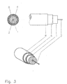
- Fig. 3 shows the waveguide assembly of Figures 1 or 2, which is additionally sheathed with a Isolierstoffmantel 8, which may consist of the same material as the storage 1, d. h preferably made of plastic, such as. Polymer or elastomer, but in denser form, e.g. with or without fewer pores.
- a Isolierstoffmantel 8 which may consist of the same material as the storage 1, d. h preferably made of plastic, such as. Polymer or elastomer, but in denser form, e.g. with or without fewer pores.
- the insulating jacket 1 surrounding the bearing 1 serves, on the one hand, for the electrical insulation between the waveguide 2 and the coaxial return conductor 4 and, on the other hand, the mechanical insulation against external mechanical or acoustic interference.
- the waveguide arrangement shown in FIG. 4 provides a return conductor foil 9, which is arranged between the bearing 1 and the coaxial return conductor 4.
- the outer Isolierstoffmantel 8 is similar to the material properties of the inner insulation 1 and is also characterized by the highest possible gas / solids ratio.
- the outer Isolierstoffmantel 8 is also made of foamed, cellular, insulating material here.
- Both for the storage 1 and for the Isolierstoffmantel 8 usable plastic materials are from the group of polymers z.
- FEP fluoroethylene copolymer
- PTFE polytetrafluoroethylene
- PVC polyvinyl chloride
- PA polyamide
- PE polyethylene
- PP polypropylene
- SPE fuoamed polyethylene
- FIG. 5 shows a waveguide arrangement with a coaxial return conductor 4, with a hollow cylindrical bearing 1 for a waveguide 2, and an insulating jacket 8. These elements correspond to those of FIG. 4.
- a wire-shaped bearing 10 is wound spirally around the waveguide 2, which preferably also consists of cell-shaped structured material, which supports the waveguide 2 and centered in the cylindrical interior 19 of the bearing 1.
- the contact surfaces between the wire-shaped bearing 10 and the waveguide 2 are minimal.
- the spiral wrapping of the waveguide 2 allows a further reduction of the bearing surface between the bearing 10 and waveguide 2, and thus a lower damping effect on the waveguide.
- the wire-shaped bearing 10 contacts the inner periphery 17 of the bearing 1 at other contact surfaces 26. These can be attached to the storage 10, z. B. for better support, be widened foot (not shown).
- FIG. 1 Another embodiment of a spiral bearing is shown in FIG. There, too, guided in the center of the arrangement waveguide 2 is surrounded by a band-shaped bearing 11 spirally and is supported by this.
- the band-shaped bearing 11 is here, however, arranged centrally together with the waveguide 2 in the interior 19 of the tubular return conductor 4. In this case, the band-shaped bearing 11 is supported on the inner circumference 17 of the electrical return conductor 4.
- the coaxial return conductor 4 may have a smooth surface or, as shown here, a corrugated surface at its inner or outer periphery 17, 18.
- the waves may be formed by single coaxial constrictions, or generated by a single helical constriction. By this design, the tubular wavy return conductor 4 can be bent more easily and laid in radii.
- FIG. 7 shows a waveguide arrangement similar to the arrangement in FIG. 4, with a waveguide 2, a bearing 1, a coaxial return conductor foil 9 and an electrical return conductor 4, which is surrounded by an insulating jacket 8.
- an extension 12 is formed, which receives a support wire 13 made of steel.
- a support wire 13 made of steel.
- other fastening means such as bars of different materials, serve.
- the fastening means are preferably elongate, in the longitudinal direction of the waveguide 2, that is, parallel to the waveguide 2, extending elements, which are preferably arranged in a partial region of the insulating jacket 8.
- FIG. 8 shows a multilayer waveguide arrangement with a filling material 15 in which auxiliary electrical conductors 14 are embedded.
- the coaxial waveguide assembly comprises a waveguide 2, a bearing 1, a coaxial return conductor foil 9 coaxially surrounded by the filling material 15, and a coaxial insulating jacket 8 (from inside to outside).
- one or more electrical auxiliary conductors 14 may be embedded, which preferably extend parallel to the waveguide 2. Electric fields generated by current pulses in the auxiliary conductors 14 are shielded from the waveguide 2 in a known manner by the coaxial line consisting of waveguide 2 and electrical return conductor foil 9.
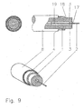
- the embodiment of a waveguide arrangement with coaxial electrical return conductor 4 shown in FIG. 9 provides for the coaxial bearing 1 between waveguide 2 and the electrical coaxial return conductor 4 to be provided by annular webs 3, wherein the webs 3 are arranged at as great distances as possible and as small as possible Bridge width, d. h., Should have as small a contact surface on the waveguide 2.
- the annular webs 3 protrude beyond the inner circumference 17 of the bearing 1 at least partially into the inner space 19 of the bearing 1. At least the inner end portions of the webs 3 are wedge-shaped, tapered and designed so that the waveguide is mechanically held, but only a small contact bearing surface between the waveguide 2 and the insulating material of the webs 3 is to minimize the mechanical To cause waves and on the other hand to counteract acting on the outside of the arrangement mechanical disturbances in the form of vibration, shock, or shock pulses dampening.
- the waveguide 2 does not lie on the inner circumference 17 of the bearing 1.
- the web distances are chosen so that a slack between the webs does not interfere with the measurement accuracy.
- the webs 3 consist of the same cell-like structured material as the storage 1 and are integrally formed with the storage 1, which may be open-pore or closed-pore.
- the webs 3 are formed integrally with the bearing 1 (FIG. 9).
- the webs 3 are preferably arranged at right angles to the direction of extension of the waveguide 2.
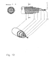
- Fig. 10 shows a further embodiment of a waveguide arrangement with a wire-shaped electrical return conductor 5, wherein the end of a sleeve 20 is provided, which is preferably magnetically and electrically conductive and the waveguide 2 to the wire-shaped electrical return conductor 5 electrically connected, wherein the wire-shaped electrical return conductor 5 is embedded in an outer region of the coaxial, hollow cylindrical bearing 1.
- the waveguide 2 is shielded by a coaxial shield 21 against electromagnetic fields, which is further isolated from a coaxial Isolierstoffmantel 8 electrically and mechanically against external disturbances.
- the electrical connection between the electrical return conductor 5 and the end 6 of the waveguide 2 can also be produced by soldering, welding, pressing, etc.
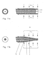
- 11a and 11b show a view of a waveguide arrangement with a coaxial electrical return conductor 4 for explaining the production of a damping region while contacting the mechanical waveguide 2 with the coaxial electrical return conductor 4th
- the waveguide arrangement in FIG. 11 a comprises a waveguide 2, which is guided centrally in a hollow-cylindrical bearing 1 and protrudes axially beyond an end face 23 of the bearing 1.
- the ferrule 22 is pressed in a known manner by suitable tools conical concentric with the insulating material on the waveguide 2, thereby simultaneously a contact between the mechanical waveguide 2 and the coaxial or biaxial electrical return conductor arises.
- the compression of the storage material leads to an increased damping effect and suppresses unwanted reflections of mechanical waves in the region of the free end 6 of the waveguide second
Landscapes
- Physics & Mathematics (AREA)
- General Physics & Mathematics (AREA)
- Waveguides (AREA)
- Magnetic Bearings And Hydrostatic Bearings (AREA)
- Measurement Of Mechanical Vibrations Or Ultrasonic Waves (AREA)
Claims (15)
- Support (1) pour un guide d'onde (2) qui sert à l'acheminement d'ondes mécaniques, le support (1) présentant une grande part de gaz et une part plus faible de substances solides, dans le fait qu'il est structuré en forme des cellules sous inclusion de parts de gaz,
caractérisé en ce que- le support (1) entoure complètement le guide d'ondes (2).- et que le support étant réalisé d'une seule pièce. - Support (1) selon la revendication 1, caractérisé en ce que le support (1) comporte plusieurs talons (3) disposés à distance le long du guide d'ondes (2) de sorte que le guide d'ondes (2) est entouré de gaz dans les intervalles entre les talons (3), les talons (3) étant réalisés d'une seule pièce avec le support (1).
- Support (1) selon l'une des revendications précédentes, caractérisé en ce que les talons (3) ont une surface d'application la plus petite possible sur le guide d'ondes (2) et sont disposés à des intervalles les plus grands possible.
- Support (1) selon l'une des revendications précédentes, caractérisé en ce que le support (1) présente une densité la plus faible possible.
- Support (1) selon l'une des revendications précédentes, caractérisé en ce que le support (1) est autoportant.
- Support (1) selon l'une des revendications précédentes caractérisé en ce que le support (1) se compose de matière synthétique.
- Support (1) selon l'une des revendications précédentes caractérisé en ce que le support (1) présente une structure cellulaire à pores ouverts ou pores fermés.
- Support (1) selon l'une des revendications précédentes, caractérisé en ce que le support (1) est disposé entre le guide d'ondes (2) et un conducteur de retour électrique (4) d'un capteur de position travaillant selon le principe du temps de propagation des ondes mécaniques, le conducteur disposé coaxialement autour du guide d'ondes (2).
- Support (1) selon la revendication 8, caractérisé en ce que le support (1) est disposé sur toute la longueur du guide d'ondes (2) entre le guide d'ondes (2) et un conducteur de retour électrique (4) d'un capteur de position travaillant selon le principe du temps de propagation des ondes mécaniques, le conducteur étant disposé coaxialement autour du guide d'ondes (2).
- Support (1) selon l'une des revendications 1 à 7, caractérisé en ce qu'un conducteur de retour électrique (5) en forme de fil d'un capteur de position est enrobé dans le support (1).
- Support (1) selon l'une des revendications précédentes, caractérisé en ce que le support (1) est renforcé par des moyens stabilisateurs de forme, en particulier des fibres.
- Support (1) selon l'une des revendications précédentes, caractérisé en ce que le support (1) présente dans la zone de l'extrémité libre (6) du guide d'ondes (2) une action d'absorption plus élevée que dans la zone médiane du guide d'ondes (2) pour des ondes mécaniques qui se propagent le long du guide d'ondes (2) pour absorber des réflexions indésirables d'ondes mécaniques aux extrémités libres (6) du guide d'ondes (2).
- Support (1) selon l'une des revendications précédentes, caractérisé en ce que le support (1) présente dans la zone de l'extrémité libre (6) du guide d'onde (2) une structure cellulaire plus dense que dans la zone médiane du guide d'ondes (2) pour absorber des réflexions indésirables d'ondes mécaniques à l'extrémité libre (6) du guide d'ondes (2).
- Support (1) selon l'une des revendications précédentes, caractérisé en ce que l'extrémité libre (6) du guide d'onde (2) est protégée contre les influences de l'environnement en particulier à la liaison entre le guide d'ondes (2) et le conducteur de retour électrique (4, 5, 9).
- Support (1) selon l'une des revendications précédentes, caractérisé en ce que le support (1) présente une part d'au moins 50 % en volume gazeux et au moins 50 % en volume de substances solides.
Applications Claiming Priority (2)
| Application Number | Priority Date | Filing Date | Title |
|---|---|---|---|
| DE19753805A DE19753805C2 (de) | 1997-12-03 | 1997-12-03 | Lagerung für Wellenleiter zur Fortleitung mechanischer Wellen und Verfahren zur Herstellung |
| DE19753805 | 1997-12-03 |
Publications (3)
| Publication Number | Publication Date |
|---|---|
| EP0921373A2 EP0921373A2 (fr) | 1999-06-09 |
| EP0921373A3 EP0921373A3 (fr) | 2000-06-14 |
| EP0921373B1 true EP0921373B1 (fr) | 2006-11-22 |
Family
ID=7850733
Family Applications (1)
| Application Number | Title | Priority Date | Filing Date |
|---|---|---|---|
| EP98122618A Expired - Lifetime EP0921373B1 (fr) | 1997-12-03 | 1998-11-27 | Support pour un guide d' ondes mécaniques |
Country Status (4)
| Country | Link |
|---|---|
| US (1) | US6185155B1 (fr) |
| EP (1) | EP0921373B1 (fr) |
| DE (2) | DE19753805C2 (fr) |
| ES (1) | ES2276446T3 (fr) |
Families Citing this family (27)
| Publication number | Priority date | Publication date | Assignee | Title |
|---|---|---|---|---|
| EP1306859B1 (fr) * | 2001-10-22 | 2007-01-10 | Nexans | Câble comprenant une gaine de câble extrudée et un procédé pour la fabrication d'un tel câble |
| US20040049208A1 (en) * | 2002-04-03 | 2004-03-11 | Thomas Fogarty, M.D. | Methods and systems for vein harvesting and fistula creation |
| US20060258996A1 (en) * | 2003-06-05 | 2006-11-16 | Opie John C | Surgical drains |
| DE10348195B4 (de) * | 2003-10-16 | 2011-08-11 | ASM Automation Sensorik Meßtechnik GmbH, 85452 | Sensor nach dem Laufzeitprinzip mit einer Detektoreinheit für mechanisch-elastische Wellen |
| US7239129B2 (en) | 2003-10-16 | 2007-07-03 | Asm Automation Sensorik Messtechnik Gmbh | Sensor based on the travel time principle with a detector unit for mechanically elastic waves |
| US7142752B2 (en) * | 2004-04-30 | 2006-11-28 | Corning Cable Systems Llc | Buffered optical waveguides |
| US20050244113A1 (en) * | 2004-04-30 | 2005-11-03 | Chiasson David W | Buffered optical waveguides |
| EP1750589A2 (fr) * | 2004-05-13 | 2007-02-14 | Medtronic, Inc. | Element de prelevement de veine percutane dote d'une lame protegee |
| DE102005039661B4 (de) * | 2005-08-22 | 2008-07-24 | Asm Automation Sensorik Messtechnik Gmbh | Lagerungsmaterial |
| US9144185B1 (en) | 2009-02-02 | 2015-09-22 | Conductive Composites Company, L.L.C. | Method for manufacturing a panel for reflective broadband electromagnetic shield |
| WO2011124238A1 (fr) * | 2010-04-09 | 2011-10-13 | Hydac Electronic Gmbh | Système d'atténuation de l'onde de réflexion à l'extrémité ouverte d'un système de capteurs magnétostrictif |
| DE102010039055A1 (de) | 2010-08-09 | 2012-02-09 | Balluff Gmbh | Wegmessvorrichtung |
| JP6282266B2 (ja) * | 2013-04-03 | 2018-02-21 | ソニーセミコンダクタソリューションズ株式会社 | 導波管、導波管の製造方法、及び、無線伝送システム |
| DE102013009221A1 (de) | 2013-05-31 | 2014-12-04 | Fafnir Gmbh | Vorrichtung zur magnetostriktiven Positionsmessung |
| WO2015066494A2 (fr) * | 2013-11-01 | 2015-05-07 | Etegent Technologies Ltd. | Guide d'ondes à large bande |
| US10852277B2 (en) | 2014-04-09 | 2020-12-01 | Etegent Technologies, Ltd. | Active waveguide excitation and compensation |
| WO2016141967A1 (fr) | 2015-03-09 | 2016-09-15 | Balluff Gmbh | Dispositif de mesure de déplacement magnétostrictif et procédé pour faire fonctionner un dispositif de mesure de déplacement magnétostrictif |
| US10257965B1 (en) | 2016-07-01 | 2019-04-09 | Conductive Composites Company Ip, Llc | Electromagnetically shielded coverings for optical openings |
| DE102016114561A1 (de) * | 2016-08-05 | 2018-02-08 | Balluff Gmbh | Magnetostriktive Wegmessvorrichtung und Verfahren zur Herstellung eines Messfühlers einer magnetostriktiven Wegmessvorrichtung |
| DE102016118522B4 (de) | 2016-09-29 | 2021-03-25 | Sick Atech Gmbh | Positionssensor |
| DE102016118524A1 (de) | 2016-09-29 | 2018-03-29 | Sick Atech Gmbh | Positionssensor |
| DE102016125878A1 (de) | 2016-12-29 | 2018-07-05 | Sick Atech Gmbh | Positionssensor |
| US11686627B2 (en) | 2017-04-10 | 2023-06-27 | Etegent Technologies Ltd. | Distributed active mechanical waveguide sensor driven at multiple frequencies and including frequency-dependent reflectors |
| CN208819632U (zh) * | 2018-04-25 | 2019-05-03 | 深圳市安拓浦科技有限公司 | 一体化输出线路及其应用的天线系统 |
| CN108594311A (zh) * | 2018-06-11 | 2018-09-28 | 中国石油天然气集团公司 | 一种基于磁致伸缩线缆的谐波源检测装置及方法 |
| US10669436B1 (en) | 2018-11-16 | 2020-06-02 | Conductive Composites Company Ip, Llc | Multifunctional paints and caulks with controllable electromagnetic properties |
| DE102022106286A1 (de) | 2022-03-17 | 2023-09-21 | Sick Ag | Verfahren zum Herstellen eines Messelementes eines magnetostriktiven Sensors |
Citations (1)
| Publication number | Priority date | Publication date | Assignee | Title |
|---|---|---|---|---|
| US3898555A (en) * | 1973-12-19 | 1975-08-05 | Tempo Instr Inc | Linear distance measuring device using a moveable magnet interacting with a sonic waveguide |
Family Cites Families (11)
| Publication number | Priority date | Publication date | Assignee | Title |
|---|---|---|---|---|
| US3965448A (en) * | 1975-05-07 | 1976-06-22 | The United States Of America As Represented By The Secretary Of The Navy | Waveguide isolator with damping means |
| DE2541243A1 (de) * | 1975-09-12 | 1977-03-24 | Aeg Telefunken Kabelwerke | Hochfrequenz-koaxialleitung |
| JPS54162280A (en) * | 1978-06-13 | 1979-12-22 | Nippon Denshi Kogyo Kk | Transmission cable of ultrasoniccwave device |
| DE2830611C3 (de) * | 1978-07-12 | 1982-01-14 | Felten & Guilleaume Carlswerk AG, 5000 Köln | Längs- und querwassersicheres koaxiales Hochfrequenzkabel |
| DE3268193D1 (en) * | 1981-01-27 | 1986-02-13 | Atomic Energy Authority Uk | Ultrasonic transducers |
| US4442515A (en) * | 1981-12-17 | 1984-04-10 | Ford Motor Company | Multiplex transmission medium for application in multiplex vehicle control systems |
| US4450376A (en) * | 1981-12-17 | 1984-05-22 | Ford Motor Company | Transmission medium for application in electrical and acoustical control systems |
| DE3343310C2 (de) * | 1983-11-30 | 1987-01-29 | Gebhard Balluff Fabrik feinmechanischer Erzeugnisse GmbH & Co, 7303 Neuhausen | Ultraschall-Wegmesser |
| WO1988009917A1 (fr) * | 1987-06-04 | 1988-12-15 | Walter Lukosz | Procede de modulation optique et de mesure |
| US5590091A (en) * | 1995-05-11 | 1996-12-31 | Mts Systems Corporation | Waveguide suspension device and modular construction for sonic waveguides |
| EP1331471A2 (fr) * | 1995-05-11 | 2003-07-30 | Mts Systems Corporation | Capteur avec un guide d'onde et un conducteur de retour |
-
1997
- 1997-12-03 DE DE19753805A patent/DE19753805C2/de not_active Expired - Lifetime
-
1998
- 1998-11-27 DE DE59813819T patent/DE59813819D1/de not_active Expired - Lifetime
- 1998-11-27 EP EP98122618A patent/EP0921373B1/fr not_active Expired - Lifetime
- 1998-11-27 ES ES98122618T patent/ES2276446T3/es not_active Expired - Lifetime
- 1998-12-03 US US09/204,574 patent/US6185155B1/en not_active Expired - Lifetime
Patent Citations (1)
| Publication number | Priority date | Publication date | Assignee | Title |
|---|---|---|---|---|
| US3898555A (en) * | 1973-12-19 | 1975-08-05 | Tempo Instr Inc | Linear distance measuring device using a moveable magnet interacting with a sonic waveguide |
Also Published As
| Publication number | Publication date |
|---|---|
| ES2276446T3 (es) | 2007-06-16 |
| EP0921373A3 (fr) | 2000-06-14 |
| US6185155B1 (en) | 2001-02-06 |
| DE19753805C2 (de) | 1999-09-30 |
| DE19753805A1 (de) | 1999-06-17 |
| EP0921373A2 (fr) | 1999-06-09 |
| DE59813819D1 (de) | 2007-01-04 |
Similar Documents
| Publication | Publication Date | Title |
|---|---|---|
| DE19753805C2 (de) | Lagerung für Wellenleiter zur Fortleitung mechanischer Wellen und Verfahren zur Herstellung | |
| DE69005639T2 (de) | Einziehbares gewendeltes elektrisches kabel. | |
| EP2019394B1 (fr) | Câble électrique flexible | |
| DE602004004108T2 (de) | Kabel mit einem stark ausgedehnten Schaumstoff aus einem Polymermaterial mit ultrahohem Strangaufweitungsverhältnis | |
| DE3882332T2 (de) | Wasserunempfindliches Nachrichtenkabel. | |
| DE68908881T2 (de) | Verstärktes elektrisches koaxialkabel mit niedriger dielektrischer konstante. | |
| EP2031604A2 (fr) | Câble électrique flexible | |
| EP2187405B1 (fr) | Câble électrique flexible | |
| DE3620595A1 (de) | Kabel | |
| EP1398799B1 (fr) | Câble électrique pour la connexion de charges électriques mobiles | |
| EP3306740A1 (fr) | Câble de guide d'ondes diélectrique | |
| DE4110124A1 (de) | Isoliermaterial fuer rohrleitungen | |
| DE10315609A1 (de) | Datenübertragungskabel | |
| EP1451497B1 (fr) | Tuyau en matiere plastique, notamment tuyau pneumatique | |
| EP1163684A1 (fr) | Blindage de cable constitue de materiaux renforces par des fibres | |
| EP1158638B1 (fr) | Ensemble de connexion électrique de conducteurs de deux câbles haute tension | |
| DE10348195B4 (de) | Sensor nach dem Laufzeitprinzip mit einer Detektoreinheit für mechanisch-elastische Wellen | |
| DE102013009221A1 (de) | Vorrichtung zur magnetostriktiven Positionsmessung | |
| WO2012136822A2 (fr) | Ligne électrique pour transmettre des signaux de données | |
| EP0330278B1 (fr) | Câble optique sous marin | |
| DE9321083U1 (de) | Energieübertragungskabel mit Lichtwellenleiterelement | |
| DE102014014793B4 (de) | Kabel hoher Steifigkeit und dessen Verwendung | |
| DE4403266C1 (de) | Energiekabel | |
| DE2811579A1 (de) | Feuchtigkeitsgeschuetztes elektrisches kunststoffisoliertes energiekabel | |
| DE9413136U1 (de) | Koaxiales Hochfrequenz-Kabel |
Legal Events
| Date | Code | Title | Description |
|---|---|---|---|
| PUAI | Public reference made under article 153(3) epc to a published international application that has entered the european phase |
Free format text: ORIGINAL CODE: 0009012 |
|
| AK | Designated contracting states |
Kind code of ref document: A2 Designated state(s): DE ES FR GB IT |
|
| AX | Request for extension of the european patent |
Free format text: AL;LT;LV;MK;RO;SI |
|
| PUAL | Search report despatched |
Free format text: ORIGINAL CODE: 0009013 |
|
| AK | Designated contracting states |
Kind code of ref document: A3 Designated state(s): AT BE CH CY DE DK ES FI FR GB GR IE IT LI LU MC NL PT SE |
|
| AX | Request for extension of the european patent |
Free format text: AL;LT;LV;MK;RO;SI |
|
| RIC1 | Information provided on ipc code assigned before grant |
Free format text: 7G 01B 17/00 A, 7G 10K 11/24 B |
|
| 17P | Request for examination filed |
Effective date: 20000623 |
|
| AKX | Designation fees paid |
Free format text: DE ES FR GB IT |
|
| RAP1 | Party data changed (applicant data changed or rights of an application transferred) |
Owner name: ASM AUTOMATION SENSORIK MESSTECHNIK GMBH |
|
| 17Q | First examination report despatched |
Effective date: 20031016 |
|
| GRAP | Despatch of communication of intention to grant a patent |
Free format text: ORIGINAL CODE: EPIDOSNIGR1 |
|
| RTI1 | Title (correction) |
Free format text: SUPPORT FOR A WAVEGUIDE CONDUCTING MECHANICAL WAVES |
|
| GRAS | Grant fee paid |
Free format text: ORIGINAL CODE: EPIDOSNIGR3 |
|
| GRAA | (expected) grant |
Free format text: ORIGINAL CODE: 0009210 |
|
| AK | Designated contracting states |
Kind code of ref document: B1 Designated state(s): DE ES FR GB IT |
|
| REG | Reference to a national code |
Ref country code: GB Ref legal event code: FG4D Free format text: NOT ENGLISH |
|
| PGFP | Annual fee paid to national office [announced via postgrant information from national office to epo] |
Ref country code: ES Payment date: 20061220 Year of fee payment: 9 |
|
| REF | Corresponds to: |
Ref document number: 59813819 Country of ref document: DE Date of ref document: 20070104 Kind code of ref document: P |
|
| GBT | Gb: translation of ep patent filed (gb section 77(6)(a)/1977) |
Effective date: 20070214 |
|
| ET | Fr: translation filed | ||
| REG | Reference to a national code |
Ref country code: ES Ref legal event code: FG2A Ref document number: 2276446 Country of ref document: ES Kind code of ref document: T3 |
|
| PLBE | No opposition filed within time limit |
Free format text: ORIGINAL CODE: 0009261 |
|
| STAA | Information on the status of an ep patent application or granted ep patent |
Free format text: STATUS: NO OPPOSITION FILED WITHIN TIME LIMIT |
|
| 26N | No opposition filed |
Effective date: 20070823 |
|
| REG | Reference to a national code |
Ref country code: ES Ref legal event code: FD2A Effective date: 20071128 |
|
| PG25 | Lapsed in a contracting state [announced via postgrant information from national office to epo] |
Ref country code: ES Free format text: LAPSE BECAUSE OF NON-PAYMENT OF DUE FEES Effective date: 20071128 |
|
| REG | Reference to a national code |
Ref country code: DE Ref legal event code: R082 Ref document number: 59813819 Country of ref document: DE Representative=s name: WEICKMANN & WEICKMANN PATENT- UND RECHTSANWAEL, DE Ref country code: DE Ref legal event code: R082 Ref document number: 59813819 Country of ref document: DE Representative=s name: WEICKMANN & WEICKMANN PATENTANWAELTE - RECHTSA, DE Ref country code: DE Ref legal event code: R082 Ref document number: 59813819 Country of ref document: DE Representative=s name: PATENTANWAELTE WEICKMANN & WEICKMANN, DE |
|
| REG | Reference to a national code |
Ref country code: FR Ref legal event code: PLFP Year of fee payment: 18 |
|
| REG | Reference to a national code |
Ref country code: FR Ref legal event code: PLFP Year of fee payment: 19 |
|
| REG | Reference to a national code |
Ref country code: FR Ref legal event code: PLFP Year of fee payment: 20 |
|
| PGFP | Annual fee paid to national office [announced via postgrant information from national office to epo] |
Ref country code: DE Payment date: 20171127 Year of fee payment: 20 Ref country code: FR Payment date: 20171124 Year of fee payment: 20 |
|
| PGFP | Annual fee paid to national office [announced via postgrant information from national office to epo] |
Ref country code: IT Payment date: 20171122 Year of fee payment: 20 Ref country code: GB Payment date: 20171124 Year of fee payment: 20 |
|
| REG | Reference to a national code |
Ref country code: DE Ref legal event code: R071 Ref document number: 59813819 Country of ref document: DE |
|
| REG | Reference to a national code |
Ref country code: GB Ref legal event code: PE20 Expiry date: 20181126 |
|
| PG25 | Lapsed in a contracting state [announced via postgrant information from national office to epo] |
Ref country code: GB Free format text: LAPSE BECAUSE OF EXPIRATION OF PROTECTION Effective date: 20181126 |