EP0921382A2 - Senseur optique de front d'onde du type Hartmann - Google Patents
Senseur optique de front d'onde du type Hartmann Download PDFInfo
- Publication number
- EP0921382A2 EP0921382A2 EP98122562A EP98122562A EP0921382A2 EP 0921382 A2 EP0921382 A2 EP 0921382A2 EP 98122562 A EP98122562 A EP 98122562A EP 98122562 A EP98122562 A EP 98122562A EP 0921382 A2 EP0921382 A2 EP 0921382A2
- Authority
- EP
- European Patent Office
- Prior art keywords
- array
- cells
- lenslet
- interest
- sensor array
- Prior art date
- Legal status (The legal status is an assumption and is not a legal conclusion. Google has not performed a legal analysis and makes no representation as to the accuracy of the status listed.)
- Granted
Links
Images


Classifications
-
- G—PHYSICS
- G02—OPTICS
- G02B—OPTICAL ELEMENTS, SYSTEMS OR APPARATUS
- G02B26/00—Optical devices or arrangements for the control of light using movable or deformable optical elements
- G02B26/06—Optical devices or arrangements for the control of light using movable or deformable optical elements for controlling the phase of light
-
- G—PHYSICS
- G01—MEASURING; TESTING
- G01J—MEASUREMENT OF INTENSITY, VELOCITY, SPECTRAL CONTENT, POLARISATION, PHASE OR PULSE CHARACTERISTICS OF INFRARED, VISIBLE OR ULTRAVIOLET LIGHT; COLORIMETRY; RADIATION PYROMETRY
- G01J9/00—Measuring optical phase difference; Determining degree of coherence; Measuring optical wavelength
Definitions
- This invention relates generally to adaptive optics systems and, more particularly, to techniques for measuring relative phase tilt of an optical beam in two dimensions across a planar array.
- Adaptive optics systems employ adjustable optical elements, such as deformable mirrors, to compensate for aberrations in an optical beam. Aberrations may be caused, for example, by propagation of the beam through the atmosphere.
- the aberrated beam is reflected from a deformable mirror having many small elements that are adjustable in position, using a separate actuator associated with each movable mirror element. Part of the reflected beam is split off and directed to impinge on a sensor array, which provides measurements indicative of wavefront distortion in the reflected beam. The wavefront distortion measurements are then fed back to the deformable mirror to provide continuous corrections by appropriately moving the mirror elements.
- the principal components of a wavefront sensor array are an array of small lenses, referred to as a lenslet array, and camera having an array of sensor elements. This configuration is referred to as the Shack-Hartmann wavefront sensor.
- the lenslet array when disposed in the path of the beam, produces multiple elemental portions of the beam, referred to as subapertured portions. Each lenslet in the lenslet array processes a subaperture of the whole beam.
- the lenslet array typically has each of its lenslets positioned on a square grid, although the whole array may not be square, and is usually a polygon shape conforming approximately to the outline of a circular beam.
- the camera sensor elements are usually square or rectangular in shape and are also usually arranged in a square or rectangular grid pattern, angularly aligned to be parallel with the lenslet grid pattern.
- each subaperture or lenslet is centered equidistantly with respect to the positions of four adjacent mirror actuators.
- the lenslet is centered over a group of four camera sensor elements, referred to as a quad-cell.
- a measure of phase tilt in one direction is derived from the difference between signal outputs from each of two pairs of the cells in the quad-cell.
- the X-axis tilt is determined from [(A+C)- ( B+D)]/[A+B+C+D] .
- the Y-axis tilt is determined from [(A+B)- (C+D)]/[A+B+C+D] .
- the principal drawback of this approach is that it would be preferable to measure the local X-axis tilt between two adjacent actuators on a common X axis, and to measure the Y-axis tilt between two adjacent actuators on a common Y-axis.
- An alternate configuration of the prior art avoids this disadvantage but, unfortunately, introduces another difficulty.
- two lenslet arrays and two arrays of detectors are needed, one to measure the X-axis tilt and the other to measure the Y-axis tilt.
- the lenslet array for measuring the X-axis tilt is positioned such that each subaperture or lenslet is positioned midway between the grid positions corresponding to two adjacent actuators on a common X axis.
- each subaperture or lenslet is positioned midway between the grid positions corresponding to two adjacent actuators on a common Y axis.
- a camera sensor array provides a bi-cell, i.e. two adjacent sensor cells located between the adjacent actuators in the common X axis. Light from the lenslet is, therefore, normally positioned over the boundary between the two cells in the bi-cell, and any tilt in the X-axis direction is determined from the difference in output signals from the two cells in the bi-cell.
- a separate camera sensor array provides a bi-cell between two grid positions corresponding the adjacent actuators in the common Y axis.
- Y-axis tilt is derived from the difference between output signals from two cells in the bi-cell.
- the difficulty introduced by this configuration is that two lenslet arrays and two cameras are required.
- the two lenslet arrays will necessarily interfere with each other physically if they are placed in a single beam being analyzed.
- Use of beam splitters to provide two separate beams for analysis by the two lenslet arrays and cameras introduces further complications in terms of alignment.
- the present invention resides in a wavefront sensor for use in measuring local phase tilt in two dimensions over an optical beam cross section, using only one lenslet array and one camera sensor array. The measurements are made with respect to first and second orthogonal sets of grid lines intersecting at points of interest corresponding to positions of optical device actuators.
- the wavefront sensor of the invention comprises a lenslet array and a camera sensor array.
- the lenslet array has a plurality of lenslets with optical axes positioned on points of intersection of a rectangular grid, which is oriented at an angle to the first and second orthogonal sets of grid lines, wherein the lenslets are spaced in such a manner that the lenslet optical axes are positioned on the first and second orthogonal sets of grid lines, between adjacent points of interest at the intersections of those lines.
- the camera sensor array has a plurality of sensor cells disposed in a rows and columns oriented parallel with the first and second orthogonal sets of grid lines and positioned adjacent to the lenslet array to receive light passing through the lenslets.
- the camera sensor array is a rectangular array of bi-cells, each of which is approximately one-fourth the area of a square defined by four adjacent points of interest. Only alternate bi-cells in each column and row of the sensor array are activated; and each active bi-cell is positioned at the mid-point of a line between two adjacent points of interest, to measure the tilt with respect to the direction of that line.
- each bi-cell pixel is approximately square.
- the camera sensor array is a rectangular array of cells, each of which is approximately one-ninth the area of a square defined by four adjacent points of interest.
- only selected adjacent pairs of cells in each column and row of the sensor array are activated, to form active bi-cells spaced along the orthogonal sets of grid lines. Only four of every nine cells are activated and each active bi-cell is positioned at the approximate mid-point of a line between two adjacent points of interest, to measure the tilt with respect to the direction of that line.
- each cell is approximately square.
- the rectangular array defining the lenslet array is oriented at approximately 45 degrees to the camera sensor array and the first and second orthogonal sets of grid lines.
- the invention may also be defined as a method for measuring local phase tilt in two dimensions over an optical beam cross section, along first and second orthogonal sets of grid lines intersecting at points of interest corresponding to positions of optical device actuators.
- the method comprises the steps of passing a beam through a lenslet array having a plurality of lenslets formed on a rectangular grid; orienting the lenslet array with its rectangular grid of lenslets at an angle to the first and second orthogonal sets of grid lines; positioning the lenslet array such that each lenslet has a subaperture centered close to the midpoint of a line between two adjacent points of interest; placing a single camera sensor array next to the lenslet array to receive light therefrom, wherein the sensor array has a plurality of sensor cells greater in number, per unit area, than the number of lenslets per unit area; orienting the sensor array to coincide with the first and second sets of orthogonal grid lines; activating selected cells in the sensor array, wherein the selected cells are bicells positioned approximately over the center of each subaperture of the lens
- the camera sensor array is a rectangular array of bi-cells, each of which is approximately one-fourth the area of a square defined by four adjacent points of interest.
- the activating step includes activating only alternate bi-cells in each column and row of the sensor array, and each active bi-cell is positioned at the mid-point of a line between two adjacent points of interest, to measure the tilt with respect to the direction of that line.
- the camera sensor array is a rectangular array of cells, each of which is approximately one-ninth the area of a square defined by four adjacent points of interest
- the activating step includes activating only selected adjacent pairs of cells in each column and row of the sensor array, to form active bi-cells spaced along the orthogonal sets of grid lines. Only four of every nine cells are activated and each active bi-cell is positioned at the mid-point of a line between two adjacent points of interest, to measure the tilt with respect to the direction of that line.
- the step of orienting the lenslet array includes orienting it at an angle of approximately 45 degrees to the first and second orthogonal sets of grid lines.
- the present invention represents a significant advance in the field of wavefront sensors for use in adaptive optics systems.
- the invention provides two-dimensional measurements of phase tilt over the cross section of a beam, but using only a single lenslet array and a single camera sensor array.
- an adaptive optics system may include a deformable mirror of this general type, as indicated by reference numeral 10, and a wavefront sensor array 12.
- a light beam 14 incident on the deformable mirror 10 is reflected into beam splitter 16 providing two output beams 14a and 14b.
- the beam 14a is directed to a device (not shown) that makes use of the information carried by the beam. If the adaptive optics system is part of an astronomical telescope, for example, the beam 14a will be directed into conventional components of a telescope (not shown).
- the other output beam 14b impinges on the wavefront sensor array 12.
- Output signals from the array 12 are processed in an adaptive optics controller 18, which generates control signals on lines 20 to control the individual actuators 22 in the deformable mirror 10.
- the controller 18 deforms the mirror 10 in such a manner as to reduce the wavefront distortion to near zero.
- the principal components of the wavefront sensor array 12 are a lenslet array 26 and a camera sensor array 28, only portions of which are shown in the figure.
- the lenslet array 26 contains a large number of small lenses, referred to as lenslets, positioned on a rectangular grid pattern.
- one of the lenslets is positioned with its axis on centerline 30.
- FIG. 3 shows a fragmentary portion of the camera sensor array 28 in plan view, including a quad-cell comprising cells 28a, 28b, 28c and 28d.
- the lenslet array 26 is positioned with respect to the camera sensor array 28 such the each centerline of a lenslet passes through the center of a quad-cell, as indicated in the figure.
- the size of the quad-cell 28a-28d is such that its four corners correspond to the positions of four adjacent mirror actuators 22. These positions are referenced by numeral 22' in the drawings.
- each lenslet is referred to as a beam subaperture and, for purposes of explanation, each subaperture is considered to encompass a square area, in this case corresponding to the area of the quad-cell 28a-28d in FIG. 3.
- the center of the subaperture is the centerline 30.
- the degree of "tilt" of the beam in an X-axis direction and a Y-axis direction can be determined from the signals output from the four elements 28a-28d of the quad-cell.
- the arrows emanating from the center 30 of the quad-cell indicate the directions of X-axis and Y-axis tilt. More specifically, if the signals output from the quad-cell 28a-28d are A, B, C and D, respectively, the Y-axis tilt is proportional to: (A+B)-(C+D) (A+B+C+D) . Similarly, the X-axis tilt is proportional to: (A+C)-(B+D) (A+B+C+D) .
- the adaptive optics system controller 18 can make appropriate adjustments to the actuators 22 to eliminate the tilt in each direction.
- a significant difficulty with this configuration is that the tilt measurements are made at the center of each quad-cell, but these measurements have to be translated into corrections applied at the positions of the corners of the quad-cell, where the actuators are located.
- movement of any one of the actuators 22 at a corresponding corner 22' of the quad-cell results in a tilt change in both the X-axis and Y-axis directions, as measured at the center of the quad-cell.
- FIGS. 4 and 5 avoids the drawback of the configuration discussed above by providing two separated lenslet arrays and two corresponding camera sensor arrays, to make two sets of tilt measurements.
- a first lenslet array with centerline at 30x is positioned with its subaperture nominally over the center of a bi-cell 32e-32f that is part of a first camera sensor array 32.
- the bi-cell 32e-32f is also centered over a horizontal (X-axis) line joining two adjacent actuator positions 22', as shown in FIG. 4. If the electrical output signals generated by the cells 32e and 32f are E and F, respectively, the X-axis tilt of the subaperture beam is proportional to: E-F E+F .
- the second lenslet array has a center at 30y positioned at the mid-point between two adjacent actuator positions 22' on a Y-axis line.
- a second camera sensor array has a bi-cell 34g-34h also positioned over the centerline 30y to provide a measurement of the Y-axis tilt of the subaperture beam. If the bi-cell 34g-34h output signals are G and H, respectively, the Y-axis tilt is proportional to: G-H G+H .
- the two lenslet arrays in this configuration would interfere physically if placed in the same beam, so the usual approach is to employ an additional beam splitter (not shown) and to perform the X-axis and Y-axis tilt measurements with separate beams. This poses alignment difficulties that will almost inevitably have an adverse effect on performance. Moreover, the use of a second lenslet array and a second camera sensor array increases the total cost of the device.
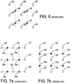
- FIGS. 6, 7a and 7b depict, for the two configurations of the prior art, the positional relationship between actuator positions 22' and the centerline positions of the lenslet arrays.
- each lenslet centerline 30 is positioned equidistantly from four adjacent actuator positions 22'.
- first lenslet centerline positions 30x are each positioned midway between adjacent actuator positions 22' on the same horizontal (X-axis) line
- second lenslet centerline positions 30y are positioned between adjacent actuator positions on the same vertical (Y-axis) line. It will also be apparent from FIGS.
- the lenslets in the lenslet arrays are all disposed on rectangular or square grid patters that are angularly aligned with the camera sensor array and with the grid pattern on which the actuator positions 22' are disposed.
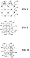
- a lenslet array with lenslet centerlines 40 is positioned with its grid pattern at 45 degrees to the grid pattern on which the actuator positions 22' are disposed, as depicted in FIG. 8, and a single camera sensor array 42 having selected X bi-cells 42a-42b and selected Y bi-cells 42c-42d positioned midway between adjacent actuator positions 22' in X-axis and the Y-axis, respectively, as depicted in FIG. 9. Because the bi-cells of the camera sensor array 42 are smaller, by a factor of two in at least one dimension, than those used in the configuration of FIGS. 4 and 5, both X-axis and Y-axis tilt measurements can be made without physical interference between the two sets of required bi-cells.
- the X-axis and Y-axis tilt measurements are derived from the output signals from the activated cells. Specifically, the X-axis tilt is proportional to outputs (A-B) derived from bi-cell 42a-42b, and the Y-axis tilt is proportional to output difference (C-D) derived from bi-cell 42c-42d.
- the camera sensor array referred to by numeral 44
- the camera sensor array has even smaller bi-cells.
- the invention provides the advantages of the prior art configuration of FIGS. 4 and 5, wherein tilt measurements in each axis are made midway between adjacent actuator positions in that axis, but only a single lenslet array and a single camera sensor array are needed. It will be appreciated, therefore, that the invention represents a significant advance in the field of wavefront sensors for use in adaptive optics systems. It will also be appreciated that, although the invention has been described in detail for purposes of illustration, various modifications may be made without departing from the spirit and scope of the invention. Accordingly, the invention should not be limited except as by the appended claims.
Landscapes
- Physics & Mathematics (AREA)
- General Physics & Mathematics (AREA)
- Spectroscopy & Molecular Physics (AREA)
- Optics & Photonics (AREA)
- Testing Of Optical Devices Or Fibers (AREA)
- Length Measuring Devices By Optical Means (AREA)
- Photometry And Measurement Of Optical Pulse Characteristics (AREA)
Applications Claiming Priority (2)
| Application Number | Priority Date | Filing Date | Title |
|---|---|---|---|
| US08/984,751 US5912731A (en) | 1997-12-04 | 1997-12-04 | Hartmann-type optical wavefront sensor |
| US984751 | 1997-12-04 |
Publications (3)
| Publication Number | Publication Date |
|---|---|
| EP0921382A2 true EP0921382A2 (fr) | 1999-06-09 |
| EP0921382A3 EP0921382A3 (fr) | 2000-04-05 |
| EP0921382B1 EP0921382B1 (fr) | 2004-08-11 |
Family
ID=25530824
Family Applications (1)
| Application Number | Title | Priority Date | Filing Date |
|---|---|---|---|
| EP98122562A Expired - Lifetime EP0921382B1 (fr) | 1997-12-04 | 1998-12-02 | Senseur optique de front d'onde du type Hartmann |
Country Status (6)
| Country | Link |
|---|---|
| US (1) | US5912731A (fr) |
| EP (1) | EP0921382B1 (fr) |
| JP (1) | JP3315086B2 (fr) |
| KR (1) | KR100300683B1 (fr) |
| CA (1) | CA2255197C (fr) |
| DE (1) | DE69825548T2 (fr) |
Cited By (2)
| Publication number | Priority date | Publication date | Assignee | Title |
|---|---|---|---|---|
| EP1199026A3 (fr) * | 2000-10-17 | 2003-07-02 | 20/10 Perfect Vision Optische Geraete GmbH | Système de distribution sans abérration |
| DE102014010667A1 (de) | 2014-07-18 | 2016-01-21 | Berliner Glas Kgaa Herbert Kubatz Gmbh & Co | Verfahren und Vorrichtung zur Messung der Form einer Wellenfront eines optischen Strahlungsfeldes |
Families Citing this family (36)
| Publication number | Priority date | Publication date | Assignee | Title |
|---|---|---|---|---|
| US6819414B1 (en) | 1998-05-19 | 2004-11-16 | Nikon Corporation | Aberration measuring apparatus, aberration measuring method, projection exposure apparatus having the same measuring apparatus, device manufacturing method using the same measuring method, and exposure method |
| US6376819B1 (en) * | 1999-07-09 | 2002-04-23 | Wavefront Sciences, Inc. | Sub-lens spatial resolution Shack-Hartmann wavefront sensing |
| US6304330B1 (en) * | 1999-10-06 | 2001-10-16 | Metrolaser, Inc. | Methods and apparatus for splitting, imaging, and measuring wavefronts in interferometry |
| JP4549468B2 (ja) * | 1999-12-28 | 2010-09-22 | 株式会社トプコン | レンズメータ |
| US6707020B1 (en) | 1999-12-28 | 2004-03-16 | Mza Associates Corporation | Adaptive dynamic range wavefront sensor |
| US6394999B1 (en) | 2000-03-13 | 2002-05-28 | Memphis Eye & Cataract Associates Ambulatory Surgery Center | Laser eye surgery system using wavefront sensor analysis to control digital micromirror device (DMD) mirror patterns |
| US7161128B2 (en) * | 2000-07-14 | 2007-01-09 | Adaptive Optics Associates, Inc. | Optical instrument employing a wavefront sensor capable of coarse and fine phase measurement capabilities during first and second modes of operation |
| US6649895B1 (en) | 2000-07-14 | 2003-11-18 | Adaptive Optics Associates, Inc. | Dispersed Hartmann sensor and method for mirror segment alignment and phasing |
| US6486943B1 (en) | 2000-09-19 | 2002-11-26 | The Schepens Eye Research Institute, Inc. | Methods and apparatus for measurement and correction of optical aberration |
| US6577447B1 (en) | 2000-10-20 | 2003-06-10 | Nikon Corporation | Multi-lens array of a wavefront sensor for reducing optical interference and method thereof |
| US6548797B1 (en) | 2000-10-20 | 2003-04-15 | Nikon Corporation | Apparatus and method for measuring a wavefront using a screen with apertures adjacent to a multi-lens array |
| WO2002046713A2 (fr) * | 2000-12-08 | 2002-06-13 | Cyberoptics Corporation | Systeme automatise a fonction de detection de hauteur amelioree |
| JPWO2002052620A1 (ja) * | 2000-12-22 | 2004-04-30 | 株式会社ニコン | 波面収差測定装置、波面収差測定方法、露光装置及びマイクロデバイスの製造方法 |
| JP2002198279A (ja) | 2000-12-25 | 2002-07-12 | Nikon Corp | 位置検出方法、光学特性測定方法、光学特性測定装置、露光装置、及びデバイス製造方法 |
| JP2002202220A (ja) | 2000-12-27 | 2002-07-19 | Nikon Corp | 位置検出方法、位置検出装置、光学特性測定方法、光学特性測定装置、露光装置、及びデバイス製造方法 |
| JP4345098B2 (ja) * | 2001-02-06 | 2009-10-14 | 株式会社ニコン | 露光装置及び露光方法、並びにデバイス製造方法 |
| US6784408B1 (en) | 2001-04-25 | 2004-08-31 | Oceanit Laboratories, Inc. | Array of lateral effect detectors for high-speed wavefront sensing and other applications |
| US7226166B2 (en) * | 2001-11-13 | 2007-06-05 | Philadelphia Retina Endowment Fund | Optimizing the properties of electromagnetic energy in a medium using stochastic parallel perturbation gradient descent optimization adaptive optics |
| US6648473B2 (en) | 2001-11-13 | 2003-11-18 | Philadelphia Retina Endowment Fund | High-resolution retina imaging and eye aberration diagnostics using stochastic parallel perturbation gradient descent optimization adaptive optics |
| US7377647B2 (en) * | 2001-11-13 | 2008-05-27 | Philadelphia Retina Endowment Fund | Clarifying an image of an object to perform a procedure on the object |
| US7775665B2 (en) * | 2001-11-13 | 2010-08-17 | Dellavecchia Michael A | Method for optically scanning objects |
| US20040165147A1 (en) * | 2001-11-13 | 2004-08-26 | Della Vecchia Michael A. | Determining iris biometric and spatial orientation of an iris in accordance with same |
| KR100419192B1 (ko) * | 2002-04-10 | 2004-02-21 | 한국수력원자력 주식회사 | 다중 입사광의 파면왜곡 정밀측정 장치 및 그 방법 |
| US20030234993A1 (en) * | 2002-06-21 | 2003-12-25 | Hazelton Andrew J. | Adaptive optic off-axis metrology |
| US6989922B2 (en) * | 2002-06-21 | 2006-01-24 | Nikon Corporation | Deformable mirror actuation system |
| US6840638B2 (en) * | 2002-07-03 | 2005-01-11 | Nikon Corporation | Deformable mirror with passive and active actuators |
| US6910770B2 (en) * | 2003-02-10 | 2005-06-28 | Visx, Incorporated | Eye refractor with active mirror wavefront sensor |
| US7343099B2 (en) * | 2004-02-12 | 2008-03-11 | Metrologic Instruments, Inc. | Free space optical (FSO) laser communication system employing fade mitigation measures based on laser beam speckle tracking and locking principles |
| US7187815B1 (en) * | 2004-10-01 | 2007-03-06 | Sandia Corporation | Relaying an optical wavefront |
| US7268937B1 (en) | 2005-05-27 | 2007-09-11 | United States Of America As Represented By The Secretary Of The Air Force | Holographic wavefront sensor |
| WO2007070006A1 (fr) * | 2005-12-13 | 2007-06-21 | Agency For Science, Technology And Research | Capteur de front d'onde optique |
| US7381934B2 (en) * | 2006-01-11 | 2008-06-03 | Xinetics, Inc. | Closed loop compensation system and method for a deformable mirror |
| WO2007106657A2 (fr) | 2006-03-14 | 2007-09-20 | Amo Manufacturing Usa, Llc | Système et procédé de capteur de front d'onde de fréquence spatiale |
| US7626152B2 (en) * | 2006-08-16 | 2009-12-01 | Raytheon Company | Beam director and control system for a high energy laser within a conformal window |
| WO2014018584A1 (fr) * | 2012-07-24 | 2014-01-30 | Trustees Of Boston University | Procédé et système d'imagerie de front d'onde à ouverture partitionnée |
| CN110455420B (zh) * | 2019-07-11 | 2021-12-07 | 长春理工大学 | 波前测量设备 |
Family Cites Families (6)
| Publication number | Priority date | Publication date | Assignee | Title |
|---|---|---|---|---|
| US4141652A (en) * | 1977-11-25 | 1979-02-27 | Adaptive Optics Associates, Inc. | Sensor system for detecting wavefront distortion in a return beam of light |
| FR2665955B1 (fr) * | 1985-11-20 | 1993-04-23 | Onera (Off Nat Aerospatiale) | Analyseur opto electronique de surfaces d'onde a mosauique de micro-lentilles. |
| US4967063A (en) * | 1988-06-16 | 1990-10-30 | The Aerospace Corporation | Charge controlled adaptive-optics system |
| US5229889A (en) * | 1991-12-10 | 1993-07-20 | Hughes Aircraft Company | Simple adaptive optical system |
| US5233174A (en) * | 1992-03-11 | 1993-08-03 | Hughes Danbury Optical Systems, Inc. | Wavefront sensor having a lenslet array as a null corrector |
| US5448395A (en) * | 1993-08-03 | 1995-09-05 | Northrop Grumman Corporation | Non-mechanical step scanner for electro-optical sensors |
-
1997
- 1997-12-04 US US08/984,751 patent/US5912731A/en not_active Expired - Lifetime
-
1998
- 1998-12-02 DE DE69825548T patent/DE69825548T2/de not_active Expired - Fee Related
- 1998-12-02 CA CA002255197A patent/CA2255197C/fr not_active Expired - Fee Related
- 1998-12-02 EP EP98122562A patent/EP0921382B1/fr not_active Expired - Lifetime
- 1998-12-03 KR KR1019980052911A patent/KR100300683B1/ko not_active Expired - Fee Related
- 1998-12-04 JP JP34521298A patent/JP3315086B2/ja not_active Expired - Fee Related
Cited By (4)
| Publication number | Priority date | Publication date | Assignee | Title |
|---|---|---|---|---|
| EP1199026A3 (fr) * | 2000-10-17 | 2003-07-02 | 20/10 Perfect Vision Optische Geraete GmbH | Système de distribution sans abérration |
| DE102014010667A1 (de) | 2014-07-18 | 2016-01-21 | Berliner Glas Kgaa Herbert Kubatz Gmbh & Co | Verfahren und Vorrichtung zur Messung der Form einer Wellenfront eines optischen Strahlungsfeldes |
| US9442006B2 (en) | 2014-07-18 | 2016-09-13 | Berliner Glas Kgaa Herbert Kubatz Gmbh & Co. | Method and apparatus for measuring the shape of a wave-front of an optical radiation field |
| DE102014010667B4 (de) * | 2014-07-18 | 2017-07-13 | Berliner Glas Kgaa Herbert Kubatz Gmbh & Co | Verfahren und Vorrichtung zur Messung der Form einer Wellenfront eines optischen Strahlungsfeldes |
Also Published As
| Publication number | Publication date |
|---|---|
| JPH11264771A (ja) | 1999-09-28 |
| KR19990062780A (ko) | 1999-07-26 |
| DE69825548T2 (de) | 2005-02-03 |
| JP3315086B2 (ja) | 2002-08-19 |
| DE69825548D1 (de) | 2004-09-16 |
| EP0921382B1 (fr) | 2004-08-11 |
| US5912731A (en) | 1999-06-15 |
| CA2255197C (fr) | 2001-05-01 |
| EP0921382A3 (fr) | 2000-04-05 |
| KR100300683B1 (ko) | 2001-09-06 |
| CA2255197A1 (fr) | 1999-06-04 |
Similar Documents
| Publication | Publication Date | Title |
|---|---|---|
| EP0921382B1 (fr) | Senseur optique de front d'onde du type Hartmann | |
| US5233174A (en) | Wavefront sensor having a lenslet array as a null corrector | |
| EP0866956B1 (fr) | Systeme de mesure de front d'0nde a reference stereographique | |
| US4490039A (en) | Wave front sensor | |
| US10070055B2 (en) | Devices and methods for optically multiplexed imaging | |
| US6649895B1 (en) | Dispersed Hartmann sensor and method for mirror segment alignment and phasing | |
| US7414712B2 (en) | Large dynamic range Shack-Hartmann wavefront sensor | |
| CA1319188C (fr) | Dispositif d'imagerie tridimensionnelle | |
| US5300766A (en) | Scanning scene-based wavefront sensor having a linear image sensor array and a pupil sensor array | |
| JP2637046B2 (ja) | 高出力レーザビーム用操縦装置 | |
| US6293027B1 (en) | Distortion measurement and adjustment system and related method for its use | |
| US5264694A (en) | Optical imaging system with a plurality of image planes | |
| CN110751601A (zh) | 一种基于rc光学系统的畸变校正方法 | |
| US4204122A (en) | Method of and device for scanning pictures | |
| US4944588A (en) | System for detecting laser radiation | |
| US8390722B1 (en) | Mosaic imager using wave front control | |
| USH192H (en) | Satellite alignment sensor | |
| EP2407814B1 (fr) | Procédé et appareil pour plusieurs tests d'alignements optiques à angle de champ | |
| US6346697B1 (en) | Image resolving detector arrangement | |
| US10215833B1 (en) | Two-axis interferometric tracking utilizing pairs of shearing interferometers | |
| US10070080B2 (en) | Multi-directional, multi-spectral star tracker with a common aperture and common camera | |
| Gleckler et al. | PAMELA: control of a segmented mirror via wavefront tilt and segment piston sensing | |
| JPH0798429A (ja) | 距離計測装置 | |
| US7586075B1 (en) | Method for analyzing output data of array subelements of an imaging segmented array | |
| Mozurkewich | Design and Construction of a Bean Combiner and Related Hardware |
Legal Events
| Date | Code | Title | Description |
|---|---|---|---|
| PUAI | Public reference made under article 153(3) epc to a published international application that has entered the european phase |
Free format text: ORIGINAL CODE: 0009012 |
|
| AK | Designated contracting states |
Kind code of ref document: A2 Designated state(s): DE FR GB |
|
| AX | Request for extension of the european patent |
Free format text: AL;LT;LV;MK;RO;SI |
|
| PUAL | Search report despatched |
Free format text: ORIGINAL CODE: 0009013 |
|
| AK | Designated contracting states |
Kind code of ref document: A3 Designated state(s): AT BE CH CY DE DK ES FI FR GB GR IE IT LI LU MC NL PT SE |
|
| AX | Request for extension of the european patent |
Free format text: AL;LT;LV;MK;RO;SI |
|
| 17P | Request for examination filed |
Effective date: 20000713 |
|
| AKX | Designation fees paid |
Free format text: DE FR GB |
|
| RAP1 | Party data changed (applicant data changed or rights of an application transferred) |
Owner name: NORTHROP GRUMMAN CORPORATION |
|
| RAP1 | Party data changed (applicant data changed or rights of an application transferred) |
Owner name: NORTHROP GRUMMAN CORPORATION |
|
| GRAP | Despatch of communication of intention to grant a patent |
Free format text: ORIGINAL CODE: EPIDOSNIGR1 |
|
| GRAS | Grant fee paid |
Free format text: ORIGINAL CODE: EPIDOSNIGR3 |
|
| GRAA | (expected) grant |
Free format text: ORIGINAL CODE: 0009210 |
|
| AK | Designated contracting states |
Kind code of ref document: B1 Designated state(s): DE FR GB |
|
| REG | Reference to a national code |
Ref country code: GB Ref legal event code: FG4D |
|
| REF | Corresponds to: |
Ref document number: 69825548 Country of ref document: DE Date of ref document: 20040916 Kind code of ref document: P |
|
| ET | Fr: translation filed | ||
| PLBE | No opposition filed within time limit |
Free format text: ORIGINAL CODE: 0009261 |
|
| STAA | Information on the status of an ep patent application or granted ep patent |
Free format text: STATUS: NO OPPOSITION FILED WITHIN TIME LIMIT |
|
| 26N | No opposition filed |
Effective date: 20050512 |
|
| PGFP | Annual fee paid to national office [announced via postgrant information from national office to epo] |
Ref country code: FR Payment date: 20061220 Year of fee payment: 9 |
|
| PGFP | Annual fee paid to national office [announced via postgrant information from national office to epo] |
Ref country code: GB Payment date: 20061222 Year of fee payment: 9 |
|
| PGFP | Annual fee paid to national office [announced via postgrant information from national office to epo] |
Ref country code: DE Payment date: 20080131 Year of fee payment: 10 |
|
| GBPC | Gb: european patent ceased through non-payment of renewal fee |
Effective date: 20071202 |
|
| REG | Reference to a national code |
Ref country code: FR Ref legal event code: ST Effective date: 20081020 |
|
| PG25 | Lapsed in a contracting state [announced via postgrant information from national office to epo] |
Ref country code: GB Free format text: LAPSE BECAUSE OF NON-PAYMENT OF DUE FEES Effective date: 20071202 |
|
| PG25 | Lapsed in a contracting state [announced via postgrant information from national office to epo] |
Ref country code: FR Free format text: LAPSE BECAUSE OF NON-PAYMENT OF DUE FEES Effective date: 20071231 |
|
| PG25 | Lapsed in a contracting state [announced via postgrant information from national office to epo] |
Ref country code: DE Free format text: LAPSE BECAUSE OF NON-PAYMENT OF DUE FEES Effective date: 20090701 |