EP0921545A1 - Vorrichtung zur Befestigung des Mechanismus eines elektrischen Gerätes in einem Gehäuse, Halterung für den Mechanismus und an solcher Vorrichtung angepasstes Gehäuse. - Google Patents
Vorrichtung zur Befestigung des Mechanismus eines elektrischen Gerätes in einem Gehäuse, Halterung für den Mechanismus und an solcher Vorrichtung angepasstes Gehäuse. Download PDFInfo
- Publication number
- EP0921545A1 EP0921545A1 EP98410136A EP98410136A EP0921545A1 EP 0921545 A1 EP0921545 A1 EP 0921545A1 EP 98410136 A EP98410136 A EP 98410136A EP 98410136 A EP98410136 A EP 98410136A EP 0921545 A1 EP0921545 A1 EP 0921545A1
- Authority
- EP
- European Patent Office
- Prior art keywords
- housing
- support
- fixing
- conductors
- hook
- Prior art date
- Legal status (The legal status is an assumption and is not a legal conclusion. Google has not performed a legal analysis and makes no representation as to the accuracy of the status listed.)
- Granted
Links
- 230000007246 mechanism Effects 0.000 title claims description 59
- 239000004020 conductor Substances 0.000 claims description 13
- 208000031968 Cadaver Diseases 0.000 description 2
- 230000000295 complement effect Effects 0.000 description 1
- 230000005489 elastic deformation Effects 0.000 description 1
- 238000007789 sealing Methods 0.000 description 1
Images


Classifications
-
- H—ELECTRICITY
- H01—ELECTRIC ELEMENTS
- H01H—ELECTRIC SWITCHES; RELAYS; SELECTORS; EMERGENCY PROTECTIVE DEVICES
- H01H9/00—Details of switching devices, not covered by groups H01H1/00 - H01H7/00
- H01H9/02—Bases, casings, or covers
-
- H—ELECTRICITY
- H02—GENERATION; CONVERSION OR DISTRIBUTION OF ELECTRIC POWER
- H02B—BOARDS, SUBSTATIONS OR SWITCHING ARRANGEMENTS FOR THE SUPPLY OR DISTRIBUTION OF ELECTRIC POWER
- H02B1/00—Frameworks, boards, panels, desks, casings; Details of substations or switching arrangements
- H02B1/26—Casings; Parts thereof or accessories therefor
- H02B1/46—Boxes; Parts thereof or accessories therefor
- H02B1/48—Mounting of devices therein
Definitions
- the invention relates to a device for fixing the mechanism of an electrical appliance such as a switch or socket in a box, a mechanism support intended to be fixed by means of this device, as well as a housing adapted to such a fixing device.
- housings mainly consist of a box body and a cover, said body box comprising a bottom wall and four side walls. Two of the side walls, located opposite to each other, include means for passing the conductors intended to be connected to the mechanism.
- a case is described for example in patent document FR 2 716 752.
- the mechanism bases are fixed in the housing at two points located respectively in the vicinity of two opposite side walls of the housing. The result that the mechanism takes up the entire width of the housing, and therefore that the housing has reduced wiring space.
- the present invention solves these problems and proposes a device for fixing a mechanism in a housing offering increased wiring space so as to facilitate passage of conductors and their connection, a mechanism base adapted to this device, as well as a housing allowing the fixing of such a mechanism.
- the present invention relates to a device of the kind previously mentioned, this device being characterized in that it comprises fixing means provided partly on the mechanism and partly on the housing and providing a fixing of the mechanism on one side of the housing, in the vicinity of one of the side walls or on this side wall, so as to free a passage for the conductors between said mechanism and the side wall of the housing opposite to the previous one.
- the invention also relates to a mechanism support capable of being fixed in a housing by means of the aforementioned device and a housing adapted to receive such a support.
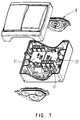
- FIGS 1 to 3 we see a box body 1 belonging to a sealed housing intended for accommodate the support 2 of the switch mechanism, and mainly comprising a wall bottom 3 and four side walls 4 to 7.
- This box body 1 is intended to be closed by a cover (not shown) after fixing the mechanism support in the housing.
- 5,7 of the side walls 4 to 7 of the housing, opposite one with respect to the other, are equipped each of a removable endpiece 8 intended to allow the leaktight crossing of a cable electrical 9 comprising the conductors 10 necessary for supplying the mechanism.
- This support 2 is present in the form of a substantially parallelepiped box, comprising on its face upper 2a, three screw terminals 11 intended to be connected to the aforementioned conductors 10. These three terminals 11 are aligned, which allows the conductors to be stripped to the same length.
- This support 2 further comprises, on one of its lateral faces 2b, two tabs 11a, 11b comprising returns 12 and intended to cooperate with sliding with two ribs 13 of complementary shape integral with the bottom 3 of the housing.
- fixing lugs 11a, 11b are intended to ensure the positioning of the mechanism in the housing and to absorb the forces when tightening the conductors 10 in the terminals 11 of the mechanism.
- the fixing of the mechanism on the bottom wall 3, in the vicinity of one 4 of the side walls having no end piece 8, is produced by means of an elastic tongue 14 forming clip extending parallel to the legs 11, and fixed approximately in the middle of its length on an outer face of one of the legs 11a.
- This tab 14 has, at one of its ends, a hook 15 capable of engaging in an opening 16 provided in the housing, when an elastic deformation of the tongue 14 is exerted by actuating a means grip 17 formed at the end of the tongue 14 opposite to that supporting the hook 15.
- the other 11b of the two legs has a zone 18 constituting a surface support for actuating the gripping means 17
- the mechanism 2 being fixed only on one side of the housing, the conductors 10 connected to the mechanisms and passing through one of the watertight bushings 8, can flow (FIG. 3) freely along the mechanism in the space e located between this mechanism and the wall 6 of the housing opposite to that 4 in the vicinity of which the fixing is carried out.
- the mechanism support 2 comprises a foot 19 intended to compensate for the tightening forces applied to the screws when connecting the conductors 10.
- This device can advantageously be used to fix mechanisms such as a switch, a push button, a back and forth or an electrical outlet. Attaching a plug current 20, as illustrated in Figure 6, in a housing according to the invention is illustrated in FIG. 5. The fastening elements being the same, these figures will not be not described again.
- each mechanism support will be provided with a projecting element forming a clip 23 and an opening 24, each projecting element 23 being able to engage in an opening 24 made in the mechanism support 22 which will be possibly juxtaposed.
- the same module for make single or double switches, which will be fixed in a standard box.
- the cables can pass either under or next to the mechanism, whereas in the case of a double switch, these cables will pass under the mechanisms.
- the support (s) can be separated from each other manually.
- the support (s) can also be detached from the housing manually, by user action on the two clips located laterally, the user is not bothered by the drivers.
Landscapes
- Engineering & Computer Science (AREA)
- Power Engineering (AREA)
- Switch Cases, Indication, And Locking (AREA)
Applications Claiming Priority (2)
| Application Number | Priority Date | Filing Date | Title |
|---|---|---|---|
| FR9715505 | 1997-12-02 | ||
| FR9715505A FR2771845B1 (fr) | 1997-12-02 | 1997-12-02 | Dispositif de fixation d'un mecanisme d'appareil electrique dans un boitier, support de mecanisme et boitier adaptes a un tel dispositif |
Publications (2)
| Publication Number | Publication Date |
|---|---|
| EP0921545A1 true EP0921545A1 (de) | 1999-06-09 |
| EP0921545B1 EP0921545B1 (de) | 2006-03-01 |
Family
ID=9514320
Family Applications (1)
| Application Number | Title | Priority Date | Filing Date |
|---|---|---|---|
| EP19980410136 Expired - Lifetime EP0921545B1 (de) | 1997-12-02 | 1998-12-01 | Vorrichtung zur Befestigung des Mechanismus eines elektrischen Gerätes in einem Gehäuse, Halterung für den Mechanismus und an solcher Vorrichtung angepasstes Gehäuse. |
Country Status (4)
| Country | Link |
|---|---|
| EP (1) | EP0921545B1 (de) |
| DE (1) | DE69833636T2 (de) |
| ES (1) | ES2259201T3 (de) |
| FR (1) | FR2771845B1 (de) |
Citations (5)
| Publication number | Priority date | Publication date | Assignee | Title |
|---|---|---|---|---|
| US2235382A (en) * | 1938-03-31 | 1941-03-18 | Westinghouse Electric & Mfg Co | Switch housing |
| US5272297A (en) * | 1992-11-23 | 1993-12-21 | General Electric Company | Streamlined air conditioning disconnect switch |
| EP0657905A1 (de) * | 1993-12-09 | 1995-06-14 | Legrand | Kassette zur Aufnahme elektrischer Komponenten in einem Gehäuse |
| EP0715382A1 (de) * | 1994-11-30 | 1996-06-05 | TEMIC TELEFUNKEN microelectronic GmbH | Vorrichtung zur Befestigung eines Gehäuses |
| EP0798834A1 (de) * | 1996-03-30 | 1997-10-01 | TEMIC TELEFUNKEN microelectronic GmbH | Gehäuse mit Mittel zur Befestigung auf einer Befestigungsplatte |
-
1997
- 1997-12-02 FR FR9715505A patent/FR2771845B1/fr not_active Expired - Fee Related
-
1998
- 1998-12-01 DE DE69833636T patent/DE69833636T2/de not_active Expired - Lifetime
- 1998-12-01 EP EP19980410136 patent/EP0921545B1/de not_active Expired - Lifetime
- 1998-12-01 ES ES98410136T patent/ES2259201T3/es not_active Expired - Lifetime
Patent Citations (5)
| Publication number | Priority date | Publication date | Assignee | Title |
|---|---|---|---|---|
| US2235382A (en) * | 1938-03-31 | 1941-03-18 | Westinghouse Electric & Mfg Co | Switch housing |
| US5272297A (en) * | 1992-11-23 | 1993-12-21 | General Electric Company | Streamlined air conditioning disconnect switch |
| EP0657905A1 (de) * | 1993-12-09 | 1995-06-14 | Legrand | Kassette zur Aufnahme elektrischer Komponenten in einem Gehäuse |
| EP0715382A1 (de) * | 1994-11-30 | 1996-06-05 | TEMIC TELEFUNKEN microelectronic GmbH | Vorrichtung zur Befestigung eines Gehäuses |
| EP0798834A1 (de) * | 1996-03-30 | 1997-10-01 | TEMIC TELEFUNKEN microelectronic GmbH | Gehäuse mit Mittel zur Befestigung auf einer Befestigungsplatte |
Also Published As
| Publication number | Publication date |
|---|---|
| FR2771845B1 (fr) | 2000-01-07 |
| FR2771845A1 (fr) | 1999-06-04 |
| DE69833636D1 (de) | 2006-04-27 |
| ES2259201T3 (es) | 2006-09-16 |
| EP0921545B1 (de) | 2006-03-01 |
| DE69833636T2 (de) | 2006-11-09 |
Similar Documents
| Publication | Publication Date | Title |
|---|---|---|
| FR2732518A1 (fr) | Agencement de connexion pour fils conducteurs electriques et module, notamment de type bloc de jonction, equipe d'un tel agencement | |
| EP1916743B1 (de) | Elektrisches Gerät, das mindestens eine Federanschlussklemme umfasst | |
| FR2524215A1 (fr) | Traversee a serre-cable | |
| EP0772256B1 (de) | Elektrisches Gerät mit Anschlussklemmen, die durch eine Blende mit Flügeln geschützt sind | |
| EP0683498B1 (de) | Modulares elektrisches Gerät mit Anschlussklemmen geschützt durch eine isolierende Platte | |
| FR2679405A1 (fr) | Reglette d'interconnexion, en particulier pour lignes telephoniques ou informatiques. | |
| EP0785606B1 (de) | Vorrichtung zum Befestigen eines elektrischen Gerätes | |
| FR2531577A1 (fr) | Contact electrique a pression a pouvoir de fermeture et d'ouverture incorpore | |
| FR2742918A1 (fr) | Dispositif de raccordement d'un conducteur exterieur tel un cable a une plage de contact d'un appareil electrique | |
| EP0896387B1 (de) | Schraubklemme und Anschlussleiste für einen elektrischen Apparat | |
| FR2514956A1 (fr) | Dispositif de connexion a enfichage | |
| EP0928043A1 (de) | Verbindungsvorrichtung mittels Käfigklemme | |
| FR2766628A1 (fr) | Peigne d'interconnexion pour alignement de bornes de raccordement electrique d'un appareillage et module(s) de logement d'appareillage correspondant(s) | |
| EP0921545B1 (de) | Vorrichtung zur Befestigung des Mechanismus eines elektrischen Gerätes in einem Gehäuse, Halterung für den Mechanismus und an solcher Vorrichtung angepasstes Gehäuse. | |
| FR2766297A1 (fr) | Appareil electrique portant un support de contact fixe et une borne de raccordement | |
| FR2837323A1 (fr) | Dispositif d'alimentation electrique | |
| WO1999065374A1 (fr) | Appareil electrique de cuisson a cuve amovible | |
| FR2577075A1 (fr) | Borne de connexion mixte pour circuit imprime et appareil electronique equipe d'une telle borne | |
| FR2699744A1 (fr) | Groupe boîte à bornes-câbles, en particulier pour l'alimentation électrique d'appareils électroménagers. | |
| EP1156551A1 (de) | Elektrisches Gerät mit elastischen Käfigklemmen | |
| EP0674357B1 (de) | Gehäuseteilen von elektrischen Verbindern | |
| EP1676349A1 (de) | Elektrische verbindungsschiene und angepasste verbindungseinrichtung | |
| FR2724493A1 (fr) | Ensemble de bornes a vis pour disjoncteur et disjoncteur muni d'un tel ensemble | |
| EP0806816A1 (de) | Verbindungszwischenanordnung für ein Energieübertragungsnetz und/oder zur Datenübertragung | |
| FR2461431A3 (fr) | Radiomicrophone a plusieurs emplois avec circuit imprime extractible |
Legal Events
| Date | Code | Title | Description |
|---|---|---|---|
| PUAI | Public reference made under article 153(3) epc to a published international application that has entered the european phase |
Free format text: ORIGINAL CODE: 0009012 |
|
| AK | Designated contracting states |
Kind code of ref document: A1 Designated state(s): BE CH DE ES IT LI |
|
| AX | Request for extension of the european patent |
Free format text: AL;LT;LV;MK;RO;SI |
|
| RAP1 | Party data changed (applicant data changed or rights of an application transferred) |
Owner name: SCHNEIDER ELECTRIC INDUSTRIES SA |
|
| 17P | Request for examination filed |
Effective date: 19991105 |
|
| AKX | Designation fees paid |
Free format text: BE CH DE ES IT LI |
|
| RAP1 | Party data changed (applicant data changed or rights of an application transferred) |
Owner name: SCHNEIDER ELECTRIC INDUSTRIES SA |
|
| RAP1 | Party data changed (applicant data changed or rights of an application transferred) |
Owner name: SCHNEIDER ELECTRIC INDUSTRIES SAS |
|
| 17Q | First examination report despatched |
Effective date: 20040812 |
|
| GRAP | Despatch of communication of intention to grant a patent |
Free format text: ORIGINAL CODE: EPIDOSNIGR1 |
|
| GRAS | Grant fee paid |
Free format text: ORIGINAL CODE: EPIDOSNIGR3 |
|
| GRAA | (expected) grant |
Free format text: ORIGINAL CODE: 0009210 |
|
| AK | Designated contracting states |
Kind code of ref document: B1 Designated state(s): BE CH DE ES IT LI |
|
| REG | Reference to a national code |
Ref country code: CH Ref legal event code: EP |
|
| REF | Corresponds to: |
Ref document number: 69833636 Country of ref document: DE Date of ref document: 20060427 Kind code of ref document: P |
|
| REG | Reference to a national code |
Ref country code: ES Ref legal event code: FG2A Ref document number: 2259201 Country of ref document: ES Kind code of ref document: T3 |
|
| PLBE | No opposition filed within time limit |
Free format text: ORIGINAL CODE: 0009261 |
|
| STAA | Information on the status of an ep patent application or granted ep patent |
Free format text: STATUS: NO OPPOSITION FILED WITHIN TIME LIMIT |
|
| 26N | No opposition filed |
Effective date: 20061204 |
|
| PGFP | Annual fee paid to national office [announced via postgrant information from national office to epo] |
Ref country code: DE Payment date: 20161209 Year of fee payment: 19 |
|
| PGFP | Annual fee paid to national office [announced via postgrant information from national office to epo] |
Ref country code: CH Payment date: 20171212 Year of fee payment: 20 Ref country code: BE Payment date: 20171024 Year of fee payment: 20 |
|
| PGFP | Annual fee paid to national office [announced via postgrant information from national office to epo] |
Ref country code: ES Payment date: 20180102 Year of fee payment: 20 |
|
| PGFP | Annual fee paid to national office [announced via postgrant information from national office to epo] |
Ref country code: IT Payment date: 20171221 Year of fee payment: 20 |
|
| REG | Reference to a national code |
Ref country code: DE Ref legal event code: R119 Ref document number: 69833636 Country of ref document: DE |
|
| PG25 | Lapsed in a contracting state [announced via postgrant information from national office to epo] |
Ref country code: DE Free format text: LAPSE BECAUSE OF NON-PAYMENT OF DUE FEES Effective date: 20180703 |
|
| REG | Reference to a national code |
Ref country code: CH Ref legal event code: PL |
|
| REG | Reference to a national code |
Ref country code: BE Ref legal event code: MK Effective date: 20181201 |
|
| REG | Reference to a national code |
Ref country code: ES Ref legal event code: FD2A Effective date: 20200724 |
|
| PG25 | Lapsed in a contracting state [announced via postgrant information from national office to epo] |
Ref country code: ES Free format text: LAPSE BECAUSE OF EXPIRATION OF PROTECTION Effective date: 20181202 |