EP0921545A1 - Dispositif de fixation d'un mécanisme d'appareil électrique dans un boitier, support de mécanisme et boitier adaptés à un tel dispositif - Google Patents
Dispositif de fixation d'un mécanisme d'appareil électrique dans un boitier, support de mécanisme et boitier adaptés à un tel dispositif Download PDFInfo
- Publication number
- EP0921545A1 EP0921545A1 EP98410136A EP98410136A EP0921545A1 EP 0921545 A1 EP0921545 A1 EP 0921545A1 EP 98410136 A EP98410136 A EP 98410136A EP 98410136 A EP98410136 A EP 98410136A EP 0921545 A1 EP0921545 A1 EP 0921545A1
- Authority
- EP
- European Patent Office
- Prior art keywords
- housing
- support
- fixing
- conductors
- hook
- Prior art date
- Legal status (The legal status is an assumption and is not a legal conclusion. Google has not performed a legal analysis and makes no representation as to the accuracy of the status listed.)
- Granted
Links
- 230000007246 mechanism Effects 0.000 title claims description 59
- 239000004020 conductor Substances 0.000 claims description 13
- 208000031968 Cadaver Diseases 0.000 description 2
- 230000000295 complement effect Effects 0.000 description 1
- 230000005489 elastic deformation Effects 0.000 description 1
- 238000007789 sealing Methods 0.000 description 1
Images

Classifications
-
- H—ELECTRICITY
- H01—ELECTRIC ELEMENTS
- H01H—ELECTRIC SWITCHES; RELAYS; SELECTORS; EMERGENCY PROTECTIVE DEVICES
- H01H9/00—Details of switching devices, not covered by groups H01H1/00 - H01H7/00
- H01H9/02—Bases, casings, or covers
-
- H—ELECTRICITY
- H02—GENERATION; CONVERSION OR DISTRIBUTION OF ELECTRIC POWER
- H02B—BOARDS, SUBSTATIONS OR SWITCHING ARRANGEMENTS FOR THE SUPPLY OR DISTRIBUTION OF ELECTRIC POWER
- H02B1/00—Frameworks, boards, panels, desks, casings; Details of substations or switching arrangements
- H02B1/26—Casings; Parts thereof or accessories therefor
- H02B1/46—Boxes; Parts thereof or accessories therefor
- H02B1/48—Mounting of devices therein
Definitions
- the invention relates to a device for fixing the mechanism of an electrical appliance such as a switch or socket in a box, a mechanism support intended to be fixed by means of this device, as well as a housing adapted to such a fixing device.
- housings mainly consist of a box body and a cover, said body box comprising a bottom wall and four side walls. Two of the side walls, located opposite to each other, include means for passing the conductors intended to be connected to the mechanism.
- a case is described for example in patent document FR 2 716 752.
- the mechanism bases are fixed in the housing at two points located respectively in the vicinity of two opposite side walls of the housing. The result that the mechanism takes up the entire width of the housing, and therefore that the housing has reduced wiring space.
- the present invention solves these problems and proposes a device for fixing a mechanism in a housing offering increased wiring space so as to facilitate passage of conductors and their connection, a mechanism base adapted to this device, as well as a housing allowing the fixing of such a mechanism.
- the present invention relates to a device of the kind previously mentioned, this device being characterized in that it comprises fixing means provided partly on the mechanism and partly on the housing and providing a fixing of the mechanism on one side of the housing, in the vicinity of one of the side walls or on this side wall, so as to free a passage for the conductors between said mechanism and the side wall of the housing opposite to the previous one.
- the invention also relates to a mechanism support capable of being fixed in a housing by means of the aforementioned device and a housing adapted to receive such a support.
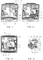
- FIGS 1 to 3 we see a box body 1 belonging to a sealed housing intended for accommodate the support 2 of the switch mechanism, and mainly comprising a wall bottom 3 and four side walls 4 to 7.
- This box body 1 is intended to be closed by a cover (not shown) after fixing the mechanism support in the housing.
- 5,7 of the side walls 4 to 7 of the housing, opposite one with respect to the other, are equipped each of a removable endpiece 8 intended to allow the leaktight crossing of a cable electrical 9 comprising the conductors 10 necessary for supplying the mechanism.
- This support 2 is present in the form of a substantially parallelepiped box, comprising on its face upper 2a, three screw terminals 11 intended to be connected to the aforementioned conductors 10. These three terminals 11 are aligned, which allows the conductors to be stripped to the same length.
- This support 2 further comprises, on one of its lateral faces 2b, two tabs 11a, 11b comprising returns 12 and intended to cooperate with sliding with two ribs 13 of complementary shape integral with the bottom 3 of the housing.
- fixing lugs 11a, 11b are intended to ensure the positioning of the mechanism in the housing and to absorb the forces when tightening the conductors 10 in the terminals 11 of the mechanism.
- the fixing of the mechanism on the bottom wall 3, in the vicinity of one 4 of the side walls having no end piece 8, is produced by means of an elastic tongue 14 forming clip extending parallel to the legs 11, and fixed approximately in the middle of its length on an outer face of one of the legs 11a.
- This tab 14 has, at one of its ends, a hook 15 capable of engaging in an opening 16 provided in the housing, when an elastic deformation of the tongue 14 is exerted by actuating a means grip 17 formed at the end of the tongue 14 opposite to that supporting the hook 15.
- the other 11b of the two legs has a zone 18 constituting a surface support for actuating the gripping means 17
- the mechanism 2 being fixed only on one side of the housing, the conductors 10 connected to the mechanisms and passing through one of the watertight bushings 8, can flow (FIG. 3) freely along the mechanism in the space e located between this mechanism and the wall 6 of the housing opposite to that 4 in the vicinity of which the fixing is carried out.
- the mechanism support 2 comprises a foot 19 intended to compensate for the tightening forces applied to the screws when connecting the conductors 10.
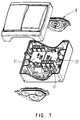
- This device can advantageously be used to fix mechanisms such as a switch, a push button, a back and forth or an electrical outlet. Attaching a plug current 20, as illustrated in Figure 6, in a housing according to the invention is illustrated in FIG. 5. The fastening elements being the same, these figures will not be not described again.
- each mechanism support will be provided with a projecting element forming a clip 23 and an opening 24, each projecting element 23 being able to engage in an opening 24 made in the mechanism support 22 which will be possibly juxtaposed.
- the same module for make single or double switches, which will be fixed in a standard box.
- the cables can pass either under or next to the mechanism, whereas in the case of a double switch, these cables will pass under the mechanisms.
- the support (s) can be separated from each other manually.
- the support (s) can also be detached from the housing manually, by user action on the two clips located laterally, the user is not bothered by the drivers.
Landscapes
- Engineering & Computer Science (AREA)
- Power Engineering (AREA)
- Switch Cases, Indication, And Locking (AREA)
Abstract
Description
- la figure 1 est une vue en perspective, illustrant le corps de boíte d'un boítier dans lequel le mécanisme d'un interrupteur est destiné à être fixé au moyen du dispositif de l'invention,
- la figure 2 est une vue identique à la précédente illustrant le mécanisme fixé dans le boítier,
- la figure 3 est une vue de dessus du corps de boíte logeant le mécanisme et illustrant le passage des conducteurs,
- la figure 4 est une vue en perspective du mécanisme seul,
- la figure 5 est une vue similaire à la figure 2, le mécanisme d'interrupteur étant remplacé par un mécanisme de prise de courant,
- la figure 6 est une vue en perspective du mécanisme de prise de courant seul, et
- la figure 7 est une vue en perspective éclatée illustrant un interrupteur double.
Claims (14)
- Dispositif de fixation du support de mécanisme d'un appareil électrique tel un interrupteur dans un boítier, ledit boítier comprenant un corps de boíte et un couvercle, le corps de boíte comprenant une paroi de fond et quatre parois latérales, caractérisé en ce qu'il comporte des moyens de fixation prévus en partie sur le support de mécanisme (2) et en partie sur l'une des parois latérales du boítier et réalisant une fixation du mécanisme sur un seul côté du boítier, de manière à libérer un passage (e) pour les conducteurs (10) entre ledit mécanisme (2) et la paroi latérale (6) du boítier (1) opposée à la précédente.
- Dispositif selon la revendication 1, caractérisé en ce que deux (5,7) des parois latérales du boítier, opposées l'une par rapport à l'autre, comportant chacune une traversée (8) de conducteurs (10), le mécanisme (2) est fixé sur ou au voisinage d'une paroi latérale (4,6) ne comportant pas de traversée.
- Dispositif selon la revendication 1 ou 2, caractérisé en ce que les moyens de fixation précités comprennent un crochet (15) formé à l'extrémité d'une languette (14) élastique solidaire du support du mécanisme (2), ledit crochet (15) coopérant avec une ouverture (16) prévue dans le boítier (1) pour réaliser l'encliquetage du mécanisme (2) sur le boítier.
- Dispositif selon la revendication 3, caractérisé en ce que la languette (14) comporte à son extrémité opposée au crochet (15) un élément de préhension (17) apte à déformer la languette (14) de manière à libérer le crochet (15) de l'ouverture (16) du boítier.
- Dispositif selon l'une quelconque des revendications 1 à 4, caractérisé en ce que le support du mécanisme (2) comporte au moins une patte (11a, 11b) apte à coopérer avec au moins une nervure (13) du boítier de manière à réaliser le positionnement du mécanisme dans le boítier.
- Dispositif selon la revendication 5, caractérisé en ce que les pattes précitées (11a, 11b) comportent des retours (2) aptes à coulisser sur les nervures précitées (13).
- Dispositif selon les revendications 4 et 5, caractérisé en ce que les pattes (11a, 11b) sont au nombre de deux, et en ce que sur l'une (11a) des pattes est fixée la languette (14), au voisinage du milieu de sa longueur, l'autre patte (11b) comportant une zone (18) constituant une surface d'appui pour l'actionnement du moyen de préhension (17).
- Dispositif selon l'une quelconque des revendications précédentes, caractérisé en ce que le support de mécanisme (2) comporte un pied (19) destiné à compenser les efforts de serrage appliqués aux vis lors du raccordement des conducteurs (10).
- Support de mécanisme d'un appareil électrique, caractérisé en ce qu'il est adapté pour être fixé sur un boítier (1) au moyen d'un dispositif selon l'une quelconque des revendications 1 à 8.
- Support de mécanisme selon la revendication 9, caractérisé en ce que c'est un mécanisme d'interrupteur, de prise de courant, de poussoir ou de va et vient.
- Support de mécanisme selon la revendication 9 ou 10, caractérisé en ce qu'il comporte des bornes (11) alignées de manière à permettre le dénudage des fils à une même longueur.
- Support de mécanisme selon l'une quelconque des revendications 9 à 11, caractérisé en ce qu'il comporte un clip (23) et une ouverture (24) agencés de manière à permettre l'engagement du clip (23) de l'un des supports (21) dans l'ouverture (24) appartenant à un autre support (22) juxtaposé au premier dans un même boítier (1).
- Boítier pour un mécanisme d'appareil électrique, caractérisé en ce qu'il est adapté pour la fixation d'un mécanisme au moyen d'un dispositif selon l'une quelconque des revendications 1 à 8.
- Boitier selon la revendication 13, caractérisé en ce qu'il comporte, du côté du boítier opposé à celui de la fixation du support du mécanisme précité (21), des moyens de fixation d'un second support de mécanisme (22) identique au premier mais disposé tête bêche par rapport au premier (21).
Applications Claiming Priority (2)
| Application Number | Priority Date | Filing Date | Title |
|---|---|---|---|
| FR9715505A FR2771845B1 (fr) | 1997-12-02 | 1997-12-02 | Dispositif de fixation d'un mecanisme d'appareil electrique dans un boitier, support de mecanisme et boitier adaptes a un tel dispositif |
| FR9715505 | 1997-12-02 |
Publications (2)
| Publication Number | Publication Date |
|---|---|
| EP0921545A1 true EP0921545A1 (fr) | 1999-06-09 |
| EP0921545B1 EP0921545B1 (fr) | 2006-03-01 |
Family
ID=9514320
Family Applications (1)
| Application Number | Title | Priority Date | Filing Date |
|---|---|---|---|
| EP19980410136 Expired - Lifetime EP0921545B1 (fr) | 1997-12-02 | 1998-12-01 | Dispositif de fixation d'un mécanisme d'appareil électrique dans un boitier, support de mécanisme et boitier adaptés à un tel dispositif |
Country Status (4)
| Country | Link |
|---|---|
| EP (1) | EP0921545B1 (fr) |
| DE (1) | DE69833636T2 (fr) |
| ES (1) | ES2259201T3 (fr) |
| FR (1) | FR2771845B1 (fr) |
Citations (5)
| Publication number | Priority date | Publication date | Assignee | Title |
|---|---|---|---|---|
| US2235382A (en) * | 1938-03-31 | 1941-03-18 | Westinghouse Electric & Mfg Co | Switch housing |
| US5272297A (en) * | 1992-11-23 | 1993-12-21 | General Electric Company | Streamlined air conditioning disconnect switch |
| EP0657905A1 (fr) * | 1993-12-09 | 1995-06-14 | Legrand | Cassette pour le logement d'un composant électrique dans un boîtier |
| EP0715382A1 (fr) * | 1994-11-30 | 1996-06-05 | TEMIC TELEFUNKEN microelectronic GmbH | Dispositif pour fixer un boîtier |
| EP0798834A1 (fr) * | 1996-03-30 | 1997-10-01 | TEMIC TELEFUNKEN microelectronic GmbH | Boîte avec un dispositif d'attachement à une platine de montage |
-
1997
- 1997-12-02 FR FR9715505A patent/FR2771845B1/fr not_active Expired - Fee Related
-
1998
- 1998-12-01 DE DE69833636T patent/DE69833636T2/de not_active Expired - Lifetime
- 1998-12-01 ES ES98410136T patent/ES2259201T3/es not_active Expired - Lifetime
- 1998-12-01 EP EP19980410136 patent/EP0921545B1/fr not_active Expired - Lifetime
Patent Citations (5)
| Publication number | Priority date | Publication date | Assignee | Title |
|---|---|---|---|---|
| US2235382A (en) * | 1938-03-31 | 1941-03-18 | Westinghouse Electric & Mfg Co | Switch housing |
| US5272297A (en) * | 1992-11-23 | 1993-12-21 | General Electric Company | Streamlined air conditioning disconnect switch |
| EP0657905A1 (fr) * | 1993-12-09 | 1995-06-14 | Legrand | Cassette pour le logement d'un composant électrique dans un boîtier |
| EP0715382A1 (fr) * | 1994-11-30 | 1996-06-05 | TEMIC TELEFUNKEN microelectronic GmbH | Dispositif pour fixer un boîtier |
| EP0798834A1 (fr) * | 1996-03-30 | 1997-10-01 | TEMIC TELEFUNKEN microelectronic GmbH | Boîte avec un dispositif d'attachement à une platine de montage |
Also Published As
| Publication number | Publication date |
|---|---|
| DE69833636T2 (de) | 2006-11-09 |
| EP0921545B1 (fr) | 2006-03-01 |
| FR2771845B1 (fr) | 2000-01-07 |
| FR2771845A1 (fr) | 1999-06-04 |
| ES2259201T3 (es) | 2006-09-16 |
| DE69833636D1 (de) | 2006-04-27 |
Similar Documents
| Publication | Publication Date | Title |
|---|---|---|
| FR2580432A1 (fr) | Connecteur de liaison pour conducteurs electriques | |
| FR2732518A1 (fr) | Agencement de connexion pour fils conducteurs electriques et module, notamment de type bloc de jonction, equipe d'un tel agencement | |
| EP1916743B1 (fr) | Appareil électrique comprenant au moins une borne de raccordement à ressort | |
| FR2524215A1 (fr) | Traversee a serre-cable | |
| EP0772256B1 (fr) | Appareil électrique à bornes de raccordement protégées par un diaphragme à fixation par des ailes | |
| EP0683498B1 (fr) | Appareil électrique modulaire à bornes de raccordement protégées par une plaquette isolante | |
| EP0785606B1 (fr) | Dispositif de fixation d'un appareil électrique | |
| EP0524115A1 (fr) | Réglette d'interconnexion, en particulier pour lignes téléphoniques ou informatiques | |
| FR2531577A1 (fr) | Contact electrique a pression a pouvoir de fermeture et d'ouverture incorpore | |
| EP0896387B1 (fr) | Borne à vis et bornier pour appareil électrique. | |
| FR2514956A1 (fr) | Dispositif de connexion a enfichage | |
| EP0928043A1 (fr) | Dispositif de connexion à cage élastique | |
| FR2766628A1 (fr) | Peigne d'interconnexion pour alignement de bornes de raccordement electrique d'un appareillage et module(s) de logement d'appareillage correspondant(s) | |
| EP0921545B1 (fr) | Dispositif de fixation d'un mécanisme d'appareil électrique dans un boitier, support de mécanisme et boitier adaptés à un tel dispositif | |
| FR2766297A1 (fr) | Appareil electrique portant un support de contact fixe et une borne de raccordement | |
| FR2837323A1 (fr) | Dispositif d'alimentation electrique | |
| WO1999065374A1 (fr) | Appareil electrique de cuisson a cuve amovible | |
| FR2577075A1 (fr) | Borne de connexion mixte pour circuit imprime et appareil electronique equipe d'une telle borne | |
| FR2699744A1 (fr) | Groupe boîte à bornes-câbles, en particulier pour l'alimentation électrique d'appareils électroménagers. | |
| EP1156551A1 (fr) | Appareil électrique à bornes dotées de cages élastiques | |
| EP0674357B1 (fr) | Eléments de boítier d'un connecteur électrique | |
| EP1676349A1 (fr) | Barre de raccordement electrique et dispositif de connexion adapte | |
| FR2724493A1 (fr) | Ensemble de bornes a vis pour disjoncteur et disjoncteur muni d'un tel ensemble | |
| EP0806816A1 (fr) | Dispositif intermédiaire de raccordement pour un réseau de transport d'énergie électrique et/ou de transfert de données | |
| FR2461431A3 (fr) | Radiomicrophone a plusieurs emplois avec circuit imprime extractible |
Legal Events
| Date | Code | Title | Description |
|---|---|---|---|
| PUAI | Public reference made under article 153(3) epc to a published international application that has entered the european phase |
Free format text: ORIGINAL CODE: 0009012 |
|
| AK | Designated contracting states |
Kind code of ref document: A1 Designated state(s): BE CH DE ES IT LI |
|
| AX | Request for extension of the european patent |
Free format text: AL;LT;LV;MK;RO;SI |
|
| RAP1 | Party data changed (applicant data changed or rights of an application transferred) |
Owner name: SCHNEIDER ELECTRIC INDUSTRIES SA |
|
| 17P | Request for examination filed |
Effective date: 19991105 |
|
| AKX | Designation fees paid |
Free format text: BE CH DE ES IT LI |
|
| RAP1 | Party data changed (applicant data changed or rights of an application transferred) |
Owner name: SCHNEIDER ELECTRIC INDUSTRIES SA |
|
| RAP1 | Party data changed (applicant data changed or rights of an application transferred) |
Owner name: SCHNEIDER ELECTRIC INDUSTRIES SAS |
|
| 17Q | First examination report despatched |
Effective date: 20040812 |
|
| GRAP | Despatch of communication of intention to grant a patent |
Free format text: ORIGINAL CODE: EPIDOSNIGR1 |
|
| GRAS | Grant fee paid |
Free format text: ORIGINAL CODE: EPIDOSNIGR3 |
|
| GRAA | (expected) grant |
Free format text: ORIGINAL CODE: 0009210 |
|
| AK | Designated contracting states |
Kind code of ref document: B1 Designated state(s): BE CH DE ES IT LI |
|
| REG | Reference to a national code |
Ref country code: CH Ref legal event code: EP |
|
| REF | Corresponds to: |
Ref document number: 69833636 Country of ref document: DE Date of ref document: 20060427 Kind code of ref document: P |
|
| REG | Reference to a national code |
Ref country code: ES Ref legal event code: FG2A Ref document number: 2259201 Country of ref document: ES Kind code of ref document: T3 |
|
| PLBE | No opposition filed within time limit |
Free format text: ORIGINAL CODE: 0009261 |
|
| STAA | Information on the status of an ep patent application or granted ep patent |
Free format text: STATUS: NO OPPOSITION FILED WITHIN TIME LIMIT |
|
| 26N | No opposition filed |
Effective date: 20061204 |
|
| PGFP | Annual fee paid to national office [announced via postgrant information from national office to epo] |
Ref country code: DE Payment date: 20161209 Year of fee payment: 19 |
|
| PGFP | Annual fee paid to national office [announced via postgrant information from national office to epo] |
Ref country code: CH Payment date: 20171212 Year of fee payment: 20 Ref country code: BE Payment date: 20171024 Year of fee payment: 20 |
|
| PGFP | Annual fee paid to national office [announced via postgrant information from national office to epo] |
Ref country code: ES Payment date: 20180102 Year of fee payment: 20 |
|
| PGFP | Annual fee paid to national office [announced via postgrant information from national office to epo] |
Ref country code: IT Payment date: 20171221 Year of fee payment: 20 |
|
| REG | Reference to a national code |
Ref country code: DE Ref legal event code: R119 Ref document number: 69833636 Country of ref document: DE |
|
| PG25 | Lapsed in a contracting state [announced via postgrant information from national office to epo] |
Ref country code: DE Free format text: LAPSE BECAUSE OF NON-PAYMENT OF DUE FEES Effective date: 20180703 |
|
| REG | Reference to a national code |
Ref country code: CH Ref legal event code: PL |
|
| REG | Reference to a national code |
Ref country code: BE Ref legal event code: MK Effective date: 20181201 |
|
| REG | Reference to a national code |
Ref country code: ES Ref legal event code: FD2A Effective date: 20200724 |
|
| PG25 | Lapsed in a contracting state [announced via postgrant information from national office to epo] |
Ref country code: ES Free format text: LAPSE BECAUSE OF EXPIRATION OF PROTECTION Effective date: 20181202 |