EP0922191B1 - Wärmetauscher für luft mit trockener oberfläche - Google Patents
Wärmetauscher für luft mit trockener oberfläche Download PDFInfo
- Publication number
- EP0922191B1 EP0922191B1 EP97938661A EP97938661A EP0922191B1 EP 0922191 B1 EP0922191 B1 EP 0922191B1 EP 97938661 A EP97938661 A EP 97938661A EP 97938661 A EP97938661 A EP 97938661A EP 0922191 B1 EP0922191 B1 EP 0922191B1
- Authority
- EP
- European Patent Office
- Prior art keywords
- air
- liquid
- heat transfer
- dry
- heat exchanger
- Prior art date
- Legal status (The legal status is an assumption and is not a legal conclusion. Google has not performed a legal analysis and makes no representation as to the accuracy of the status listed.)
- Expired - Lifetime
Links
- 238000012546 transfer Methods 0.000 claims abstract description 157
- 239000007788 liquid Substances 0.000 claims abstract description 142
- 238000001816 cooling Methods 0.000 claims abstract description 73
- 239000000463 material Substances 0.000 claims abstract description 13
- 229920003002 synthetic resin Polymers 0.000 claims abstract description 13
- 239000000057 synthetic resin Substances 0.000 claims abstract description 13
- 238000007789 sealing Methods 0.000 claims abstract description 5
- 239000003570 air Substances 0.000 claims description 137
- 125000006850 spacer group Chemical class 0.000 claims description 62
- 238000009826 distribution Methods 0.000 claims description 19
- 239000012080 ambient air Substances 0.000 claims description 8
- 230000000694 effects Effects 0.000 claims description 5
- 230000015572 biosynthetic process Effects 0.000 claims description 4
- 230000008093 supporting effect Effects 0.000 claims description 3
- 210000003141 lower extremity Anatomy 0.000 claims description 2
- 230000004308 accommodation Effects 0.000 claims 1
- 239000012530 fluid Substances 0.000 abstract description 9
- XLYOFNOQVPJJNP-UHFFFAOYSA-N water Substances O XLYOFNOQVPJJNP-UHFFFAOYSA-N 0.000 description 141
- 238000010276 construction Methods 0.000 description 53
- 238000002156 mixing Methods 0.000 description 12
- 238000013461 design Methods 0.000 description 10
- 241000282326 Felis catus Species 0.000 description 8
- 230000008901 benefit Effects 0.000 description 7
- 230000000670 limiting effect Effects 0.000 description 4
- 239000000243 solution Substances 0.000 description 4
- 239000000853 adhesive Substances 0.000 description 3
- 230000001070 adhesive effect Effects 0.000 description 3
- 230000005465 channeling Effects 0.000 description 3
- 229920000915 polyvinyl chloride Polymers 0.000 description 3
- 239000004800 polyvinyl chloride Substances 0.000 description 3
- 229920006395 saturated elastomer Polymers 0.000 description 3
- LYCAIKOWRPUZTN-UHFFFAOYSA-N Ethylene glycol Chemical compound OCCO LYCAIKOWRPUZTN-UHFFFAOYSA-N 0.000 description 2
- 230000002411 adverse Effects 0.000 description 2
- WYTGDNHDOZPMIW-RCBQFDQVSA-N alstonine Natural products C1=CC2=C3C=CC=CC3=NC2=C2N1C[C@H]1[C@H](C)OC=C(C(=O)OC)[C@H]1C2 WYTGDNHDOZPMIW-RCBQFDQVSA-N 0.000 description 2
- 230000001976 improved effect Effects 0.000 description 2
- 230000006872 improvement Effects 0.000 description 2
- 230000001965 increasing effect Effects 0.000 description 2
- 238000009434 installation Methods 0.000 description 2
- 230000001788 irregular Effects 0.000 description 2
- 238000004519 manufacturing process Methods 0.000 description 2
- 238000005192 partition Methods 0.000 description 2
- 238000005086 pumping Methods 0.000 description 2
- 230000002829 reductive effect Effects 0.000 description 2
- 239000004676 acrylonitrile butadiene styrene Substances 0.000 description 1
- 239000012267 brine Substances 0.000 description 1
- 230000008859 change Effects 0.000 description 1
- 230000001010 compromised effect Effects 0.000 description 1
- 230000001419 dependent effect Effects 0.000 description 1
- 238000011161 development Methods 0.000 description 1
- 238000011156 evaluation Methods 0.000 description 1
- 210000003414 extremity Anatomy 0.000 description 1
- 230000002349 favourable effect Effects 0.000 description 1
- WGCNASOHLSPBMP-UHFFFAOYSA-N hydroxyacetaldehyde Natural products OCC=O WGCNASOHLSPBMP-UHFFFAOYSA-N 0.000 description 1
- 230000001939 inductive effect Effects 0.000 description 1
- 230000000977 initiatory effect Effects 0.000 description 1
- 230000002452 interceptive effect Effects 0.000 description 1
- 230000007246 mechanism Effects 0.000 description 1
- 239000002184 metal Substances 0.000 description 1
- 238000000034 method Methods 0.000 description 1
- 238000000465 moulding Methods 0.000 description 1
- 230000036961 partial effect Effects 0.000 description 1
- 230000035515 penetration Effects 0.000 description 1
- 230000008569 process Effects 0.000 description 1
- 230000000284 resting effect Effects 0.000 description 1
- 238000012552 review Methods 0.000 description 1
- HPALAKNZSZLMCH-UHFFFAOYSA-M sodium;chloride;hydrate Chemical compound O.[Na+].[Cl-] HPALAKNZSZLMCH-UHFFFAOYSA-M 0.000 description 1
- 239000002352 surface water Substances 0.000 description 1
- 239000011800 void material Substances 0.000 description 1
- 238000003466 welding Methods 0.000 description 1
Images





Classifications
-
- F—MECHANICAL ENGINEERING; LIGHTING; HEATING; WEAPONS; BLASTING
- F28—HEAT EXCHANGE IN GENERAL
- F28F—DETAILS OF HEAT-EXCHANGE AND HEAT-TRANSFER APPARATUS, OF GENERAL APPLICATION
- F28F25/00—Component parts of trickle coolers
- F28F25/02—Component parts of trickle coolers for distributing, circulating, and accumulating liquid
-
- F—MECHANICAL ENGINEERING; LIGHTING; HEATING; WEAPONS; BLASTING
- F28—HEAT EXCHANGE IN GENERAL
- F28C—HEAT-EXCHANGE APPARATUS, NOT PROVIDED FOR IN ANOTHER SUBCLASS, IN WHICH THE HEAT-EXCHANGE MEDIA COME INTO DIRECT CONTACT WITHOUT CHEMICAL INTERACTION
- F28C1/00—Direct-contact trickle coolers, e.g. cooling towers
- F28C1/14—Direct-contact trickle coolers, e.g. cooling towers comprising also a non-direct contact heat exchange
-
- F—MECHANICAL ENGINEERING; LIGHTING; HEATING; WEAPONS; BLASTING
- F28—HEAT EXCHANGE IN GENERAL
- F28F—DETAILS OF HEAT-EXCHANGE AND HEAT-TRANSFER APPARATUS, OF GENERAL APPLICATION
- F28F25/00—Component parts of trickle coolers
- F28F25/02—Component parts of trickle coolers for distributing, circulating, and accumulating liquid
- F28F25/08—Splashing boards or grids, e.g. for converting liquid sprays into liquid films; Elements or beds for increasing the area of the contact surface
- F28F25/087—Vertical or inclined sheets; Supports or spacers
-
- Y—GENERAL TAGGING OF NEW TECHNOLOGICAL DEVELOPMENTS; GENERAL TAGGING OF CROSS-SECTIONAL TECHNOLOGIES SPANNING OVER SEVERAL SECTIONS OF THE IPC; TECHNICAL SUBJECTS COVERED BY FORMER USPC CROSS-REFERENCE ART COLLECTIONS [XRACs] AND DIGESTS
- Y02—TECHNOLOGIES OR APPLICATIONS FOR MITIGATION OR ADAPTATION AGAINST CLIMATE CHANGE
- Y02B—CLIMATE CHANGE MITIGATION TECHNOLOGIES RELATED TO BUILDINGS, e.g. HOUSING, HOUSE APPLIANCES OR RELATED END-USER APPLICATIONS
- Y02B30/00—Energy efficient heating, ventilation or air conditioning [HVAC]
- Y02B30/70—Efficient control or regulation technologies, e.g. for control of refrigerant flow, motor or heating
-
- Y—GENERAL TAGGING OF NEW TECHNOLOGICAL DEVELOPMENTS; GENERAL TAGGING OF CROSS-SECTIONAL TECHNOLOGIES SPANNING OVER SEVERAL SECTIONS OF THE IPC; TECHNICAL SUBJECTS COVERED BY FORMER USPC CROSS-REFERENCE ART COLLECTIONS [XRACs] AND DIGESTS
- Y10—TECHNICAL SUBJECTS COVERED BY FORMER USPC
- Y10S—TECHNICAL SUBJECTS COVERED BY FORMER USPC CROSS-REFERENCE ART COLLECTIONS [XRACs] AND DIGESTS
- Y10S165/00—Heat exchange
- Y10S165/90—Cooling towers
-
- Y—GENERAL TAGGING OF NEW TECHNOLOGICAL DEVELOPMENTS; GENERAL TAGGING OF CROSS-SECTIONAL TECHNOLOGIES SPANNING OVER SEVERAL SECTIONS OF THE IPC; TECHNICAL SUBJECTS COVERED BY FORMER USPC CROSS-REFERENCE ART COLLECTIONS [XRACs] AND DIGESTS
- Y10—TECHNICAL SUBJECTS COVERED BY FORMER USPC
- Y10S—TECHNICAL SUBJECTS COVERED BY FORMER USPC CROSS-REFERENCE ART COLLECTIONS [XRACs] AND DIGESTS
- Y10S261/00—Gas and liquid contact apparatus
- Y10S261/11—Cooling towers
Definitions
- the present invention relates generally to air-cooled, dry-heat exchangers, and more particularly to an assembly for use as a part of an air-cooled, atmospheric water cooling tower for cooling a liquid with currents of air.
- wet evaporative heat exchangers presents siting problems because of the necessity or desirability of limiting formation of a visible discharge or plume oftentimes encountered with large conventional evaporative or wet-type water cooling towers.
- the use of dry towers also offers the advantage of limiting the loss of liquid as a result of the evaporative effect.
- dry towers allow cooling of fluids other than water, which would preclude the use of an evaporative tower. Fog or plume abatement and the concomitant advantages of dry heat exchange have led to proposals that the dry concept be employed in larger industrial-sized towers, and that evaporative fill and air-cooled heat exchangers be incorporated into a single tower.
- a wet surface water cooling tower having a selectively usable dry surface heat exchanger unit as an integral part thereof may be locatable in closer proximity to a roadway than would otherwise be the case because of the plume abatement afforded by the added dry section. Without adequate plume abatement, location of a wet cooling tower in proximity to a roadway could result in obstructed visibility hazards which would preclude such positioning of the tower.
- an air-cooled atmospheric heat exchanger is illustrated as including a plurality of U-shaped members arranged in a pack, wherein each member is preformed out of a low cost synthetic resin material such as polyvinyl chloride.
- Each U-shaped member presents a pair of side-by-side panels that are connected together by a common, longitudinally extending upper edge, and the panels of each member present front and rear, vertically extending side edges that are sealed to the side edges of the panels on adjacent members in the pack.
- each panel presents a wet-transfer surface adapted to transfer heat between the water and the panel, and a dry-transfer surface adapted to transfer heat between the panel and air passing through the pack.
- the '689 patent teaches that air can be intentionally entrained in the hot water entering the top of the pack to slow the travel of the water through the heat exchanger and preclude the build-up of negative pressures between the panels of adjacent members.
- the negative pressures that built up between the sheet sections defining the upright water passages were so great that the sheet sections collapsed toward one another thus creating restrictions in downward flow of water and limiting the overall efficiency of the equipment.
- the patentee in the '689 patent sought to eliminate leaking of water from the water passages defined by the pack sheets by causing air to be entrained in the water entering the water passages.
- this was found to be only partially satisfactory, and the problem was exacerbated by difficulties in effectively sealing the interengaging edges of the sheets, particularly at the air inlet face of the patent.
- EP 0 464 875 also discloses a heat exchanger for a cooling tower.
- the heat exchanger is formed by assembling a plurality of heat exchanging partition plates formed by moulding, which have the same shape and the same dimensions, and which are easily engageable with and detachable from each other.
- Each adjacent two heat exchanging partition plates constitute a single heat exchanger unit and liquid-flowing passages are formed between adjacent heat exchanger units.
- the present invention provides a dry-air-surface heat exchanger for cooling of a liquid with air currents, comprising:
- the present invention further provides a wet-dry atmospheric cooling tower for cooling a liquid with currents of air without the formation of a significant visible plume, said cooling tower comprising:
- the present invention further provides heat exchange pack comprising:
- An atmospheric water cooling tower for cooling a liquid with currents of air may be is provided with a dry-air surface heat exchanger according to the invention and formed of individual members, each including a pair of panels that are folded together along a vertical axis and sealed along the side edges thereof to present a vertical water flow passage between the panels and a pair of outer, horizontally extending air flow passages across the outside surfaces of the panels.
- the heat exchanger for use as a part of an atmospheric water cooling tower includes a plurality of the members, arranged in a pack, and a support means for supporting the members side-by-side, with the surfaces of the folded members oriented parallel to one another.
- a diffuser is provided adjacent the upper edges of the folded members for receiving hot water and directing the hot water between the panels of each folded member.
- the diffuser means is constructed and arranged to seat against the upper edges of the folded members to block air from being entrained in the water that is introduced between the panels of each member.
- Collection means is also provided for collecting cooled water exiting from between the panels.
- such a heat exchanger having heat exchange members formed of synthetic resin material and including spacers for maintaining a predetermined spacing between panels and for restricting the panels from being disfigured during use attributable to negative pressure that might build-up in the water flow passages between the panels is provided.
- a dry-air-surface heat exchanger for use as a part of an atmospheric water cooling tower and having relatively open, unobstructed air passages between adjacent members, minimizing pressure drop between the front and rear edges of the heat exchanger and increasing efficiency relative to conventional constructions is provided.
- the heat exchanger of the present invention preferably includes a preformed, shape-retaining heat transfer member of relatively thin synthetic resin sheet material presenting a pair of upright,side-by-side panels, vertically extending side edges, horizontally extending upper and lower edges, a wet-transfer surface adapted to transfer heat between the water and the member, and a dry-transfer surface adapted to transfer heat between the member and air.
- the member is preferably folded about a vertical axis, with the wet-transfer surfaces in facing relationship so that the vertical axis defines a front edge of the heat exchanger.
- the folded member is preferably configured to present a series of tortuous water flow paths between the panels extending between the upper and lower edges, and the side edges are secured together in substantially fluid tight sealing engagement.
- heat exchange member constructed in accordance with the present invention, numerous advantages are realized. For example, by forming the member with a pair of upright, side-by-side panels, it is possible to fold the member and seal the edges together to obtain a substantially leak proof water flow passage between the upper and lower edges of the panel. In addition, it is possible to employ spacers for maintaining the spacing between the panels within the water flow passage without interfering with the passage of air horizontally across the outer surfaces of the panels. The spacers prevent the panels from being disfigured by negative pressures within the water flow passage, reducing channeling and improving the efficiency of the heat exchanger.
- the liquid passages of the dry-air-surface heat exchanger are preferably of dimensions such that the center-to-center spacing between the panels of each tubular heat transfer member is from about 0.0254 m to about 0.0381 m (about I to about 1.5 inches) and the ratio of the liquid space volume of the combination of the total volume of the air passages and the liquid passages is from about 0.35 to about 0.6.
- This critical relationship was surprisingly found to provide an optimum balance between hydraulic operation and efficient transfer of heat in the water to the cooling air currents directed through the heat exchanger at an economical overall water cooling tower cost.
- a particularly important aspect of this invention is its utility as a dry-air-surface heat exchanger to be used without significant change in a water cooling tower where plume abatement is a requirement, in a cooling tower installation where water conservation is the primary goal, or as a stand-alone unit as a substitute for a finned tube heat exchanger.
- the diffuser is constructed in a manner to seal the upper water inlets of the side-by-side panel members, thus preventing water from entering the air passages therebetween.
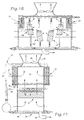
- a combination wet section counterflow and dry section cross-flow atmospheric mechanical draft cooling tower is shown schematically in Fig. 17, and broadly includes a hot water distribution assembly 22, a cold water collection assembly 24 and a central, mechanically powered fan 26 circumscribed by an upright, venturi-shaped stack 28 positioned atop the tower on an apertured fan deck for inducing ambient derived air currents through the tower.
- a central plenum 30 is defined between respective opposed units of the heat exchanger apparatus of the tower.
- the apparatus may be annular in shape, or provided in separate, opposed rectangular sections as illustrated.
- the walls of the tower are provided with apertures into which ambient air is drawn by the fan 26, and the air passes through the heat exchanger apparatus into the central plenum 30 before passing out of the tower past the fan.
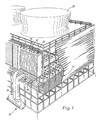
- the heat exchanger apparatus is illustrated in Fig. 1, and includes upper, dry-air-surface heat exchanger units 32 constructed in accordance with the preferred embodiment, and lower, conventional evaporative wet fill units 34.
- the hot water distribution assembly includes a first set of distribution lines 36 for distributing hot water to the upper units for cooling, and a second set of distribution lines 38 for distributing hot water directly to the lower fill units.
- the second set of lines also includes collection lines 40 for collecting cooled water from the upper units so that water exiting the upper units can be directed into the lower fill units 34 for further cooling.
- Nozzles 42 or the like are provided for evenly distributing water over the upper and lower units to obtain uniform cooling of the water passing through the units.
- the cold water collection assembly is shown in Fig. 17, and includes a base 44 underlying the lower fill units, and a return line 46 for removing cooled water from the tower.
- the dry-air-surface heat exchanger units 32 are generally identical to one another, and one of the units is illustrated in Fig. 2.
- the unit includes a plurality of individual, discrete, tubular members 48 supported in an upright, side-by-side orientation within a pack, a diffuser 50 for receiving hot water from the hot water distribution assembly and directing the hot water into the pack, for gravitational flow downwardly through respective members 48, and a collection basin 52 for collecting cooled water exiting the pack.
- Each of the tubular members 48 has a generally horizontal, elongated liquid inlet at the upper end thereof and a corresponding, generally horizontal, elongated liquid outlet at the lower extremity of the tubular member in substantial vertical alignment with the liquid inlet thereabove.
- a series of the tubular members 48 are provided in side-by-side relationship presenting the pack thereof with the elongated side margins of the liquid inlets in proximal, side-by side, substantially abutting relationship.
- a frame 54 supports the collection basin 52, diffuser 50 and pack, and includes a pair of front-to-rear beams 56 underlying the collection basin, a pair of upstanding side walls 58 enclosing the sides of the pack, and a plurality of support tubes 60 extending through the pack between the side walls 58.
- the front side of the frame is open, defining an air inlet into which ambient air is drawn.
- the rear side of the frame is also open and defines an air outlet of the unit. As such, the front side of the frame is exposed to an opening in the tower while the rear side of the unit opens into the central plenum 30, as shown in Fig. 17.
- the collection basin 52 is supported on the beams 56 and defines an open reservoir beneath the pack into which cooled water falls from the members 48.
- a drain is provided in the basin and is connected through the collection lines 40 (Fig. 17) to the hot water distribution lines for introduction into the lower fill units, as shown in Fig. 1. Alternately, the drain can be connected directly to the water collection assembly where the dry-air-surface heat exchanger units are to be used exclusively, independent of the lower fill units.
- Each individual member 48 forming a part of the pack is substantially identical to every other member, and is preformed from a shape-retaining, relatively thin synthetic resin sheet material such as polyvinyl chloride or the like.
- the preformed sheet of each member 48 is generally rectangular in shape, and is divided by a central, longitudinal axis 62 into two side-by-side panels 64, 66.
- a center margin 68 including the longitudinal axis separates the panels from one another and extends between upper and lower edges of the sheet.
- Marginal side edges 74, 76 also extend between the upper and lower edges.
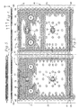
- a dry-transfer surface of the sheet is shown in Fig. 3, and is adapted to transfer heat from the member to air passing over and contacting the surface.
- the opposing surface of the sheet is complemental in shape to the dry-transfer surface, and serves as a wet-transfer surface for transferring heat from hot water to the member as the water passes over and contacts the surface during use.
- Each panel also presents a corrugated chevron or zigzag pattern 78 formed therein between the upper and lower edges of the sheet.
- the pattern 78 defines a plurality of side-by-side, normally vertically extending serpentine water flow paths in the wet-transfer surface.
- the corrugated chevron or zigzag pattern 78 is made up of a series of grooves which are defined by peaks and valleys, defining a groove transversely thereof.
- the grooves are of V-shaped configuration in the plane of each panel with the V's alternately opening toward opposed side edges of the sheet 64.
- the maximum vertical extent of each oppositely opening V groove may be defined as the height of that groove.
- the included angle of each of the oppositely opening V grooves is preferably the same for all of such grooves.
- a regular pattern of protrusions 80 is formed in each panel, wherein each protrusion is of truncated conical shape and protrudes from the wet-transfer surface of the panel, terminating in a generally planar end surface adapted to engage a similarly oriented spacer on the opposing panel when the member has been folded about the vertical axis 62.
- the protrusions 80 are uniformly spaced from one another over the area of the panel and each serves to define a spacing means for maintaining a predetermined space between the wet-transfer surfaces of the panels to prevent the panels from caving in toward one another during use when a negative pressure occurs within the member.
- the panel 64 includes a plurality of identically configured, vertically spaced nesting elements 82 that are formed in the sheet at the time of manufacture.
- Each nesting element 82 is generally oval in shape, defining a longitudinal axis extending in a direction perpendicular to the upper and lower edges of the sheet.
- each element protrudes from the wet-transfer surface of the panel and presents an elongated ridge 84 along the longitudinal axis.
- the ridge is interrupted by a pair of vertically spaced transverse recesses 86.
- a pair of laterally spaced projections 88 are provided on each nesting element 82, wherein the projections are disposed on opposite sides of the ridge 84 and protrude from the dry-transfer surface of the panel 64.
- Each projection 88 is oval in shape, presenting a central, longitudinally extending ridge that extends in a direction parallel to the longitudinal axis of the element 82.
- the panel 66 also includes a plurality of identically configured, vertically spaced nesting elements 90 that are formed in the sheet at the time of manufacture.
- Each nesting element 90 is generally oval in shape, defining a longitudinal axis extending in a direction parallel to the upper and lower edges of the sheet.
- each element protrudes from the dry-transfer surface of the panel and presents an elongated ridge 92 along the longitudinal axis.
- the ridge is interrupted by a pair of horizontally spaced vertically extending recesses 94.
- a pair of vertically spaced projections 96 are provided on each nesting element, wherein the projections are disposed on opposite sides of the ridge and protrude from the wet-transfer surface of the panel.
- Each projection is oval in shape, presenting a ridge that extends in a direction parallel to the longitudinal axis of the element 90.
- the elements 82 are aligned with the elements 90 so that when the member is folded about the vertical axis 62, the ridges of the projections 96 on the panel 66 engage the recesses 86 in the ridges 84 of the elements 82, positioning the panels 64,66 relative to one another while maintaining a space between the wet-transfer surfaces thereof.
- the nesting elements 82, 90 cooperate with the protrusions 80 to define the spacing means.
- this provision includes the formation of a plurality of circular, generally planar areas 98 in each panel, wherein each area may be cut from the sheet in order to receive one of the support tubes.
- the opening areas 98 in the two panels are oriented such that, upon folding of the member about vertical axis 62, the openings in each panel align with the openings in the other panel.
- each opening area in the panel 64 is surrounded by a tubular, preferably annular, ridged margin 100 that protrudes from the dry-transfer surface of the sheet, and each opening area in the panel 66 is surrounded by an annular ridged margin 102 that protrudes from the wet-transfer surface of the sheet.
- the annular margins 100, 102 formed in the two panels of each member nest against one another when the member is folded about the vertical axis and can be sealed shut with a suitable adhesive to substantially block air and water from leaking into or out of the water flow passage defined by the member.
- the center margin 68 of the sheet is planar, being void of the chevron or zigzag pattern that dominates the panels 64, 66.
- a plurality of vertically aligned inlet spacers 104 are formed in the sheet along the margin beside each panel.
- Each spacer 104 protrudes from the dry-transfer surface of the sheet and is generally teardrop-shaped, defining a longitudinal axis that extends horizontally in a direction parallel to the upper and lower edges 70, 72.
- the teardrop shape of each spacer tapers horizontally away from the vertical axis 62 so that when the member is folded about the axis, defining the front edge of the member, the spacers present an aerodynamic profile to the air stream passing horizontally over the dry-transfer surfaces of the panels.
- the inlet spacers 104 on each side of the vertical axis are aligned with the spacers on the opposite side of the axis so that when the member is folded and assembled in the pack, the inlet spacers of adjacent members engage one another to maintain a space between the members through which air travels during use of the heat exchanger.
- outlet spacers 106 are formed in the sheet along the side edges 74, 76 thereof, wherein each row includes a plurality of vertically spaced outlet spacers that protrude from the dry-transfer surface of the sheet.
- Each outlet spacer 106 is generally oval-shaped, defining a longitudinal axis that is angled relative to the upper and lower edges of the sheet by an angle of about 20°-35°.
- outlet spacers on each edge are aligned with the spacers on the opposite edge so that when the member is folded and assembled in the pack, the outlet spacers of adjacent members engage one another to maintain a space between the members through which air travels during use of the heat exchanger.
- spacers 106 they are strategically configured to direct air flow thereover upwardly toward the air outlet plenum and discharge stack or stacks of the tower
- Each panel 64, 66 of the member 48 is preformed to present a horizontally extending ridge 108 along the upper edge of the sheet that protrudes from the dry-transfer surface thereof.
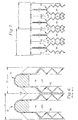
- the ridges of the panels are aligned with one another so that when the member is folded about the vertical axis 62, an enlarged opening is defined between the wet-transfer surfaces of the panels, as shown in Fig. 5.
- Each ridge is formed with a horizontally extending groove 110, as shown in Fig. 3, that protrudes inwardly of the folded member, as shown in Fig. 5.
- the grooves apply pressure to the diffuser, as described below, so that hot water is directed between the panels and air is substantially blocked from being entrained in the water.
- each sheet can be formed with more than one repeating, horizontally extending ridge 108 so that a single design of the sheet can be used in towers of at least two or more different heights.
- a second ridge 108 is formed beneath the upper ridge and provides a line 111 along which the material can be cut in order to shorten the height of the member formed from the sheet. If the full length of the sheet is employed in constructing a member, the intermediate ridge 108 forms a part of the member and serves to space adjacent members within the pack from one another.
- each member 48 is folded along the vertical axis 62, as shown in Fig. 4, with the wet-transfer surfaces of the panels in facing relationship, and the outermost marginal side edges 74, 76 sealed together with an adhesive.
- the annular margins 100, 102 surrounding the opening areas are also adhesively sealed together.
- the protrusions 80 on the panel 64 engage the protrusions of the panel 66, as shown in Fig. 5, spacing the wet-transfer surfaces from one another to define a water flow passage extending from the upper edge of the folded member to the lower edge thereof.
- the nesting elements 82, 90 of the two panels nest against one another in the manner described above and orient the panels upon folding of the member, and also serve to maintain the space between the wet-transfer surfaces during use.
- the chevron or zigzag pattern 78 in the panel 64 opposes the pattern formed in the panel 66, and is preferably designed so that each channel defined in the wet-transfer surface of the panel 64 extends in a direction opposite to the direction in which the opposing channel of the panel 66 extends.
- a plurality of the folded members 48 are assembled on the support tubes 60 to form the pack of the heat exchanger, and the opening areas 98 of each member are cut out from the member in order to accommodate the support tubes.
- the pack is assembled by positioning a plurality of the members on the support tubes in side-by-side relation to one another.
- the nesting elements 90 on each member protrude from the dry-transfer surface of the panel 66 and engage the projections 88 of the nesting elements 82 in the panel 64 of the adjacent member so that the projections 88 nest in the recesses 94 to properly orient the members relative to one another and maintain a spacing between adjacent members through which ambient air is drawn during use of the heat exchanger.
- the inlet spacers 104 and outlet spacers 106 of each member engage the inlet and outlet spacers of adjacent members in the pack to establish and maintain the spacing between the members.
- the nesting elements 82, 90, the inlet spacers 104, and the outlet spacers 106 cooperate to maintain the air flow passages between the members.
- the aerodynamic profile of the inlet and outlet spacers 104, 106 serves to minimize the air pressure drop across the pack during use.
- the nesting elements 90 that protrude from the dry-transfer surface of each member are horizontally oriented so that they also present an aerodynamic profile that reduces the pressure drop of air passing through the pack. Because the nesting elements 82 protrude from the wet-transfer surface of each member, they do not impede air flow through the air passageways.
- the liquid delivered to the water inlets of the tubular members 48 of the cooling tower illustrated herein is essentially at atmospheric pressure (typically no more than about 3 to 4 milibars difference from atmospheric pressure).
- the cold water collection basin is open to the atmosphere.
- the mechanical draft tower hereof also is desirably provided with air moving means of characteristics such as to cause the velocity of the air currents passing through the pack of tubular members 48 to be from about 200 to about 1,000 feet per minute.
- the horizontal transverse space, "X" occupied by each of the members 48 should be from about 1 inch to about 1.5 inches, desirably from about 1.1 inches to about 1.3 inches, and preferably about 1.2 inches.
- the efficiency of the pack in transferring heat between hot liquid flowing through the liquid passages to air being drawn through the pack horizontally is maximized.
- the heat exchanger construction employs members 112 presenting much larger air flow passages 114 than water flow passages 116.
- the water flow passages of each pack presented only about 30% of the pack volume while the air flow passages presented approximately 70% of the pack volume.
- the unique diffuser 50 of the invention as illustrated in Figs. 8-10 is preferably formed of a synthetic resin material such as acrylonitrile-butadiene-styrene (ABS) or the like.
- the diffuser includes a bottom wall 118 that is surrounded by upstanding side walls 120 such that a chamber 122 is defined within which hot water can be distributed from the nozzles of the hot water distribution assembly.
- the bottom wall is divided into three laterally extending, longitudinally spaced rows of troughs 124 that depend from the bottom wall.
- each row is aligned with troughs in the other rows so that a line of three troughs are presented to each member 48 of the pack.
- a slot 126 is formed in each trough prior to assembly in the heat exchanger such that the diffuser provides a means for delivering water from the chamber 122 to the interior spaces of the members of the pack.
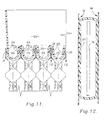
- the grooves 110 (Fig. 11) formed along the upper edges of the panels 64, 66 of each member protrude from the wet-transfer surfaces of the panels and engage the three troughs 124 disposed between the panels to substantially block air and water from migrating out of their respective passages. It is to be noted that the general complemental engagement of the troughs 124 with the underlying water entrance passages of respective member 48 serves to substantially prevent ingress of air into the liquid inlets at the upper end of each member 48.
- diffusers 50 as illustrated and described are provided in the preferred embodiment of the invention, such diffusers are not essential so long as equivalent means is provided for delivering water or liquid to be cooled into the open uppermost inlets of the tubular members while at the same time preventing undesirable ingress of significant quantities of air into respective tubular liquid passages.
- the construction of tubular members 48 facilitates side-by-side positioning thereof with the horizontal inlet openings at the top of each liquid passage of the members 48 in horizontally aligned, interengaging relationship.
- the proximal edges of the members 48 may be sealed if desired with an adhesive or by ultrasonic welding.
- the construction and arrangement of tubular members 48 is such that gasket and upright wall seals may readily be provided across opposite upper ends of the pack of tubular members 48.
- This vertical wall resting on an appropriate gasket construction at each upper water inlet and upper air outlet edges of the pack can readily be located at the generally Y-shaped end extremities of each of the tubular members 48, as depicted in Fig. 5.
- the wall and gasket construction would extend across the entire side-to-side width of the pack at the front and rear thereof, thus excluding entrance of air into the liquid passages of tubular members 48.
- the troughs of the diffuser can be adhesively sealed to the members along the upper edges of the members to further block air from migrating into the water passages and water from migrating into the air passages. It is noteworthy that the grooves defining the chevron pattern of panels 64 serve to very quickly, evenly distribute liquid to be cooled across the entire width of each water passage. In the exchanger of the prior art '689 patent, the vertical stiffening ribs 40 of each panel were adhesively interconnected thus defining a series of individual tubular upright water passages.
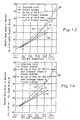
- Fig. 13 is a graphical representation illustrating a psychometric analysis of the plume abatement capabilities of an air-cooled heat exchanger constructed in accordance with the present invention as compared with the corresponding capabilities of two conventional finned tube heat exchanger constructions.
- the chart expresses the condition of the air passing through each of the heat exchanger constructions in terms of the humidity ratio, or grains of moisture per 0.454 kg (per pound) of dry air, there being 7,000 grains of moisture per 0.454 kg (pound) of moisture.
- the chart expresses the temperature of the air as the dry bulb temperature, expressed in degrees centigrade.
- the curve 128 represents the temperature at which air is saturated with moisture and extends from the lower left-hand comer of the chart to the upper right-hand corner thereof.
- the capabilities of a first conventional air-cooled heat exchanger construction are shown as an irregular dashed line 130 terminating at a triangle and being spaced vertically above the saturation curve 128 along a substantial portion of the length thereof.
- the first conventional construction represents a finned tube design having a cost of about equal to that of the preferred embodiment of this invention.
- the capabilities of a second conventional air-cooled heat exchanger construction are shown as a regular dashed line 132 terminating at a circle and being tangent with the saturation curve 128.
- the second conventional construction represents a finned tube design having a width twice that of the first conventional construction and a cost about twice that of the preferred embodiment of the invention.
- an air-cooled heat exchanger construction in accordance with the preferred embodiment is shown as a solid line 134 in the chart, terminating at a square. The entire length of the line 134 is below the saturation curve 128.
- the chart of Fig. 13 illustrates the effectiveness of the preferred embodiment of the invention in abating or eliminating the development of fog or plumes during use of the heat exchanger.
- the lines representative of the two conventional finned tube constructions contact or rise above the saturation curve, the air passing through those constructions reaches a super-saturated condition at which the moisture in the air condenses, forming visible, unwanted plumes. Operation of a tower in accordance with conditions as indicated by the line 130 of chart 13 would result in a substantial plume.
- Fig. 14 is a graphical representation similar to Fig. 13, analyzing the plume abatement capabilities of an air-cooled heat exchanger constructed in accordance with the present invention as compared with the capabilities of two conventional air-cooled heat exchangers constructed in accordance with the '689 patent.
- the chart expresses the condition of the air passing through each of the heat exchanger constructions in terms of the humidity ratio, and the temperature of the air as the dry bulb temperature, expressed in degrees Fahrenheit.
- the curve 128 in Fig. 14 again represents the temperature at which air is saturated and extends from the lower lefthand corner of the chart to the upper right-hand comer thereof.
- the capabilities of a first conventional air-cooled heat exchanger construction as represented by the construction of the '689 Cates patent are shown as an irregular dashed line 131 terminating at a triangle and being spaced vertically above the saturation curve 128 along a substantial portion of the length thereof.
- This first conventional construction includes a volume that is 1.5 times that of the preferred embodiment of this invention.
- the capabilities of a second conventional air-cooled heat exchanger unit constructed in accordance with the '689 patent are shown as a regular dashed line 133 terminating at a circle and being in contact with the saturation curve 128 along a portion of the length thereof.
- the second conventional construction has a volume 3.75 times greater than that of the preferred embodiment of this invention.
- an air-cooled heat exchanger construction in accordance with the preferred embodiment is shown as a solid line 134 in Fig. 14, terminating at a square.
- the entire length of the line 134 is below the saturation curve 128, demonstrating again the improved plume abatement provided by the construction of the preferred embodiment.
- the improvement obtained through the use of the present invention goes beyond that which might be expected based on a comparison of the surface area presented by each of the constructions compared in the chart.
- the unexpected improvement in the plume abatement capabilities of the preferred construction result at least partially from the reduced air pressure drop across the construction as compared with that across the conventional constructions.
- This lower pressure drop permits more air to pass through the air-cooled heat exchanger unit of the preferred embodiment, providing a two-fold advantage in cooling towers combining conventional fill units and air-cooled heat transfer units constructed in accordance with the preferred embodiment; less evaporative heat transfer is required which means less moisture is introduced into the wet section air stream of the cooling tower; and more dry heat is available from the dry air stream to abate the plume.
- Fig. 15 is a graphical representation illustrating the water cooling capability of an air-cooled heat exchanger constructed in accordance with the present invention as compared with that of a conventional air-cooled heat exchanger construction of comparable cost at a hot water temperature of 48,9°C (120°F).
- Fig. 16 is a graphical representation similar to Fig. 15, illustrating the water cooling capabilities of the air-cooled heat exchangers at a hot water temperature of 32,2°C (90°F).
- the left-hand margin of each graph represents the temperature of the water exiting the heat exchangers subsequent to cooling, expressed in degrees celcius (Fahrenheit).
- the bottom margin of each graph represents the dry bulb temperature of the ambient air used to cool the water, expressed in degrees celcius (Fahrenheit).
- the lower line 136 in each graph represents the results achieved by the heat exchanger constructed in accordance with the preferred embodiment of the invention while the upper line 138 in each graph represents the results achieved by a conventional metal finned tube construction of comparable cost.
- the heat exchanger constructed in accordance with the preferred embodiment hereby provides greater cooling of the water than the referenced conventional construction of comparable cost. Accordingly, a designer of a water cooling tower has more options when employing the inventive construction and can either add more heat exchanger units for the same cost as a conventional finned tube design in order to obtain improved results, or achieve the same performance at a reduced cost.
- Fig. 17 is a schematic representation of a mechanical draft crossflow cooling tower employing separate air-cooled heat exchangers in combination with conventional evaporative fill units similar to that shown in Fig. 1.
- Fig. 18 is a schematic representation of a mechanical draft cooling tower employing separate air-cooled crossflow heat exchanger units 32 in combination with conventional crossflow evaporative fill units 140, wherein the air-cooled heat exchanger units 32 are located above and outside of the fill units 140, 142, and some of the fill units 142 are used to cool water that is discharged from the air-cooled units 32.
- Such a construction facilitates the use of the fill units 140 independently of the air-cooled units to accommodate varying cooling loads and requirements.
- Fig. 19 is a schematic representation of a mechanical draft crossflow cooling tower employing separate air-cooled heat exchanger units 32 positioned atop conventional evaporative fill units 144. Thus, water discharged from the air-cooled units 32 is fed directly into the fill units 144, eliminating the need for additional distribution lines between the air-cooled units and the fill units.
- Fig. 20 is a schematic representation of another mechanical draft crossflow cooling tower employing separate air-cooled heat exchanger units 32 positioned above conventional, angled evaporative fill units 146.
- Fig. 21 is a schematic representation of a mechanical draft crossflow cooling tower employing a separate air-cooled heat exchanger unit 32 on one side thereof and a conventional, angled evaporative fill unit 146 on the other side thereof.
- the units may be used either simultaneously or independently in order to handle varying cooling requirements under differing ambient conditions.
- Fig. 22 is a fragmentary schematic representation of a mechanical draft crossflow cooling tower as shown in Fig. 20, illustrating outer air dampers 148 provided at the inlet side of the upper and/or lower heat exchanger units.
- Optional inner air dampers can be provided at the outlet side of the upper and lower heat exchanger units, as shown by the phantom lines 150. Such dampers permit additional control over the flow of air through the units to improve operation of the units under varying ambient conditions and water loads.
- the mechanical draft plume abatement water cooling tower illustrated in Fig. 23 and designated by the numeral 200 has two opposed upper, air-cooled heat exchanger units 232, lower, conventional, counter-flow evaporative wet fill units 234, and air stream mixing baffle structure generally designated as 250.
- the structure 250 may advantageously take the form of a plurality of individual baffles 252 which extend into the plenum area 230 above wet fill units 234. As is apparent from Fig.
- baffles 252 may serve the required purpose of effecting an intimate mixing of the moist and dry air within plenum 230 for ultimate discharge through stack 228, with one baffle 252a extending from the heat exchanger unit 232a to the central part of plenum 230, while opposed baffles 252b project from heat exchanger unit 232b toward the center of the plenum 230. It is notable from Fig. 23 that baffle 252a is aligned with the space between baffles 252b.
- baffles as represented by 252a and 252b may in certain instances be adequate for mixing the moist and dry air in the plenum of a small single cell cooling tower, it is to be understood that the number and relative orientation of the baffles may be changed as desirable or necessary to assure adequate intermixing of the moist and dry air.
- the cooling tower depicted in Fig. 23 is intended to be representative only and illustrative of baffling which may be used if required to enhance mixing of the moist and dry air streams emanating from the heat exchanger units 232 and wet fill units 234 respectively within plenum 230.
- the baffles 252 are provided to promote blending of the respective moist and dry air masses into a common, more homogenous air mass before being discharged into the atmosphere through the upper end of stack 228. Wet air, if not sufficiently mixed with dry air before being discharged, may form visible vapor until it mixes sufficiently into the atmosphere. As an example of an application where plume abatement is critical, water cooling towers adjacent the runways of an airport require that no plume be emitted from the tower which would interfere with runway visibility under varying ambient weather conditions. Less critical applications may not require mixing baffles 252 provided that some modest amount of visible plume is acceptable.
- baffles 252 are omitted from the wet-dry cooling tower, air streams exiting from the air-cooled heat exchangers 232 and lower wet fill units 234 have a natural propensity to follow segregated paths as a consequence of their geometric orientations. Air streams from the air-cooled units 232 tend to follow a direct path to the nearest respective lower edges of stack 228. surprisingly little air stream mixing occurs at fan 226. Baffles 252 serve to interrupt air streams exiting from lower fill units 234 and allow penetration of the dry air streams from the upper air-cooled units 232 into the central part of plenum 230. It is to be understood in this respect that although not specifically depicted in schematic drawings Figs. 18 and 20-22, mixing baffles such as structure 250 may be employed in such constructions if necessary or desirable to assure adequate mixing of the moist and dry air streams in the plenum of the tower.
- the dry-air-surface heat exchangers 32 of this invention should be constructed to conform to a number of critical parameters.
- the maximum cross-sectional width of each of the members 48 i.e., the distance from a vertical plane through the outermost faces of the protrusions 80 extending outwardly from one main corrugated surface of each member 48 to a vertical plane through the outermost faces of the protrusions 80 projecting outwardly from the other main corrugated surface of each member 48 (the distance designated "X" in Fig.
- 7) should be from about 0,0254 m (1 inch) to about 0,0381 m (1.5 inches), desirably from about 0,0279 m (1.1 inches) to about 0,0330 m (1.3 inches), and preferably about (0,0305 m (1.2 inches).
- from about 8 to 12 of the members 48 should be provided per horizontal lineal foot of the pack of members making up a respective dry-air-surface heat exchanger 32, desirably about 9 to 11 members 48 per horizontal 0.305 m (linear foot) of the heat exchanger pack, and preferably about 10 members 48 per horizontal 0.305 m (per linear foot).
- the ratio of the total vertical, cross-sectional area of the liquid passages through the members 48 making up a pack of a respective heat exchanger unit 32 with respect to the total vertical, cross-sectional area of the air passages between members 48 of that pack should be from about 0.67 to about 1.5.
- the center-to-center spacing between the panels of each tubular heat transfer member i.e., a value equal to the center of each liquid passage to the center of an adjacent liquid passage (dimension "X" in Fig. 7), is from about 0.0254m (1 in) to about 0.0381m (1.5 in).
- the ratio of the liquid space volume of the liquid passages with respect to the total volume of the combination of the air passages and the liquid passages being from about 0.35 to about 0.6.
- the air passage to water passage volume ratios should be from about 40% air passages to about 60% water passages, desirably from about 50% air passages to about 50% water passages, and preferably about 60% air passages to about 40% water passages.
- the depth of the grooves making up the serpentine, chevron pattern 78 of the main panel sections of members 48 should range from about 0.003m (0.1 inch) to about 0,010 m (0,4 inch), most desirably from about 0,005 m (0.19 inch) to about 0,008 m (0.325 inch), and preferably be about 0,007m (0.26 inch).
- each of the V-shaped grooves 78 which alternately face toward opposite side margins of each member 48, i.e., the maximum distance between each wall segment of a V-shaped groove away from the apex thereof, should be from about 0,0305 m (1.2 inches) to about 0,0508 m (2 inches)and preferably about 0,0457m (1.8 inches).
- the included angle of each V-shaped groove should be from about 40° to about 70° and preferably about 60° horizontal angles.
- the spacing of the members as represented by the distance "Y" of Fig. 6, is 0,0635m (2.5 inches) representing 4.8 of the dry surface members per horizontal 0,305 m (lineal foot) of the heat exchanger pack.
- the ratio of the dry surface heat exchanger area of this invention is over twice as much as the surface area of the dry surface heat exchanger of the '689 patent. Consequently, in order to obtain heat exchange performance from the structure of the '689 patent equivalent to that of the present invention, the cost of such construction would be from about 1.8 to about 2.5 times more costly.
- Superior heat transfer capability is an important advantage of the present invention over the tower of the Cates patent and conventional finned coil-type construction.
- finned coil wet-dry cooling towers configured for plume abatement, it is the usual practice to direct all of the water to be cooled in serial order through the finned coil dry heat exchange section and the evaporative heat exchange section, with a single pumping stage being employed to elevate the hot water to be cooled to the upper end of the overlying finned coil dry exchange section.
- a substantial part of the extra energy consumed in pumping the entire volume of hot water to be cooled to the top of the dry fin coil section of the tower can be recovered in certain instances by taking advantageous of the syphon loop that is created in the closed dry section circuit.
- the dry heat exchange section would be so inefficient that 100% of the hot water to be cooled also would have to be pumped through the dry section before being distributed over the wet heat exchange section. Again, the entire volume of hot water to be cooled would have to be pumped to the upper end of the cooling tower at the top of the dry heat exchange section. However, in this instance, none of the additional pump head energy required to pump all of the hot water to the top of the dry exchange section could be recovered because the upper end of the dry section of Cates is vented into the atmosphere and there is no suction loop created.
- this invention allows a design election to be made, i.e., to use separate pumps to supply hot water to be cooled to the dry heat exchanger units 32 and to the evaporative heat exchanger units 34, thus significantly limiting the amount of water that must be pumped to the dry heat exchanger relative to the total water flow to the tower.
- the dry heat exchanger units 32 are at a substantially higher elevation than the evaporative heat exchanger units 34, the less hot water that must be pumped to that higher elevation the better, not only from the standpoint of size of pump requirements, but also because of higher operating costs for a larger pump.
- Pump heads are often energy evaluated on large cooling tower installations for economic comparisons of altemative designs by as much as $100,000 per 0,305 m (foot) of head, or more.
- Fluids other than water may be cooled.
- Illustrative in this respect are glycol solutions or brine solutions.
- the temperature of the fluid to be cooled should not exceed about 82.2°C (180°F) in instances where the members 48 are fabricated of a synthetic resin such as polyvinyl chloride or the like.
Landscapes
- Engineering & Computer Science (AREA)
- Mechanical Engineering (AREA)
- General Engineering & Computer Science (AREA)
- Physics & Mathematics (AREA)
- Thermal Sciences (AREA)
- Heat-Exchange Devices With Radiators And Conduit Assemblies (AREA)
- Fuel Cell (AREA)
- Drying Of Gases (AREA)
Claims (69)
- Luft-Wärmetauscher (32) mit trockener Oberfläche zum Kühlen einer Flüssigkeit mit Luftströmen, wobei der Wärmetauscher Folgendes umfasst:dadurch gekennzeichnet, dass das Verhältnis zwischen dem gesamten vertikalen Querschnittsbereich der Flüssigkeitskanäle durch die Wärmeübertragungselemente (48) beim Gebrauch und dem gesamten vertikalen Querschnittsbereich der Luftkanäle zwischen den Wärmeübertragungselementen (48) etwa 1:0,67 bis etwa 1:1,5 beträgt und das Flüssigkeitsverteilungsmittel zum Zuführen von zu kühlender Flüssigkeit in jeweilige Wärmeübertragungselemente (48) durch deren Flüssigkeitseinlässe dient, während ein Eindringen von Luft in die Flüssigkeitseinlässe zu den Flüssigkeitskanälen im Wesentlichen verhindert wird.ein Wärmetauscheraggregat mit einer Mehrzahl von diskreten, röhrenförmigen Wärmeübertragungselementen (48) aus Kunstharzplattenmaterial, wobei jedes der genannten Wärmeübertragungselemente (48) zwei Seite an Seite angeordnete Tafeln mit entgegengesetzten, ineinander eingreifenden Vorder- und Hinterkanten (74, 76) hat, wobei beabstandete Oberkanten einen Flüssigkeitseinlass dazwischen definieren, beabstandete Unterkanten einen Flüssigkeitsauslass dazwischen definieren und Haupttafelabschnitte in beabstandeter Beziehung einen Flüssigkeitskanal dazwischen definieren und mit gegenüberliegenden Flächen versehen sind, wobei die Seite an Seite angeordneten Tafeln und die Vorder- und Hinterkanten beim Gebrauch aufrecht stehen, wobei die Oberkanten und die Unterkanten beim Gebrauch allgemein horizontal verlaufen und die Haupttafelabschnitte beim Gebrauch in horizontal beabstandeter Beziehung sind, wobei die Vorder- und Hinterkanten (74, 76) der Haupttafelabschnitte ausreichend ineinander eingreifen, um einen signifikanten Ausfluss von Flüssigkeit aus dem jeweiligen Flüssigkeitskanal zu verhindern, wobei die Wärmeübertragungselemente (48) in Nebeneinanderlagebeziehung sind, so dass Luftkanäle dazwischen entstehen;Flüssigkeitsverteilungsmittel zum Zurühren von zu kühlender Flüssigkeit in jeweilige Wärmeübertragungselemente (48) durch deren Flüssigkeitseinlässe; undMittel zum Sammeln von gekühlter Flüssigkeit, die von den Flüssigkeitsauslässen der Wärmeübertragungselemente zugeführt wurde,
- Luft-Wärmetauscher (32) mit trockener Oberfläche nach Anspruch 1, wobei jedes der Wärmeübertragungselemente (48) eine geformte Kunstharzplatte umfasst, die entlang einer Linie (62) gefaltet wurde, so dass die einander gegenüberliegenden, Seite an Seite angeordneten Tafeln (64, 66) entstehen.
- Luft-Wärmetauscher (32) mit trockener Oberfläche nach Anspruch 1 oder 2, ferner umfassend eine Reihe von Abstandshaltern (80) zum Halten eines Abstands zwischen den einander gegenüberliegenden Oberflächen der Tafeln (64, 66), um zu verhindern, dass die Tafelabschnitte beim Gebrauch zusammen kommen.
- Luft-Wärmetauscher (32) mit trockener Oberfläche nach Anspruch 3, wobei die Abstandshalter (80) eine Mehrzahl von vorgeformten, formhaltenden Abstandshalterelementen aufweisen, die von den einander gegenüberliegenden Flächen jedes Tafelabschnitts aufeinander zu vorstehen,
wobei die Abstandshalterelemente so gestaltet sind, dass sie an jedem Tafelabschnitt positioniert werden, um in ein entsprechendes Abstandshalterelement am gegenüberliegenden Tafelabschnitt einzugreifen. - Luft-Wärmetauscher (32) mit trockener Oberfläche nach Anspruch 1, 2, 3 oder 4, ferner umfassend eine Tragkonstruktion zum Tragen der Wärmeübertragungselemente (48) in einer Seite-an-Seite-Beziehung mit den Tafelabschnitten der Wärmeübertragungselemente (48) in paralleler Ausrichtung zueinander.
- Luft-Wärmetauscher (32) mit trockener Oberfläche nach Anspruch 5, wobei die Tragkonstruktion wenigstens ein Tragelement (60) aufweist, das beim Gebrauch horizontal durch die Wärmeübertragungselemente (48) verläuft.
- Luft-Wärmetauscher (32) mit trockener Oberfläche nach Anspruch 6, wobei die Tafelabschnitte jedes Elementes (48) eine Öffnung (98) zum Aufnehmen des Tragelementes (60) haben.
- Luft-Wärmetauscher (32) mit trockener Oberfläche nach Anspruch 7, wobei die einzelnen Tafelabschnitte jeweils einen röhrenförmigen Rand (100, 102) aufweisen, der die jeweilige Öffnung (98) darin umgibt, wobei die röhrenförmigen Ränder (100, 102) der Tafelabschnitte jedes Übertragungselementes (48) für einen Verschachtelungseingriff miteinander ausgerichtet und gestaltet sind.
- Luft-Wärmetauscher (32) mit trockener Oberfläche nach Anspruch 8, wobei Mittel zum dichten Abschließen der verschachtelten röhrenförmigen Ränder (100, 102) jeder Tafel (64, 66) vorgesehen sind, um jedes Austreten von Flüssigkeit und Luft zwischen den Tafeln jedes Wärmeübertragungselementes im Wesentlichen zu verhüten.
- Luft-Wärmetauscher (32) mit trockener Oberfläche nach einem der vorherigen Ansprüche, wobei das Flüssigkeitsverteilungsmittel wenigstens einen Diffusor (50) beinhaltet, der in den Flüssigkeitseinlass jeder der Tafeln (64, 66) verläuft, um die zu kühlende Flüssigkeit in den Flüssigkeitskanal zwischen den Tafelabschnitten jedes Wärmeübertragungselementes (48) zu leiten,
wobei der wenigstens eine Diffusor (50) so gestaltet ist, dass er an den Oberkanten der Tafeln (64, 66) anliegt, um zu verhindern, dass Luft von den Luftkanälen zu den Flüssigkeitskanälen wandert, und um zu verhindern, dass Flüssigkeit von den Flüssigkeitskanälen zu den Luftkanälen wandert. - Luft-Wärmetauscher (32) mit trockener Oberfläche nach Anspruch 10, wobei der wenigstens eine Diffusor (50) ein Diffusorbecken (52) mit einer Bodenwand und Seitenwänden, die zum Definieren einer Kammer für zu kühlende Flüssigkeit zusammenwirken, und eine Reihe von länglichen, allgemein parallelen Mulden (124) aufweist, die einstückig mit der Bodenwand des wenigstens einen Diffusors (50) in Kommunikation mit der Kammer verbunden sind und jeweils einen Schlitz (126) an ihrem unteren Ende aufweisen, wobei die Mulden (124) beim Gebrauch im Wesentlichen komplementär in den Flüssigkeitseinlässen von jeweiligen Wärmeübertragungselementen (48) aufgenommen werden;
wobei jede der Mulden (124) allgemein dicht abschließend in die Oberkanten eines jeweiligen Wärmeübertragungselementes (48) eingreift, um ein Austreten von Flüssigkeit aus den Flüssigkeitskanälen der Wärmeübertragungselemente (48) durch einen entsprechenden Flüssigkeitseinlass im Wesentlichen zu verhüten und ein Eindringen von Luft in die Flüssigkeitseinlässe der Flüssigkeitskanäle der Wärmeaustauschelemente (48) im Wesentlichen zu verhüten. - Luft-Wärmetauscher (32) mit trockener Oberfläche nach einem der vorherigen Ansprüche, ferner umfassend Zwischenabstandshalter zum Halten eines Abstands zwischen den Tafelabschnitten jedes Wärmeübertragungselementes (48) und den Tafelabschnitten benachbarter Wärmeübertragungselemente (48).
- Luft-Wärmetauscher (32) mit trockener Oberfläche nach Anspruch 12, wobei der Zwischenabstandshalter erste und zweite vorgeformte, formhaltende längliche Abstandshalter (84, 88, 92, 96) aufweist, die in jedem der Elemente ausgebildet sind, wobei der erste Abstandshalter (84) von einer Nasstransfer- oder Flüssigkeitsangriffsfläche von einem der Tafelabschnitte jedes Wärmeübertragungselemente (48) vorsteht und der zweite Abstandshalter (92) von einer Trockentransfer- oder Luftangriffsfläche des anderen Tafelabschnitts jedes Wärmeübertragungselementes (48) vorsteht,
wobei jeder der ersten Abstandshalter (84, 88) eine Längsachse hat, die im Wesentlichen lotrecht zur Ober- und Unterkante eines jeweiligen Wärmeübertragungselementes im Strömungsweg von Flüssigkeit durch entsprechende Flüssigkeitskanäle zwischen den Tafelabschnitten jeder Tafel verläuft, und jeder der zweiten Abstandshalter (92, 96) eine Längsachse hat, die im Wesentlichen parallel zur Ober- und Unterkante eines entsprechenden Wärmeübertragungselementes (48) in den Luftkanälen zwischen benachbarten Wärmeübertragungselementen (48) verläuft,
wobei die ersten und zweiten Abstandshalter (84, 88, 92, 96) jedes Wärmeübertragungselementes (48) gegeneinander verschachtelt werden können, um den Abstand zwischen den Tafelabschnitten der Wärmeübertragungselemente (48) zu halten, und so konfiguriert sind, dass sie an den Abstandshaltern benachbarter Wärmeübertragungselemente (48) anliegen, um den Abstand zwischen benachbarten Wärmeübertragungselementen (48) zu halten. - Luft-Wärmetauscher (32) mit trockener Oberfläche nach einem der vorherigen Ansprüche, ferner umfassend eine Mehrzahl von vorgeformten, formhaltenden, länglichen Einlassabstandshaltern (104), die in jedem der Wärmeübertragungselemente (48) ausgebildet sind und von ihren Trockentransfer- oder Luftangriffsflächen entlang den Vorderkanten jedes Wärmeübertragungselementes (48) vorstehen, wobei jeder der Einlassabstandshalter (104) tränenförmig gestaltet ist und eine Längsachse definiert, die in einer Richtung parallel zur Ober- und Unterkante von jeweiligen Wärmeübertragungselementen (48) verläuft, wobei der breitere Teil jedes tränenförmigen Einlassabstandshalters (104) den in die Luftkanäle geleiteten Luftströmen zugewandt ist.
- Luft-Wärmetauscher (32) mit trockener Oberfläche nach einem der vorherigen Ansprüche, ferner umfassend eine Mehrzahl von vorgeformten, formhaltenden, länglichen Auslassabstandshaltern (106), die in jedem der Wärmeübertragungselemente (48) ausgebildet sind und von einer Trockentransfer- oder Luftangriffsfläche entlang den Hinterkanten jeweiliger Wärmeübertragungselemente (48) vorstehen, wobei jeder der Auslassabstandshalter (106) allgemein oval gestaltet ist und eine Längsachse definiert, die in einer Richtung in einem Winkel zur Ober- und Unterkante von entsprechenden Wärmeübertragungselementen (48) verläuft.
- Luft-Wärmetauscher (32) mit trockener Oberfläche nach Anspruch 15, wobei die Auslassabstandshalter (106) so angeordnet sind, dass ihre Längsachsen nach oben geneigt sind.
- Luft-Wärmetauscher (32) mit trockener Oberfläche nach einem der vorherigen Ansprüche, wobei das Wärmetauscheraggregat etwa 8 bis etwa 12 Wärmeübertragungselemente (48) pro 0,305 m (Linearfuß) über die Breite des Aggregats in einer Richtung im Wesentlichen lotrecht zur Passage von Luft durch es hat.
- Luft-Wärmetauscher (32) mit trockener Oberfläche nach Anspruch 17, wobei etwa 9 bis 11 Wärmeübertragungselemente (48) pro 0,305 m (Linearfuß) über die Breite des Aggregats vorhanden sind.
- Luft-Wärmetauscher (32) mit trockener Oberfläche nach Anspruch 17 oder 18, wobei etwa 10 Wärmeübertragungselemente (48) pro 0,305 m (Linearfuß) über die Breite des Aggregats vorhanden sind.
- Luft-Wärmetauscher (32) mit trockener Oberfläche nach einem der vorherigen Ansprüche, bei dem der transversale, horizontale Raum, der von jedem der Elemente (48) beim Gebrauch eingenommen wird, etwa 0,0254 m bis etwa 0,0381 m (von 1 Zoll bis etwa 1,5 Zoll) beträgt.
- Luft-Wärmetauscher (32) mit trockener Oberfläche nach einem der vorherigen Ansprüche, bei dem der transversale, horizontale Raum, der von jedem der Elemente (48) beim Gebrauch eingenommen wird, etwa 0,0279 m bis etwa 0,0330 m (von etwa 1,1 Zoll bis etwa 1,3 Zoll) beträgt.
- Luft-Wärmetauscher (32) mit trockener Oberfläche nach einem der vorherigen Ansprüche, bei dem der transversale, horizontale Raum, der von jedem der Elemente (48) beim Gebrauch eingenommen wird, etwa 0,0305 m (etwa 1,2 Zoll) beträgt.
- Luft-Wärmetauscher (32) mit trockener Oberfläche nach einem der vorherigen Ansprüche, bei dem die Haupttafelabschnitte jedes der Wärmeübertragungselemente (48) serpentinenförmige, chevronförmige, zickzackförmige oder gewundene Rillen (78) darin aufweisen, die Flüssigkeitsströmungswege definieren, die allgemein von ihrem Flüssigkeitseinlass zu ihrem Flüssigkeitsauslass verlaufen, wobei die Rillen (78) durch abwechselnde Tiefen und Höhen in den Oberflächen der Haupttafelabschnitte definiert werden.
- Luft-Wärmetauscher (32) mit trockener Oberfläche nach Anspruch 23, wobei jede der Rillen (78) eine Tiefe zwischen etwa 0,003 m und etwa 0,010 m (0,1 Zoll bis 0,4 Zoll) hat.
- Luft-Wärmetauscher (32) mit trockener Oberfläche nach Anspruch 23 oder 24, wobei jede der Rillen (78) eine Tiefe zwischen etwa 0,005 m und etwa 0,008 m (0,19 Zoll bis 0,325 Zoll) hat.
- Luft-Wärmetauscher (32) mit trockener Oberfläche nach Anspruch 23, 24 oder 25, wobei die Rillen (78) eine Tiefe von etwa 0,007 m (0,258 Zoll) haben.
- Luft-Wärmetauscher (32) mit trockener Oberfläche nach einem der Ansprüche 23 bis 26, wobei die Rillen (78) allgemein V-förmig sind und abwechselnd in Richtung auf die Vorder- und Hinterkanten jedes der Wärmeübertragungselemente in der Ebene eines jeweiligen Wärmeübertragungselementes (48) in der Ebene eines jeweiligen Tafelabschnitts öffnet, wobei die maximale vertikale Höhe jeder V-förmigen Rille (78) zwischen etwa 0,0305 m und etwa 0,0508 m (etwa 1,2 Zoll bis etwa 2,0 Zoll) liegt.
- Luft-Wärmetauscher (32) mit trockener Oberfläche nach Anspruch 27, wobei die maximale vertikale Höhe jeder V-förmigen Rille (78) etwa 0,0457 m (etwa 1,8 Zoll) beträgt.
- Luft-Wärmetauscher (32) mit trockener Oberfläche nach Anspruch 27 oder 28, wobei der eingeschlossene Winkel jeder V-förmigen Rille (78) etwa 40° bis etwa 70° beträgt.
- Luft-Wärmetauscher (32) mit trockener Oberfläche nach Anspruch 27, 28 oder 29, wobei der eingeschlossene Winkel jeder V-förmigen Rille (78) etwa 60° beträgt.
- Luft-Wärmetauscher (32) mit trockener Oberfläche nach einem der vorherigen Ansprüche, wobei das Flüssigkeitsverteilungsmittel die Aufgabe hat, zu kühlende Flüssigkeit allgemein bei Umgebungsluftdruckbedingungen zuzuführen.
- Luft-Wärmetauscher (32) mit trockener Oberfläche nach einem der vorherigen Ansprüche, bei dem das Mittel zum Sammeln von gekühlter Flüssigkeit so gestaltet ist, dass es gekühlte Flüssigkeit allgemein bei Umgebungsluftdruck sammelt.
- Luft-Wärmetauscher (32) mit trockener Oberfläche nach einem der vorherigen Ansprüche, ferner umfassend Mittel zum Leiten von Strömen von Kühlluft durch die Luftkanäle zwischen den Wärmeübertragungselementen (48).
- Luft-Wärmetauscher (32) mit trockener Oberfläche nach einem der vorherigen Ansprüche, bei dem die einander gegenüberliegenden Flächen der Haupttafelabschnitte einen Abstand voneinander haben, der mehr als das Zweifache der Dicke des Plattenmaterials beträgt.
- Luft-Wärmetauscher (32) mit trockener Oberfläche nach einem der vorherigen Ansprüche, bei dem der Mittenabstand zwischen benachbarten Wärmeübertragungselementen (48) etwa 0,025 m bis etwa 0,0381 m (etwa 1 Zoll bis etwa 1,5 Zoll) beträgt und das Verhältnis zwischen dem Volumen der Flüssigkeitskanäle und dem Gesamtvolumen der Kombination der Luftkanäle und der Flüssigkeitskanäle etwa 1:0,35 bis etwa 1:0,6 beträgt.
- Atmosphärischer Nass-/Trockenkühlturm zum Kühlen einer Flüssigkeit mit Strömen von Luft ohne Bildung von erheblichen sichtbaren Schwaden, wobei der Kühlturm Folgendes umfasst:wobei der Nasswärmetauscherabschnitt (34) so positioniert ist, dass er heiße Flüssigkeit von dem Mittel (22) zum Verteilen von heißer Flüssigkeit für einen schwerkraftbedingten Fluss der heißen Flüssigkeit durch den Nasswärmetauscherabschnitt aufnimmt;einen Vorrat von zu kühlender heißer Flüssigkeit;ein Mittel (22) zum Verteilen von heißer Flüssigkeit, um zu kühlende heiße Flüssigkeit von dem Flüssigkeitsvorrat aufzunehmen;einen Nasswärmetauscherabschnitt (34), um die zu kühlende heiße Flüssigkeit direkten Strömen von aus der Umgebung genommener Luft auszusetzen, um das Kühlen der heißen Flüssigkeit durch Verdunstungswärmeaustausch zu bewirken,
Mittel zum Sammeln von gekühlter Flüssigkeit (24), die vom unteren Ende des Nasswärmetauscherabschnitt zugeführt wird, unter allgemeinen Umgebungsluftdruckbedingungen; und
einen Luft-Wärmetauscher (32) mit trockener Oberfläche;
wobei die gekühlte Flüssigkeit von den Flüssigkeitsauslässen der Wärmeübertragungselemente des Wärmetauscheraggregats gesammelt wird und Mittel vorgesehen sind, um Ströme von Kühlluft durch heiße Flüssigkeit zu leiten, die schwerkraftbedingt in dem Nasswärmetauscherabschnitt nach unten und durch die Luftkanäle zwischen den Wärmeübertragungselementen fließt,
dadurch gekennzeichnet, dass der Luft-Wärmetauscher (32) mit trockener Oberfläche wie in einem der vorherigen Ansprüche beansprucht ist. - Atmosphärischer Nass-/Trockenkühlturm nach Anspruch 36, wobei der Nasswärmetauscherabschnitt (34) erheblich größer ist als der Wärmetauscher (32) nach einem der Ansprüche 1 bis 35, um es zu ermöglichen, dass eine größere Menge an heißer Flüssigkeit zum Nasswärmetauscherabschnitt (34) geleitet wird als zu dem Luft-Wärmetauscher (32) mit trockener Oberfläche nach einem der Ansprüche 1 bis 35.
- Atmosphärischer Nass-/Trockenkühlturm nach Anspruch 37, wobei der Nasswärmetauscherabschnitt (34) und der Wärmetauscher (32) nach einem der Ansprüche 1 bis 35 jeweils so bemessen sind, dass wenigstens etwa drei Viertel der heißen Flüssigkeit dem Nasswärmetauscherabschnitt (34) zugeführt werden können und dass der Rest von etwa ein Viertel der heißen Flüssigkeit dem Luft-Wärmetauscher (32) mit trockener Oberfläche nach einem der Ansprüche 1 bis 35 zugeführt werden kann.
- Atmosphärischer Nass-/Trockenkühlturm nach Anspruch 36, 37 oder 38, wobei der Wärmetauscher (32) nach einem der Ansprüche 1 bis 35 oberhalb des Nasswärmetauscherabschnitts (34) positioniert ist, wobei Mittel vorhanden sind, um gekühlte Flüssigkeit, die von den unteren Enden des Luft-Wärmetauschers (32) mit trockener Oberfläche nach einem der Ansprüche 1 bis 35 und dem Nasswärmetauscherabschnitt (34) zugeführt wird, zu sammeln und zu kombinieren.
- Wärmetauscheraggregat, das Folgendes umfasst:wobei Seite an Seite angeordnete Tafeln und die genannten Vorder- und Hinterkanten beim Gebrauch aufrecht stehen, wobei die Oberkanten und die Unterkanten beim Gebrauch allgemein horizontal verlaufen und die Haupttafelabschnitte beim Gebrauch in horizontal beabstandeter Beziehung sind,eine Mehrzahl von diskreten, röhrenförmigen Wärmeübertragungselementen (48) aus Kunstharzplattenmaterial, wobei jedes der Wärmeübertragungselemente (48) zwei Seite an Seite angeordnete Tafeln mit entgegengesetzten, ineinander greifenden aufrechten Vorder- und Hinterkanten (74, 76) hat, wobei beabstandete Oberkanten einen Flüssigkeitseinlass dazwischen definieren, beabstandete Unterkanten einen Flüssigkeitsauslass dazwischen definieren und Haupttafelabschnitte in beabstandeter Beziehung einen Flüssigkeitskanal dazwischen definieren und mit einander gegenüberliegenden Flächen versehen sind,
wobei die Wärmeübertragungselemente (48) in Nebeneinanderlagebeziehung sind, so dass Luftkanäle dazwischen entstehen;
dadurch gekennzeichnet, dass das Verhältnis zwischen dem gesamten vertikalen Querschnittsbereich der Flüssigkeitskanäle durch die Wärmeübertragungselemente (48) beim Gebrauch und dem gesamten vertikalen Querschnittsbereich der Luftkanäle zwischen den Wärmeübertragungselementen (48) etwa 1:0,67 bis etwa 1:1,5 beträgt. - Wärmetauscheraggregat nach Anspruch 40, wobei jedes der Wärmeübertragungselemente (48) eine geformte Kunstharzplatte umfasst, die entlang einer Linie (62) gefaltet wurde, so dass die einander gegenüberliegenden Seite an Seite angeordneten Tafeln (64, 66) entstehen.
- Wärmetauscheraggregat nach Anspruch 40 oder 41, wobei eine Reihe von Abstandshaltern (80) zum Halten eines Abstands zwischen den gegenüberliegenden Oberflächen der Tafeln (64, 66), um zu verhindern, dass die Tafelabschnitte beim Gebrauch zusammen kommen.
- Wärmetauscheraggregat nach Anspruch 42, wobei die Abstandshalter (80) eine Mehrzahl von vorgeformten, formhaltenden Abstandshalterelementen aufweisen, die von den einander gegenüberliegenden Flächen jedes Tafelabschnitts aufeinander zu vorstehen,
wobei die Abstandshalterelemente so gestaltet sind, dass sie an jedem Tafelabschnitt positioniert werden, um in ein entsprechendes Abstandshalterelement am gegenüberliegenden Tafelabschnitt einzugreifen. - Wärmetauscheraggregat nach Anspruch 40, 41, 42 oder 43, wobei eine Tragkonstruktion zum Tragen der Wärmeübertragungselemente (48) in einer Seite-an-Seite-Beziehung mit den Tafelabschnitten der Wärmeübertragungselemente (48), in paralleler Ausrichtung zueinander.
- Wärmetauscheraggregat nach Anspruch 44, wobei die Tragkonstruktion wenigstens ein Tragelement (60) aufweist, das beim Gebrauch horizontal durch die Wärmeübertragungselemente (48) verläuft.
- Wärmetauscheraggregat nach Anspruch 45, wobei die Tafelabschnitte jedes Elementes (48) eine Öffnung (98) zum Aufnehmen des Tragelementes (60) aufweisen.
- Wärmetauscheraggregat nach Anspruch 46, wobei die Tafelabschnitte jeweils einen röhrenförmigen Rand (100, 102) aufweisen, der die jeweilige Öffnung (98) darin umgibt, wobei die röhrenförmigen Ränder (100, 102) der Tafelabschnitte jedes Übertragungselementes (48) für einen Verschachtelungseingriff miteinander ausgerichtet und gestaltet sind.
- Wärmetauscheraggregat nach Anspruch 47, wobei Mittel zum dichten Abschließen der verschachtelten röhrenförmigen Ränder (100, 102) jeder Tafel (64, 66) vorgesehen sind, um jedes Austreten von Flüssigkeit und Luft zwischen den Tafeln jedes Wärmeübertragungselementes im Wesentlichen zu verhüten.
- Wärmetauscheraggregat nach einem der Ansprüche 40 bis 48, ferner umfassend Zwischenabstandshalter zum Halten eines Abstands zwischen den Tafelabschnitten jedes Wärmeübertragungselementes (48) und den Tafelabschnitten benachbarter Wärmeübertragungselemente (48).
- Wärmetauscheraggregat nach Anspruch 49, wobei der Zwischenabstandshalter erste und zweite vorgeformte, formhaltende längliche Abstandshalter (84, 88, 92, 96) aufweist, die in jedem der Elemente ausgebildet sind, wobei der erste Abstandshalter (84) von einer Nasstransfer- oder Flüssigkeitsangriffsfläche eines der Tafelabschnitte jedes Wärmeübertragungselemente (48) vorsteht und der zweite Abstandshalter (92) von einer Trockentransfer- oder Luftangriffsfläche des anderen Tafelabschnitts jedes Wärmeübertragungselementes (48) vorsteht,
wobei jeder der ersten Abstandshalter (84, 88) eine Längsachse hat, die im Wesentlichen lotrecht zur Ober- und Unterkante eines jeweiligen Wärmeübertragungselementes im Strömungsweg von Flüssigkeit durch entsprechende Flüssigkeitskanäle zwischen den Tafelabschnitten jeder Tafel verläuft, und jeder der zweiten Abstandshalter (92, 96) eine Längsachse hat, die im Wesentlichen parallel zur Ober- und Unterkante eines entsprechenden Wärmeübertragungselementes (48) in den Luftkanälen zwischen benachbarten Wärmeübertragungselementen (48) verläuft,
wobei die ersten und zweiten Abstandshalter (84, 88, 92, 96) jedes Wärmeübertragungselementes (48) gegeneinander verschachtelt werden können, um den Abstand zwischen den Tafelabschnitten der Wärmeübertragungselemente (48) zu halten, und so konfiguriert sind, dass sie an den Abstandshaltern benachbarter Wärmeübertragungselemente (48) anliegen, um den Abstand zwischen benachbarten Wärmeübertragungselementen (48) zu halten. - Wärmetauscheraggregat nach einem der Ansprüche 40 bis 50, ferner umfassend eine Mehrzahl von vorgeformten, formhaltenden, länglichen Einlassabstandshaltern (104), die in jedem der Wärmeübertragungselemente (48) ausgebildet sind und von ihren Trockentransfer- oder Luftangriffsflächen entlang den Vorderkanten jedes Wärmeübertragungselementes (48) vorstehen, wobei jeder der Einlassabstandshalter (104) tränenförmig gestaltet ist und eine Längsachse definiert, die in einer Richtung parallel zur Ober- und Unterkante von jeweiligen Wärmeübertragungselementen (48) verläuft, wobei der breitere Teil jedes tränenförmigen Einlassabstandshalters (104) den in die Luftkanäle geleiteten Luftströmen zugewandt ist.
- Wärmetauscheraggregat nach einem der Ansprüche 40 bis 51, ferner umfassend eine Mehrzahl von vorgeformten, formhaltenden, länglichen Auslassabstandshaltern (106), die in jedem der Wärmeübertragungselemente (48) ausgebildet sind und von ihren Trockentransfer- oder Luftangriffsflächen entlang den Hinterkanten jeweiliger Wärmeübertragungselemente (48) vorstehen, wobei jeder der Auslassabstandshalter (106) allgemein oval ist und eine Längsachse definiert, die in einer Richtung in einem Winkel zur Ober- und Unterkante von entsprechenden Wärmeübertragungselementen (48) verläuft.
- Wärmetauscheraggregat nach Anspruch 52, wobei die Auslassabstandshalter (106) so angeordnet sind, dass ihre Längsachse nach oben geneigt ist.
- Wärmetauscheraggregat nach einem der Ansprüche 40 bis 53, wobei das Wärmetauscheraggregat etwa 8 bis etwa 12 Wärmeübertragungselemente (48) pro 0,305 m (Linearfuß) über die Breite des Aggregats in einer Richtung im Wesentlichen lotrecht zur Passage von Luft durch es hat.
- Wärmetauscheraggregat nach Anspruch 54, wobei etwa 9 bis 11 Wärmeübertragungselemente (48) pro 0,305 m (Linearfuß) über die Breite des Aggregats vorgesehen sind.
- Wärmetauscheraggregat nach Anspruch 54 oder 55, wobei etwa 10 der Wärmeübertragungselemente (48) pro 0,305 m (Linearfuß) über die Breite des Aggregats vorgesehen sind.
- Wärmetauscheraggregat nach einem der Ansprüche 40 bis 56, bei dem der transversale, horizontale Raum, der von jedem der Elemente (48) beim Gebrauch eingenommen wird, etwa 0,0254 m bis etwa 0,0381 m (von 1 Zoll bis etwa 1,5 Zoll) beträgt.
- Wärmetauscheraggregat nach einem der Ansprüche 40 bis 57, bei dem der transversale, horizontale Raum, der von jedem der Elemente (48) beim Gebrauch eingenommen wird, etwa 0,0279 m bis etwa 0,0330 m (von 1,1 Zoll bis etwa 1,3 Zoll) beträgt.
- Wärmetauscheraggregat nach einem der Ansprüche 40 bis 58, bei dem der transversale, horizontale Raum, der von jedem der Elemente (48) beim Gebrauch eingenommen wird, etwa 0,0305 m (etwa 1,2 Zoll) beträgt.
- Wärmetauscheraggregat nach einem der Ansprüche 40 bis 59, bei dem die Haupttafelabschnitte jedes der Wärmeübertragungselemente (48) Rillen (78) darin aufweist, die Flüssigkeitsströmungswege definieren, die allgemein von ihrem Flüssigkeitseinlass zu ihrem Flüssigkeitsauslass verlaufen, wobei die Rillen (78) durch abwechselnde Tiefen und Höhen in den Oberflächen der Haupttafelabschnitte definiert werden.
- Wärmetauscheraggregat nach Anspruch 60, wobei jede der Rillen (78) eine Tiefe zwischen etwa 0,003 m und etwa 0,010 m (0,1 Zoll bis 0,4 Zoll) hat.
- Wärmetauscheraggregat nach Anspruch 60 oder 61, wobei jede der Rillen (78) eine Tiefe zwischen etwa 0,005 m und etwa 0,008 m (0,19 Zoll bis 0,325 Zoll) hat.
- Wärmetauscheraggregat nach Anspruch 60, 61 oder 62, wobei die Rillen (78) eine Tiefe von etwa 0,007 m (0,258 Zoll) haben.
- Wärmetauscheraggregat nach einem der Ansprüche 60 bis 63, wobei die Rillen (78) allgemein V-förmig sind und abwechselnd in Richtung auf die Vorder- und Hinterkanten jedes der Wärmeübertragungselemente in der Ebene eines jeweiligen Wärmeübertragungselementes (48) in der Ebene eines jeweiligen Tafelabschnitts öffnen, wobei die maximale vertikale Höhe jeder V-förmigen Rille (78) zwischen etwa 0,0305 m und etwa 0,0508 m (etwa 1,2 Zoll bis etwa 2,0 Zoll) liegt.
- Wärmetauscheraggregat nach Anspruch 64, wobei die maximale vertikale Höhe jeder V-förmigen Rille (78) etwa 0,0457 m (etwa 1,8 Zoll) beträgt.
- Wärmetauscheraggregat nach Anspruch 64 oder 65, wobei der eingeschlossene Winkel jeder V-förmigen Rille (78) etwa 40° bis etwa 70° beträgt.
- Wärmetauscheraggregat nach Anspruch 64, 65 oder 66, wobei der eingeschlossene Winkel jeder V-förmigen Rille (78) etwa 60° beträgt.
- Wärmetauscheraggregat nach einem der Ansprüche 40 bis 67, bei dem die einander gegenüberliegenden Flächen der Haupttafelabschnitte einen Abstand voneinander haben, der mehr als das Zweifache der Dicke des Plattenmaterials beträgt.
- Wärmetauscheraggregat nach einem der Ansprüche 40 bis 68, bei dem der Mittenabstand zwischen benachbarten Wärmeübertragungselementen (48) etwa 0,025 m bis etwa 0,0381 m (etwa 1 Zoll bis etwa 1,5 Zoll) beträgt und das Verhältnis zwischen dem Volumen der Flüssigkeitskanäle und dem Gesamtvolumen der Kombination der Luftkanäle und der Flüssigkeitskanäle etwa 1:0,35 bis etwa 1:0,6 beträgt.
Applications Claiming Priority (5)
| Application Number | Priority Date | Filing Date | Title |
|---|---|---|---|
| US70563596A | 1996-08-30 | 1996-08-30 | |
| US705635 | 1996-08-30 | ||
| US917390 | 1997-08-25 | ||
| US08/917,390 US5944094A (en) | 1996-08-30 | 1997-08-25 | Dry-air-surface heat exchanger |
| PCT/US1997/015228 WO1998009128A1 (en) | 1996-08-30 | 1997-08-28 | Dry-air-surface heat exchanger |
Publications (3)
| Publication Number | Publication Date |
|---|---|
| EP0922191A1 EP0922191A1 (de) | 1999-06-16 |
| EP0922191A4 EP0922191A4 (de) | 2000-05-03 |
| EP0922191B1 true EP0922191B1 (de) | 2004-10-27 |
Family
ID=27107547
Family Applications (1)
| Application Number | Title | Priority Date | Filing Date |
|---|---|---|---|
| EP97938661A Expired - Lifetime EP0922191B1 (de) | 1996-08-30 | 1997-08-28 | Wärmetauscher für luft mit trockener oberfläche |
Country Status (8)
| Country | Link |
|---|---|
| US (1) | US5944094A (de) |
| EP (1) | EP0922191B1 (de) |
| JP (1) | JP2002514293A (de) |
| AT (1) | ATE280937T1 (de) |
| AU (1) | AU729162B2 (de) |
| CA (1) | CA2263484C (de) |
| DE (1) | DE69731390D1 (de) |
| WO (1) | WO1998009128A1 (de) |
Cited By (1)
| Publication number | Priority date | Publication date | Assignee | Title |
|---|---|---|---|---|
| DE102012000389A1 (de) * | 2012-01-11 | 2013-07-11 | Aaa Water Technologies Ag | Kühlvorrichtung |
Families Citing this family (51)
| Publication number | Priority date | Publication date | Assignee | Title |
|---|---|---|---|---|
| DE19730136A1 (de) * | 1997-07-14 | 1999-01-21 | Electrolux Leisure Appliances | Gerät der Klimatechnik sowie dessen Komponenten |
| US7065981B2 (en) * | 1997-07-14 | 2006-06-27 | Dometic Ag | Sorption unit for an air conditioning apparatus |
| US6516871B1 (en) * | 1999-08-18 | 2003-02-11 | Alstom (Switzerland) Ltd. | Heat transfer element assembly |
| US6648067B1 (en) * | 1999-11-17 | 2003-11-18 | Joma-Polytec Kunststofftechnik Gmbh | Heat exchanger for condensation laundry dryer |
| US6729388B2 (en) * | 2000-01-28 | 2004-05-04 | Behr Gmbh & Co. | Charge air cooler, especially for motor vehicles |
| IT1317456B1 (it) * | 2000-05-04 | 2003-07-09 | Spig Foreign Markets S R L | Riempimento per torri di raffreddamento |
| WO2002014768A1 (en) * | 2000-08-11 | 2002-02-21 | Kyung In Machinery Co., Ltd. | Hybrid type cooling tower |
| US6644566B1 (en) * | 2000-09-21 | 2003-11-11 | Baltimore Aircoil Company, Inc. | Water distribution conduit |
| JP3650910B2 (ja) * | 2001-08-06 | 2005-05-25 | 株式会社ゼネシス | 伝熱部及び伝熱部形成方法 |
| US6663694B2 (en) | 2001-10-11 | 2003-12-16 | Marley Cooling Technologies, Inc. | Air-to-air atmospheric exchanger for condensing cooling tower effluent |
| US7328886B2 (en) * | 2001-10-11 | 2008-02-12 | Spx Cooling Technologies, Inc. | Air-to-air atmospheric heat exchanger for condensing cooling tower effluent |
| US6663087B2 (en) * | 2001-10-11 | 2003-12-16 | Marley Cooling Technologies, Inc. | Air-to-air atmospheric exchanger for condensing cooling tower effluent |
| US7128310B2 (en) * | 2001-10-11 | 2006-10-31 | Spx Cooling Technologies, Inc. | Air-to-air atmospheric heat exchanger for condensing cooling tower effluent |
| GB0210434D0 (en) * | 2002-05-08 | 2002-06-12 | Smiths Group Plc | Apparatus |
| US6976531B2 (en) * | 2003-10-22 | 2005-12-20 | Dana Canada Corporation | Heat exchanger, method of forming a sleeve which may be used in the heat exchanger, and a sleeve formed by the method |
| US8066056B2 (en) * | 2004-05-26 | 2011-11-29 | Sme Products, Lp | Heat exchange system for plume abatement |
| US7364141B2 (en) * | 2005-03-01 | 2008-04-29 | Spx Cooling Technologies, Inc. | Fluid cooler with evaporative heat exchanger |
| US7862011B2 (en) | 2004-12-23 | 2011-01-04 | Az Evap, Llc | Non uniform water distribution system for an evaporative cooler |
| US7510174B2 (en) * | 2006-04-14 | 2009-03-31 | Kammerzell Larry L | Dew point cooling tower, adhesive bonded heat exchanger, and other heat transfer apparatus |
| US7942391B2 (en) * | 2007-04-27 | 2011-05-17 | Rush Air, Inc. | Evaporative cooling tower and method |
| US8376036B2 (en) | 2007-11-02 | 2013-02-19 | Az Evap, Llc | Air to air heat exchanger |
| US7887030B2 (en) * | 2008-05-19 | 2011-02-15 | Spx Cooling Technologies, Inc. | Wet/dry cooling tower and method |
| US8771457B2 (en) * | 2008-12-19 | 2014-07-08 | Spx Cooling Technologies, Inc. | Fill pack assembly and method with bonded sheet pairs |
| US20100294644A1 (en) * | 2009-05-20 | 2010-11-25 | Zanaqua Technologies | Heat exchanger |
| WO2012016196A2 (en) * | 2010-07-30 | 2012-02-02 | TAS Energy, Inc. | High performance orc power plant air cooled condenser system |
| US9151539B2 (en) * | 2011-04-07 | 2015-10-06 | Hamilton Sundstrand Corporation | Heat exchanger having a core angled between two headers |
| KR101250050B1 (ko) * | 2011-04-27 | 2013-04-02 | 주식회사 경동나비엔 | 냉각유체의 증발냉각 장치 및 방법 |
| US9891001B2 (en) * | 2012-03-16 | 2018-02-13 | Evapco, Inc. | Hybrid cooler with bifurcated evaporative section |
| FR2995672B1 (fr) * | 2012-09-19 | 2014-10-03 | Air Liquide | Echangeur de chaleur et procede d'installation d'une unite de separation de gaz comprenant de tels echangeurs de chaleur |
| US10309734B2 (en) | 2013-09-12 | 2019-06-04 | Spx Cooling Technologies, Inc. | Air-to-air heat exchanger bypass for wet cooling tower apparatus and method |
| FR3024949B1 (fr) * | 2014-08-20 | 2016-09-30 | Air Liquide | Dispositif de mise en contact de liquide et de gaz et installation de mise en contact comprenant un tel dispositif de mise en contact |
| US10113326B2 (en) * | 2015-08-07 | 2018-10-30 | Spx Cooling Technologies, Inc. | Modular heat exchange tower and method of assembling same |
| WO2017053820A1 (en) * | 2015-09-23 | 2017-03-30 | Composite Cooling Solutions, L.P. | Hybrid wet/dry cooling tower and improved fill material for cooling tower |
| BR112018013629B1 (pt) * | 2016-01-08 | 2022-05-24 | Evapco, Inc | Trocador de calor evaporativo para resfriar ou condensar um fluido de processo |
| US20240102739A1 (en) * | 2017-01-09 | 2024-03-28 | Evapco, Inc. | Thermal capacity of elliptically finned heat exchanger |
| CN105890398B (zh) * | 2016-06-12 | 2017-11-24 | 无锡市科巨机械制造有限公司 | 闭式干湿两项同程冷却塔 |
| US10677538B2 (en) | 2018-01-05 | 2020-06-09 | Baltimore Aircoil Company | Indirect heat exchanger |
| USD889420S1 (en) * | 2018-01-05 | 2020-07-07 | Baltimore Aircoil Company, Inc. | Heat exchanger cassette |
| US11612056B2 (en) | 2018-01-30 | 2023-03-21 | Kyocera Corporation | Substrate for mounting electronic element, electronic device, and electronic module |
| AU2019355949B2 (en) * | 2018-10-03 | 2025-08-21 | Evapco, Inc. | Modular counterflow cooling tower |
| KR102066403B1 (ko) * | 2018-12-27 | 2020-01-15 | (주)휴텍 | 백연저감 냉각탑 |
| KR102077521B1 (ko) * | 2019-02-18 | 2020-02-19 | 주식회사 오티티 | 충전재가 다단으로 형성되며 충전재 사이에 냉각수 혼합부가 설치된 냉각탑 |
| WO2020191198A1 (en) * | 2019-03-19 | 2020-09-24 | Baltimore Aircoil Company, Inc. | Heat exchanger having plume abatement assembly bypass |
| WO2021119398A1 (en) | 2019-12-11 | 2021-06-17 | Baltimore Aircoil Company, Inc. | Heat exchanger system with machine-learning based optimization |
| US11358116B2 (en) * | 2019-12-20 | 2022-06-14 | Brentwood Industries, Inc. | Fill sheets and related fill pack assemblies |
| US11988451B2 (en) * | 2020-04-23 | 2024-05-21 | Brentwood Industries, Inc. | Drift eliminator and method of making |
| US11976882B2 (en) | 2020-11-23 | 2024-05-07 | Baltimore Aircoil Company, Inc. | Heat rejection apparatus, plume abatement system, and method |
| IT202200001007A1 (it) * | 2022-01-21 | 2023-07-21 | Spig S P A | Pacco di scambio termico per torre di raffreddamento |
| DE112023002773T5 (de) | 2022-06-24 | 2025-06-26 | Baltimore Aircoil Company, Inc. | Wärmeübertragungsvorrichtung und verfahren |
| CN116531929B (zh) * | 2023-07-06 | 2023-09-19 | 潍坊奥瑞环保科技有限公司 | 一种提高丙烯腈回收率的急冷塔装置 |
| GB2634494B (en) * | 2023-09-25 | 2026-05-27 | Merit Group Services Ltd | Walkway module |
Family Cites Families (20)
| Publication number | Priority date | Publication date | Assignee | Title |
|---|---|---|---|---|
| US1502573A (en) * | 1922-05-03 | 1924-07-22 | Still Carl | Sprinkling device for gas scrubbers, cooling towers, and the like |
| US1905422A (en) * | 1931-01-15 | 1933-04-25 | Edvald L Rasmussen | Air conditioning apparatus |
| US3540702A (en) * | 1968-08-22 | 1970-11-17 | Nippon Kokan Kk | Multi-wave packing material and a device for utilizing the same |
| US3733063A (en) * | 1971-09-24 | 1973-05-15 | Marley Co | Chevron ribbed fill unit for water cooling tower |
| US3885936A (en) * | 1972-03-01 | 1975-05-27 | Lund Basil Gilbert Alfred | Heat exchangers |
| SE400119B (sv) * | 1974-09-02 | 1978-03-13 | Munters Ab Carl | Sett att forhindra dimbildning vid evaporativa kylare, och anordning for genomforande av settet |
| US3995689A (en) * | 1975-01-27 | 1976-12-07 | The Marley Cooling Tower Company | Air cooled atmospheric heat exchanger |
| US4052491A (en) * | 1976-06-25 | 1977-10-04 | Research-Cottrell, Inc. | Modular gas and liquid contact means |
| US4374542A (en) * | 1977-10-17 | 1983-02-22 | Bradley Joel C | Undulating prismoid modules |
| SE433532B (sv) * | 1978-05-22 | 1984-05-28 | Lockmans Ing Byra Ab | Lamellvermevexlare |
| FR2468404A1 (fr) * | 1979-10-26 | 1981-05-08 | Hamon Sobelco Sa | Feuille de ruissellement pour dispositif de garnissage d'installation de mise en contact de liquide et de gaz |
| US4320073A (en) * | 1980-11-14 | 1982-03-16 | The Marley Company | Film fill sheets for water cooling tower having integral spacer structure |
| US4361426A (en) * | 1981-01-22 | 1982-11-30 | Baltimore Aircoil Company, Inc. | Angularly grooved corrugated fill for water cooling tower |
| US4518544A (en) * | 1983-01-20 | 1985-05-21 | Baltimore Aircoil Company, Inc. | Serpentine film fill packing for evaporative heat and mass exchange |
| US4548766A (en) * | 1984-05-07 | 1985-10-22 | Marley Cooling Tower Company | Vacuum formable water cooling tower film fill sheet with integral spacers |
| US4579692A (en) * | 1985-04-02 | 1986-04-01 | The Marley Cooling Tower Company | Water distribution method and flume for water cooling tower |
| US4893669A (en) * | 1987-02-05 | 1990-01-16 | Shinwa Sangyo Co., Ltd. | Synthetic resin heat exchanger unit used for cooling tower and cooling tower utilizing heat exchanger consisting of such heat exchanger unit |
| DE3852552T2 (de) * | 1987-11-17 | 1995-05-24 | Ebara Shinwa Ltd | Wärmetauscher für einen Kühlturm. |
| JP2660209B2 (ja) * | 1988-12-08 | 1997-10-08 | 株式会社荏原シンワ | 白煙防止機能付きの直交流式冷却塔 |
| JP2580991B2 (ja) * | 1993-12-29 | 1997-02-12 | 石川島播磨重工業株式会社 | 被冷却水の冷却方法及び冷水塔 |
-
1997
- 1997-08-25 US US08/917,390 patent/US5944094A/en not_active Expired - Lifetime
- 1997-08-28 JP JP51195098A patent/JP2002514293A/ja not_active Ceased
- 1997-08-28 AT AT97938661T patent/ATE280937T1/de not_active IP Right Cessation
- 1997-08-28 WO PCT/US1997/015228 patent/WO1998009128A1/en not_active Ceased
- 1997-08-28 EP EP97938661A patent/EP0922191B1/de not_active Expired - Lifetime
- 1997-08-28 DE DE69731390T patent/DE69731390D1/de not_active Expired - Lifetime
- 1997-08-28 AU AU40940/97A patent/AU729162B2/en not_active Ceased
- 1997-08-28 CA CA002263484A patent/CA2263484C/en not_active Expired - Lifetime
Cited By (1)
| Publication number | Priority date | Publication date | Assignee | Title |
|---|---|---|---|---|
| DE102012000389A1 (de) * | 2012-01-11 | 2013-07-11 | Aaa Water Technologies Ag | Kühlvorrichtung |
Also Published As
| Publication number | Publication date |
|---|---|
| AU729162B2 (en) | 2001-01-25 |
| CA2263484C (en) | 2006-06-13 |
| ATE280937T1 (de) | 2004-11-15 |
| EP0922191A4 (de) | 2000-05-03 |
| DE69731390D1 (de) | 2004-12-02 |
| EP0922191A1 (de) | 1999-06-16 |
| US5944094A (en) | 1999-08-31 |
| CA2263484A1 (en) | 1998-03-05 |
| AU4094097A (en) | 1998-03-19 |
| JP2002514293A (ja) | 2002-05-14 |
| WO1998009128A1 (en) | 1998-03-05 |
Similar Documents
| Publication | Publication Date | Title |
|---|---|---|
| US5944094A (en) | Dry-air-surface heat exchanger | |
| US3995689A (en) | Air cooled atmospheric heat exchanger | |
| US4893669A (en) | Synthetic resin heat exchanger unit used for cooling tower and cooling tower utilizing heat exchanger consisting of such heat exchanger unit | |
| US5349829A (en) | Method and apparatus for evaporatively cooling gases and/or fluids | |
| US3917764A (en) | Sloped film fill assembly cooling tower | |
| AU602788B2 (en) | Plastic fill sheet for water cooling tower with air guiding sheet spacers | |
| EP0316510B1 (de) | Wärmeaustauscher für einen Kühlturm | |
| KR960038336A (ko) | 열교환 방법 및 열교환장치 | |
| US20020043362A1 (en) | Apparatus | |
| US20040031599A1 (en) | Heat exchanger | |
| US4439378A (en) | Cooling tower splash bar method and apparatus | |
| JPH01252894A (ja) | 向流型冷水塔内の熱交換法と冷水塔 | |
| US4317785A (en) | Water cooling tower having combination splash and film fill structure | |
| US4826636A (en) | Multi-level film fill industrial cross flow water cooling tower | |
| JPH05126490A (ja) | 蒸発式の水冷塔用の飛沫型の充填バー | |
| US20140138859A1 (en) | Hot water distribution system and method for a cooling tower | |
| GB1559329A (en) | Air cooled atmospheric heat exchanger | |
| EP0915312B1 (de) | Kühlturm | |
| GB1559330A (en) | Water cooling apparatus | |
| EP1453623B1 (de) | Gemusterte platten zur herstellung von wärmetauschern und anderen konstruktionen | |
| MXPA99001938A (en) | Dry-air-surface heat exchanger | |
| JP2740807B2 (ja) | 間接熱交換装置の製造方法 | |
| JPH02154985A (ja) | 白煙防止機能付きの直交流式冷却塔 | |
| JP2794026B2 (ja) | 間接熱交換装置 | |
| JP2903067B2 (ja) | 白煙発生防止機能付きの直交流式大型冷却塔 |
Legal Events
| Date | Code | Title | Description |
|---|---|---|---|
| PUAI | Public reference made under article 153(3) epc to a published international application that has entered the european phase |
Free format text: ORIGINAL CODE: 0009012 |
|
| 17P | Request for examination filed |
Effective date: 19990323 |
|
| AK | Designated contracting states |
Kind code of ref document: A1 Designated state(s): AT BE CH DE DK ES FI FR GB GR IE IT LI LU MC NL PT SE |
|
| A4 | Supplementary search report drawn up and despatched |
Effective date: 20000322 |
|
| AK | Designated contracting states |
Kind code of ref document: A4 Designated state(s): AT BE CH DE DK ES FI FR GB GR IE IT LI LU MC NL PT SE |
|
| 17Q | First examination report despatched |
Effective date: 20010801 |
|
| 18D | Application deemed to be withdrawn |
Effective date: 20020212 |
|
| GRAP | Despatch of communication of intention to grant a patent |
Free format text: ORIGINAL CODE: EPIDOSNIGR1 |
|
| GRAS | Grant fee paid |
Free format text: ORIGINAL CODE: EPIDOSNIGR3 |
|
| GRAA | (expected) grant |
Free format text: ORIGINAL CODE: 0009210 |
|
| AK | Designated contracting states |
Kind code of ref document: B1 Designated state(s): AT BE CH DE DK ES FI FR GB GR IE IT LI LU MC NL PT SE |
|
| PG25 | Lapsed in a contracting state [announced via postgrant information from national office to epo] |
Ref country code: NL Free format text: LAPSE BECAUSE OF FAILURE TO SUBMIT A TRANSLATION OF THE DESCRIPTION OR TO PAY THE FEE WITHIN THE PRESCRIBED TIME-LIMIT Effective date: 20041027 Ref country code: LI Free format text: LAPSE BECAUSE OF FAILURE TO SUBMIT A TRANSLATION OF THE DESCRIPTION OR TO PAY THE FEE WITHIN THE PRESCRIBED TIME-LIMIT Effective date: 20041027 Ref country code: IT Free format text: LAPSE BECAUSE OF FAILURE TO SUBMIT A TRANSLATION OF THE DESCRIPTION OR TO PAY THE FEE WITHIN THE PRESCRIBED TIME-LIMIT;WARNING: LAPSES OF ITALIAN PATENTS WITH EFFECTIVE DATE BEFORE 2007 MAY HAVE OCCURRED AT ANY TIME BEFORE 2007. THE CORRECT EFFECTIVE DATE MAY BE DIFFERENT FROM THE ONE RECORDED. Effective date: 20041027 Ref country code: FR Free format text: LAPSE BECAUSE OF FAILURE TO SUBMIT A TRANSLATION OF THE DESCRIPTION OR TO PAY THE FEE WITHIN THE PRESCRIBED TIME-LIMIT Effective date: 20041027 Ref country code: FI Free format text: LAPSE BECAUSE OF NON-PAYMENT OF DUE FEES Effective date: 20041027 Ref country code: CH Free format text: LAPSE BECAUSE OF FAILURE TO SUBMIT A TRANSLATION OF THE DESCRIPTION OR TO PAY THE FEE WITHIN THE PRESCRIBED TIME-LIMIT Effective date: 20041027 Ref country code: BE Free format text: LAPSE BECAUSE OF FAILURE TO SUBMIT A TRANSLATION OF THE DESCRIPTION OR TO PAY THE FEE WITHIN THE PRESCRIBED TIME-LIMIT Effective date: 20041027 Ref country code: AT Free format text: LAPSE BECAUSE OF FAILURE TO SUBMIT A TRANSLATION OF THE DESCRIPTION OR TO PAY THE FEE WITHIN THE PRESCRIBED TIME-LIMIT Effective date: 20041027 |
|
| REG | Reference to a national code |
Ref country code: CH Ref legal event code: EP |
|
| REG | Reference to a national code |
Ref country code: IE Ref legal event code: FG4D |
|
| REF | Corresponds to: |
Ref document number: 69731390 Country of ref document: DE Date of ref document: 20041202 Kind code of ref document: P |
|
| PG25 | Lapsed in a contracting state [announced via postgrant information from national office to epo] |
Ref country code: SE Free format text: LAPSE BECAUSE OF FAILURE TO SUBMIT A TRANSLATION OF THE DESCRIPTION OR TO PAY THE FEE WITHIN THE PRESCRIBED TIME-LIMIT Effective date: 20050127 Ref country code: GR Free format text: LAPSE BECAUSE OF FAILURE TO SUBMIT A TRANSLATION OF THE DESCRIPTION OR TO PAY THE FEE WITHIN THE PRESCRIBED TIME-LIMIT Effective date: 20050127 Ref country code: DK Free format text: LAPSE BECAUSE OF FAILURE TO SUBMIT A TRANSLATION OF THE DESCRIPTION OR TO PAY THE FEE WITHIN THE PRESCRIBED TIME-LIMIT Effective date: 20050127 |
|
| PG25 | Lapsed in a contracting state [announced via postgrant information from national office to epo] |
Ref country code: DE Free format text: LAPSE BECAUSE OF FAILURE TO SUBMIT A TRANSLATION OF THE DESCRIPTION OR TO PAY THE FEE WITHIN THE PRESCRIBED TIME-LIMIT Effective date: 20050128 |
|
| PG25 | Lapsed in a contracting state [announced via postgrant information from national office to epo] |
Ref country code: ES Free format text: LAPSE BECAUSE OF FAILURE TO SUBMIT A TRANSLATION OF THE DESCRIPTION OR TO PAY THE FEE WITHIN THE PRESCRIBED TIME-LIMIT Effective date: 20050207 |
|
| REG | Reference to a national code |
Ref country code: CH Ref legal event code: PL |
|
| NLV1 | Nl: lapsed or annulled due to failure to fulfill the requirements of art. 29p and 29m of the patents act | ||
| PG25 | Lapsed in a contracting state [announced via postgrant information from national office to epo] |
Ref country code: GB Free format text: LAPSE BECAUSE OF NON-PAYMENT OF DUE FEES Effective date: 20050828 |
|
| PG25 | Lapsed in a contracting state [announced via postgrant information from national office to epo] |
Ref country code: IE Free format text: LAPSE BECAUSE OF NON-PAYMENT OF DUE FEES Effective date: 20050829 |
|
| PG25 | Lapsed in a contracting state [announced via postgrant information from national office to epo] |
Ref country code: MC Free format text: LAPSE BECAUSE OF NON-PAYMENT OF DUE FEES Effective date: 20050831 Ref country code: LU Free format text: LAPSE BECAUSE OF NON-PAYMENT OF DUE FEES Effective date: 20050831 |
|
| PLBE | No opposition filed within time limit |
Free format text: ORIGINAL CODE: 0009261 |
|
| STAA | Information on the status of an ep patent application or granted ep patent |
Free format text: STATUS: NO OPPOSITION FILED WITHIN TIME LIMIT |
|
| 26N | No opposition filed |
Effective date: 20050728 |
|
| EN | Fr: translation not filed | ||
| GBPC | Gb: european patent ceased through non-payment of renewal fee |
Effective date: 20050828 |
|
| REG | Reference to a national code |
Ref country code: IE Ref legal event code: MM4A |
|
| PG25 | Lapsed in a contracting state [announced via postgrant information from national office to epo] |
Ref country code: PT Free format text: LAPSE BECAUSE OF NON-PAYMENT OF DUE FEES Effective date: 20050327 |