EP0922629A2 - Crampon pour chenille de véhicule à chenille, particulièrement pour machines pour la préparation ou la réfection de pistes de ski - Google Patents
Crampon pour chenille de véhicule à chenille, particulièrement pour machines pour la préparation ou la réfection de pistes de ski Download PDFInfo
- Publication number
- EP0922629A2 EP0922629A2 EP98123673A EP98123673A EP0922629A2 EP 0922629 A2 EP0922629 A2 EP 0922629A2 EP 98123673 A EP98123673 A EP 98123673A EP 98123673 A EP98123673 A EP 98123673A EP 0922629 A2 EP0922629 A2 EP 0922629A2
- Authority
- EP
- European Patent Office
- Prior art keywords
- web
- cutting edge
- caterpillar
- crawler
- connecting web
- Prior art date
- Legal status (The legal status is an assumption and is not a legal conclusion. Google has not performed a legal analysis and makes no representation as to the accuracy of the status listed.)
- Granted
Links
- 238000005520 cutting process Methods 0.000 claims description 62
- 229910052782 aluminium Inorganic materials 0.000 claims description 10
- XAGFODPZIPBFFR-UHFFFAOYSA-N aluminium Chemical compound [Al] XAGFODPZIPBFFR-UHFFFAOYSA-N 0.000 claims description 9
- 238000003466 welding Methods 0.000 claims description 4
- 239000006260 foam Substances 0.000 claims description 2
- 239000003292 glue Substances 0.000 claims 1
- 210000002414 leg Anatomy 0.000 description 26
- 241000985128 Cladium mariscus Species 0.000 description 9
- 229910000831 Steel Inorganic materials 0.000 description 8
- 239000000463 material Substances 0.000 description 8
- 239000010959 steel Substances 0.000 description 8
- 238000013459 approach Methods 0.000 description 3
- 238000004519 manufacturing process Methods 0.000 description 3
- 230000007704 transition Effects 0.000 description 3
- 210000000689 upper leg Anatomy 0.000 description 3
- 238000000034 method Methods 0.000 description 2
- 101100008047 Caenorhabditis elegans cut-3 gene Proteins 0.000 description 1
- 230000006978 adaptation Effects 0.000 description 1
- 238000004026 adhesive bonding Methods 0.000 description 1
- 238000005452 bending Methods 0.000 description 1
- 230000000052 comparative effect Effects 0.000 description 1
- 238000010276 construction Methods 0.000 description 1
- 238000011161 development Methods 0.000 description 1
- 230000018109 developmental process Effects 0.000 description 1
- 238000005553 drilling Methods 0.000 description 1
- 238000001125 extrusion Methods 0.000 description 1
- 230000002349 favourable effect Effects 0.000 description 1
- 239000000835 fiber Substances 0.000 description 1
- 229910052751 metal Inorganic materials 0.000 description 1
- 239000002184 metal Substances 0.000 description 1
- 229920005989 resin Polymers 0.000 description 1
- 239000011347 resin Substances 0.000 description 1
- 238000005096 rolling process Methods 0.000 description 1
- 229920003002 synthetic resin Polymers 0.000 description 1
- 239000000057 synthetic resin Substances 0.000 description 1
- 210000001215 vagina Anatomy 0.000 description 1
Images



Classifications
-
- B—PERFORMING OPERATIONS; TRANSPORTING
- B62—LAND VEHICLES FOR TRAVELLING OTHERWISE THAN ON RAILS
- B62D—MOTOR VEHICLES; TRAILERS
- B62D55/00—Endless track vehicles
- B62D55/08—Endless track units; Parts thereof
- B62D55/18—Tracks
- B62D55/26—Ground engaging parts or elements
- B62D55/27—Ground engaging parts or elements having different types of crampons for progression over varying ground
Definitions
- the invention relates to a crawler track for crawlers of Caterpillars, especially for snow groomers or Cross-country track devices according to the preamble of claim 1.
- Caterpillars according to the preamble of claim 1 are in different embodiments have become known.
- Caterpillar webs that were made entirely of steel or were disclosed Aluminum exist and those that have a basic body Have aluminum on which a wear-resistant cutting edge by screwing or for example at a Extrusion process of an aluminum profile is attached (Compare Swiss Patent CH 644 558 or the European patent EP 0 381 642 B1).
- a steel web has the disadvantage that it is too heavy.
- a Aluminum bridge on the other hand, is used when used under rough conditions Operating conditions very strongly, what until the break of the Web can lead.
- Aluminum bars with incorporated or screwed steel inserts are known in Embodiments expensive to manufacture and exchange of worn building units.
- the embodiment stands out characterized in that the second U-leg also inside is kinked and with the first connecting leg is welded so that a cross-section resembles a house Forms a cavity over which the first U-leg protrudes.
- the bridge is designed for hard surfaces and for less demanding applications oversized.
- the invention is based, avoiding the task the disadvantages of the prior art a caterpillar track propose that for different uses is customizable and comparative can be produced at low cost.
- the invention relates to a caterpillar track for crawlers Caterpillars, especially for snow groomers or Cross-country trackers made of parallel to the direction of running bands lying in relation to each other in the direction of travel is attached and comprises an elongated body which in Has a flat support in the direction of the belts.
- the Basic body in cross section from two side legs with one there is a connecting bridge arranged between them. As it approaches at least one side leg to the other in such a way that a cutting edge can be inserted between the side legs. Due to the structure of the invention, the Basic body and the cutting edge to be used or that Sword to be used made of different materials getting produced.
- the base body in Shape of a one-piece profile made of a light metal, such as B. aluminum or even plastic fiber reinforced Resin exist.
- the cutting edge is preferred made of a wear-resistant material such as B. Tempered steel made.
- Type of recording always ensures that the used, fixed cutting edge without play between the Side legs sit. Because the side legs can when attaching the cutting edge if necessary even further approach or distance from each other and to different Adjust cutting edge thicknesses, what with the side walls a groove is not possible.
- the at least one side leg after approaching one Section about where he is spaced essentially like this runs parallel to the other leg that between the Thighs a cutting edge can be used. That is, the at least one leg approaches the other leg up to to the distance at which they are then essentially parallel run without touching.
- the connecting bridge also serves as a flat support of the caterpillar web on the belts of the crawler belt. Still is it is advantageous if each is parallel at a distance extending section of the side legs essentially is aligned perpendicular to the connecting web. To this A simple and practical design of the Basic body of the crawler track can be achieved.
- the cross section of the base body run symmetrically.
- both are approaching Side legs in the same way and go after possibly a kink in one vertical section over and run there at a distance parallel to each other that a cutting edge can be used can.
- straight side legs be inclined inwards and after a kink in the skip the vertical section.
- the side legs initially perpendicular to the connecting bridge run upwards, thus form a kind of "U-shape", after one bend inward and another Bend again in a perpendicular to the connecting web Pass the section where the legs are parallel with a distance run to each other, so that in between a cutting edge can be used.
- Preferred attachment options for the cutting edge in the area the parallel sections are riveting, welding, Toxes, screws and / or gluing.
- the Cut from the parallel sections to Continuous connecting bridge It is preferred if the Also cut in the area of the connecting bridge is supported. This measure makes a comparison high resilience of the cutting edge and great stability of the entire caterpillar web achieved. Furthermore, shear forces at the junction of the cutting edge and side leg greatly reduced or even avoided entirely.
- bracket by a Longitudinal groove is made in the connecting web in which the cutting edge is at least partially performed.
- the bracket is carried out by a Bolted connection in the area of the connecting web a widened section of the cutting edge is arranged.
- the screw connection can also be made using a bracket Groove can be combined.
- the holding means can either include threaded holes directly in the connecting web or a thread bar inserted into the base body contain or at the same time the holding means of Represent connecting bridge, being in the two the latter cases in the connecting web corresponding Openings for inserting screws are provided.
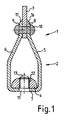
- the caterpillar web 1 comprises one elongated base body 2, a sheath 3 and a Screw strip 4.
- the basic body 2 consists essentially from two side legs 5, 6 with one in between arranged connecting web 7.
- the side legs 5, 6 are first aligned perpendicular to connecting web 7 and form a U-shaped cross-section in this area. over the side legs become a kink in the further course led inside and go over another kink in a section 8, 9 about that in the present Embodiment substantially perpendicular to Connecting web 7 is aligned and in which the Side legs so parallel to each other at a distance run that between the legs, the cutting edge 3 can be used.
- a Rivet connection to be provided for secure attachment of the cutting edge 3, as in the present exemplary embodiment.
- the Side legs 5, 7 in parallel section 8, 9 and the cutting edge 3 suitable holes.
- the screw strip 4 serves as a crawler (not shown). For this purpose there are 7 recesses or bores in the connecting web 11 attached to the threaded holes 12 of the Insert screw strip corresponding screw thread 13 to be able to.
- Fig. 2 differs from that 1 in that the cutting edge 3 is not by a Rivet connection 10, but by two welds 14, 15 am Base body 2 is attached.
- the welds are on the top End of the sections 8, 9 running parallel at a distance arranged.
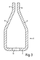
- sections 8, 9 do not run as in Fig. 1 in a slope 16, 17, so as to be uniform Create transition to cutting edge 3, but form at the Cut 3 a paragraph that is to accommodate the Welds 14, 15 suitable that fill the paragraph and on this way the desired smooth transition to Create cutting edge 3.
- FIG. 3 is the base body according to FIG. 2 for welding the cutting edge 3 shown separately.
- FIG. 4 shows an embodiment in which one Cut 18 continuously in the base body 2 to Connecting bridge 7 runs.
- the cutting edge is 18 for example at the end of the parallel sections 8, 9 of the side legs 5, 6 welded.
- To train the Holding the cutting edge 18 in the area of the connecting web 7 is this in a thicker material and has a groove 19 in which the cutting edge 18 is guided and prevents them from moving sideways or downwards.
- An arrangement of this kind primarily makes caterpillar webs Shear forces in the direction of the cutting edge 18 at the connection point of cutting edge and body in the area of parallel trending sections 8, 9 intercepted. With that the Fatigue strength of the base body / cutting connection and thus increases the reliability of the crawler track.
- Fig. 5 it is evident that it is sufficient if the cutting edge 8, 10 only is partially guided in the groove 19 and otherwise according to the Recesses 20 is reset. That way Material saved and thus the total weight of the Caterpillar web reduced.
- FIG. 6 Another embodiment is shown in FIG. 6.
- a cutting edge 21 runs continuously up to the connecting bridge 7.
- the attachment of the Cutting edge 21 is in the same way as in the exemplary embodiment 1 in the form of a riveted joint 10.
- the same base body 2 as in the first Embodiment can be used.
- the cutting edge 21 ends not in a groove, but merges into a foot part 22, the rests on the connecting web 7.
- Threaded bores 23 are provided, by means of which the Cut 21 fastened together with the complete caterpillar web can be.
- the connecting web 7 of the Basic body 2 bores or recesses 11 are provided allow it, e.g. B.
- FIG. 7a a screw thread (not shown) in to introduce the threaded bore 23.
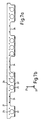
- a cutting edge 21 is in the front and side view shown in Fig. 7a and b.
- recesses 24 are present that lead to a Weight saving.
- Fig. 7a furthermore bores 26 for the riveted joint 10 see.
- the base body can as an extruded profile (preferably for aluminum) by a Rolling process or a bending process (preferably at Steel).
- the basic body 2 is made of plastic, preferably made of fiber-reinforced synthetic resin. After Production of the base body, it is not necessary that the sections 8 running parallel in the assembled state, 9 already have this shape, since the side legs 5, 6 if necessary, even in the elastic range in their position can be changed. By the invention Execution of the base body, it is therefore possible that in different thicknesses for the cutting edges 3, 18, 21 can be used without the base body to have to change.
Landscapes
- Engineering & Computer Science (AREA)
- Combustion & Propulsion (AREA)
- Transportation (AREA)
- Mechanical Engineering (AREA)
- Chemical & Material Sciences (AREA)
- Sawing (AREA)
- Handcart (AREA)
- Control Of Position, Course, Altitude, Or Attitude Of Moving Bodies (AREA)
- Non-Deflectable Wheels, Steering Of Trailers, Or Other Steering (AREA)
- A Measuring Device Byusing Mechanical Method (AREA)
- Road Repair (AREA)
- Treatment Of Fiber Materials (AREA)
- Body Structure For Vehicles (AREA)
Applications Claiming Priority (2)
| Application Number | Priority Date | Filing Date | Title |
|---|---|---|---|
| DE19755581A DE19755581A1 (de) | 1997-12-13 | 1997-12-13 | Raupensteg für Laufketten von Raupenfahrzeugen, insbesondere für Pisten- oder Loipenspurgeräte |
| DE19755581 | 1997-12-13 |
Publications (3)
| Publication Number | Publication Date |
|---|---|
| EP0922629A2 true EP0922629A2 (fr) | 1999-06-16 |
| EP0922629A3 EP0922629A3 (fr) | 2000-05-31 |
| EP0922629B1 EP0922629B1 (fr) | 2003-05-07 |
Family
ID=7851891
Family Applications (1)
| Application Number | Title | Priority Date | Filing Date |
|---|---|---|---|
| EP98123673A Expired - Lifetime EP0922629B1 (fr) | 1997-12-13 | 1998-12-11 | Crampon pour chenille de véhicule à chenille, particulièrement pour machines pour la préparation ou la réfection de pistes de ski |
Country Status (5)
| Country | Link |
|---|---|
| US (1) | US6296330B1 (fr) |
| EP (1) | EP0922629B1 (fr) |
| AT (1) | ATE239638T1 (fr) |
| CA (1) | CA2255502C (fr) |
| DE (2) | DE19755581A1 (fr) |
Cited By (1)
| Publication number | Priority date | Publication date | Assignee | Title |
|---|---|---|---|---|
| IT201600096899A1 (it) * | 2016-09-27 | 2018-03-27 | Prinoth Spa | Barra trasversale per cingoli di veicoli battipista |
Families Citing this family (29)
| Publication number | Priority date | Publication date | Assignee | Title |
|---|---|---|---|---|
| DE29913344U1 (de) * | 1999-07-30 | 2000-12-07 | Kässbohrer Geländefahrzeug AG, 89250 Senden | Kettensteg für Laufketten |
| US7500143B2 (en) * | 2000-05-05 | 2009-03-03 | Computer Associates Think, Inc. | Systems and methods for managing and analyzing faults in computer networks |
| US7752024B2 (en) * | 2000-05-05 | 2010-07-06 | Computer Associates Think, Inc. | Systems and methods for constructing multi-layer topological models of computer networks |
| US7237138B2 (en) * | 2000-05-05 | 2007-06-26 | Computer Associates Think, Inc. | Systems and methods for diagnosing faults in computer networks |
| AU2001261258A1 (en) * | 2000-05-05 | 2001-11-20 | Aprisma Management Technologies, Inc. | Help desk systems and methods for use with communications networks |
| DE10029467C1 (de) * | 2000-06-21 | 2002-04-18 | Daimler Chrysler Ag | Verfahren zum Versteifen umfänglich geschlossener Hohlprofile |
| US6609772B2 (en) * | 2001-07-09 | 2003-08-26 | International Engineering And Manufacturing, Inc. | Traction stud force distributing backer member |
| US6540310B1 (en) * | 2002-02-01 | 2003-04-01 | Ironwood Designs Llc | Grouser |
| DE10303485B4 (de) * | 2003-01-24 | 2010-05-27 | Kässbohrer Geländefahrzeug AG | Kettensteg für eine Laufkette eines Kettenfahrzeugs |
| AT501048B8 (de) * | 2004-12-22 | 2007-02-15 | Prinoth A G | Kettensteg für eine laufkette von raupenfahrzeugen, insbesondere pistenfahrzeuge oder loipenspurgeräte |
| WO2006069682A1 (fr) * | 2004-12-22 | 2006-07-06 | Prinoth Ag | Etançon pour chenille de vehicules chenilles, en particulier de vehicules pisteurs ou d'appareils traceurs de pistes de ski |
| EP1674382A1 (fr) * | 2004-12-22 | 2006-06-28 | Prinoth A.G. | Crampon pour chenilles |
| DE502006006646D1 (de) * | 2006-10-06 | 2010-05-20 | Rolic Invest Sarl | Raupenfahrzeug |
| ITMI20071249A1 (it) * | 2007-06-21 | 2008-12-22 | Rolic Invest Sarl | Rampone per cingoli di veicoli cingolati, in particolare veicoli battipista |
| ITMI20072091A1 (it) * | 2007-10-30 | 2009-04-30 | Rolic Invest Sarl | Fresa rotante da neve e metodo per la preparazione del manto nevoso delle piste da sci |
| ITMI20072096A1 (it) * | 2007-10-30 | 2009-04-30 | Rolic Invest Sarl | Dispositivo di collegamento fra un veicolo battipista ed un'attrezzatura per la preparazione del manto nevoso delle piste da sci e metodo di controllo impiegante tale dispositivo di collegamento |
| ITMI20072105A1 (it) * | 2007-10-31 | 2009-05-01 | Rolic Invest Sarl | Fresa rotante da neve per la preparazione del manto nevoso delle piste da sci |
| ITMI20072102A1 (it) * | 2007-10-31 | 2009-05-01 | Rolic Invest Sarl | Fresa rotante da neve per la preparazione del manto nevoso delle piste da sci |
| US20100312646A1 (en) * | 2007-12-21 | 2010-12-09 | Yahoo! Inc. | System for serving advertisements targeted to geographic areas over mobile devices |
| ITMI20081001A1 (it) * | 2008-05-29 | 2009-11-30 | Rolic Invest Sarl | Cingolo per veicoli battipista e veicolo battipista provvisto di tale cingolo |
| IT1394923B1 (it) | 2009-02-18 | 2012-07-27 | Rolic Invest Sarl | Veicolo battipista comprendente un gruppo verricello di ausilio alla movimentazione del veicolo battipista lungo pendii ripidi e metodo di azionamento del gruppo verricello |
| US9242685B2 (en) * | 2011-08-25 | 2016-01-26 | Liberty Products, Inc. | Snowmobile track stud support |
| US9346241B2 (en) * | 2014-01-15 | 2016-05-24 | Ford Global Technologies, Llc | Composite panel for joining with a clinch joint and method of forming a clinch joint |
| DE102014001006A1 (de) * | 2014-01-29 | 2015-07-30 | Hans Hall Gmbh | Traktionskette für eine Raupenkette eines Kettenfahrzeugs sowie Bausatz für eine Raupenkette |
| DE202014102210U1 (de) * | 2014-05-12 | 2014-07-11 | Hans Hall Gmbh | Raupensteg |
| ITUB20160844A1 (it) * | 2016-02-18 | 2017-08-18 | Prinoth Spa | Barra trasversale per un cingolo di un veicolo cingolato, in particolare di un veicolo battipista |
| DE102019132444A1 (de) * | 2019-11-29 | 2021-06-02 | Hans Hall Gmbh | Raupensteg für eine Laufkette eines Raupenfahrzeugs |
| DE102019220532A1 (de) * | 2019-12-23 | 2021-06-24 | Kässbohrer Geländefahrzeug Aktiengesellschaft | Kettensteg für ein Kettenfahrzeug und Verfahren zur Herstellung eines solchen Kettensteges |
| US11347579B1 (en) | 2021-04-29 | 2022-05-31 | Bank Of America Corporation | Instinctive slither application assessment engine |
Citations (3)
| Publication number | Priority date | Publication date | Assignee | Title |
|---|---|---|---|---|
| CH644558A5 (en) | 1979-05-18 | 1984-08-15 | Alusuisse | Caterpillar track for caterpillar vehicles |
| EP0381642A2 (fr) | 1989-01-12 | 1990-08-08 | Norbert Krainer | Chenille pour engin à damer les pistes de ski |
| EP0414208A1 (fr) | 1989-08-21 | 1991-02-27 | Karl Kässbohrer Fahrzeugwerke GmbH | Barrette en acier pour chenilles |
Family Cites Families (11)
| Publication number | Priority date | Publication date | Assignee | Title |
|---|---|---|---|---|
| US3165364A (en) * | 1961-03-01 | 1965-01-12 | Utah Scient Res Foundation | Smooth-riding self-cleaning endless track |
| BE639641A (fr) * | 1961-03-10 | |||
| US3883190A (en) * | 1973-10-03 | 1975-05-13 | Jr James Anthony Kilbane | Snowmobile traction cleat and drive belt |
| US3829174A (en) * | 1973-10-29 | 1974-08-13 | Flextac Nodwell Ltd | Gang plate fastening assembly and endless track formed therewith |
| NL7707261A (nl) * | 1977-06-30 | 1979-01-03 | Texas Industries Inc | Flexibele rupsband. |
| US5265949A (en) * | 1989-08-21 | 1993-11-30 | Kassbohrer Karl Fahrzeugwerke Gmbh | Steel crosspiece |
| US5284386A (en) * | 1991-07-15 | 1994-02-08 | Rubel Edward R | Multi facet traction device |
| DE9303466U1 (de) * | 1993-03-09 | 1994-07-14 | Hoogovens Aluminium Profiltechnik GmbH, 56070 Koblenz | Kettenelement |
| US5354124A (en) * | 1993-09-07 | 1994-10-11 | Lmc Operating Corp. | Water sealed, cable reinforced vehicle endless track and cleat assembly |
| DE29602940U1 (de) * | 1996-02-20 | 1997-06-19 | Kaessbohrer Geländefahrzeug GmbH, 89250 Senden | Kettenstegprofil |
| DE29608376U1 (de) * | 1996-05-10 | 1996-07-25 | Jäger, Arnold, 31303 Burgdorf | Laufband für Raupenfahrzeuge, insb. Schneefahrzeuge |
-
1997
- 1997-12-13 DE DE19755581A patent/DE19755581A1/de not_active Withdrawn
-
1998
- 1998-12-11 CA CA002255502A patent/CA2255502C/fr not_active Expired - Fee Related
- 1998-12-11 DE DE59808249T patent/DE59808249D1/de not_active Expired - Fee Related
- 1998-12-11 EP EP98123673A patent/EP0922629B1/fr not_active Expired - Lifetime
- 1998-12-11 AT AT98123673T patent/ATE239638T1/de active
- 1998-12-14 US US09/210,625 patent/US6296330B1/en not_active Expired - Lifetime
Patent Citations (3)
| Publication number | Priority date | Publication date | Assignee | Title |
|---|---|---|---|---|
| CH644558A5 (en) | 1979-05-18 | 1984-08-15 | Alusuisse | Caterpillar track for caterpillar vehicles |
| EP0381642A2 (fr) | 1989-01-12 | 1990-08-08 | Norbert Krainer | Chenille pour engin à damer les pistes de ski |
| EP0414208A1 (fr) | 1989-08-21 | 1991-02-27 | Karl Kässbohrer Fahrzeugwerke GmbH | Barrette en acier pour chenilles |
Cited By (3)
| Publication number | Priority date | Publication date | Assignee | Title |
|---|---|---|---|---|
| IT201600096899A1 (it) * | 2016-09-27 | 2018-03-27 | Prinoth Spa | Barra trasversale per cingoli di veicoli battipista |
| WO2018060884A1 (fr) * | 2016-09-27 | 2018-04-05 | Prinoth S.P.A. | Barre transversale pour chenilles de dameuses |
| US11299221B2 (en) | 2016-09-27 | 2022-04-12 | Prinoth S.P.A. | Transverse bar for tracks of snow groomers |
Also Published As
| Publication number | Publication date |
|---|---|
| EP0922629B1 (fr) | 2003-05-07 |
| DE19755581A1 (de) | 1999-06-17 |
| US6296330B1 (en) | 2001-10-02 |
| CA2255502C (fr) | 2009-02-17 |
| CA2255502A1 (fr) | 1999-06-13 |
| ATE239638T1 (de) | 2003-05-15 |
| EP0922629A3 (fr) | 2000-05-31 |
| DE59808249D1 (de) | 2003-06-12 |
Similar Documents
| Publication | Publication Date | Title |
|---|---|---|
| EP0922629B1 (fr) | Crampon pour chenille de véhicule à chenille, particulièrement pour machines pour la préparation ou la réfection de pistes de ski | |
| EP0756674B2 (fr) | Entretoise pour chaine conductrice d'energie | |
| EP1161972A2 (fr) | Planche de glisse, notamment ski ainsi qu'un système de rails profilés pour une telle planche de glisse | |
| EP1245254B1 (fr) | Ski, notamment ski alpin | |
| EP2778028A2 (fr) | Système de barre pour une chenille d'entraînement d'un véhicule à chenilles | |
| EP2918482B1 (fr) | Chaîne de traction pour une chenille d'un véhicule à chenille et kit pour une chenille | |
| EP3081462B1 (fr) | Systeme de barre de chenille d'entrainement de dameur de piste, procede de fabrication d'un profile de barre pour chenille pour un tel systeme de barre pour chenille et chenille d'entrainement de dameur de piste | |
| EP0391247A2 (fr) | Convoyeur à bande portant des rouleaux d'accumulation | |
| EP1827954B1 (fr) | Crampon conçu pour une chaine a chenille de vehicule chenille, notamment pour une chaine a chenille de vehicule de piste, ou de motoneige | |
| DE1605570B2 (de) | Fahrzeug-gleiskette | |
| DE2516082C2 (de) | Rinnenschuß für Kettenkratzförderer | |
| DE3414440A1 (de) | Ski aus einem mit einer laufflaeche versehenen skikoerper | |
| EP1366785A1 (fr) | Ski, procédé de montage d'une fixation de ski au dit ski et fabrication de tels skis | |
| DE202018103267U1 (de) | Raupensteg einer Raupenkette | |
| EP2150374B1 (fr) | Système à coulisseau pour machines-outils | |
| DE29602940U1 (de) | Kettenstegprofil | |
| EP3798108A1 (fr) | Système de chaîne pour une dameuse | |
| EP3828060B1 (fr) | Crampon pour un chemin de roulement d'un véhicule à chenilles | |
| EP0414208A1 (fr) | Barrette en acier pour chenilles | |
| DE3802914C2 (fr) | ||
| AT403888B (de) | Ski, insbesondere alpinski | |
| EP0334299A1 (fr) | Crampon | |
| EP1809396B1 (fr) | Dispositif pour fixer une fixation sur un ski | |
| DE1605570C3 (de) | Fahrzeug-Gleiskette | |
| DE10237765B4 (de) | Bindungsplatte für ein Schneegleitbrett, insbesondere Ski sowie Schneegleitbrett mit einer solchen Bindungsplatte |
Legal Events
| Date | Code | Title | Description |
|---|---|---|---|
| PUAI | Public reference made under article 153(3) epc to a published international application that has entered the european phase |
Free format text: ORIGINAL CODE: 0009012 |
|
| AK | Designated contracting states |
Kind code of ref document: A2 Designated state(s): AT CH DE FR IT LI |
|
| AX | Request for extension of the european patent |
Free format text: AL;LT;LV;MK;RO;SI |
|
| PUAL | Search report despatched |
Free format text: ORIGINAL CODE: 0009013 |
|
| AK | Designated contracting states |
Kind code of ref document: A3 Designated state(s): AT BE CH CY DE DK ES FI FR GB GR IE IT LI LU MC NL PT SE |
|
| AX | Request for extension of the european patent |
Free format text: AL;LT;LV;MK;RO;SI |
|
| 17P | Request for examination filed |
Effective date: 20001123 |
|
| AKX | Designation fees paid |
Free format text: AT CH DE FR IT LI |
|
| 17Q | First examination report despatched |
Effective date: 20020201 |
|
| GRAH | Despatch of communication of intention to grant a patent |
Free format text: ORIGINAL CODE: EPIDOS IGRA |
|
| GRAH | Despatch of communication of intention to grant a patent |
Free format text: ORIGINAL CODE: EPIDOS IGRA |
|
| GRAA | (expected) grant |
Free format text: ORIGINAL CODE: 0009210 |
|
| AK | Designated contracting states |
Designated state(s): AT CH DE FR IT LI |
|
| REG | Reference to a national code |
Ref country code: CH Ref legal event code: EP |
|
| REF | Corresponds to: |
Ref document number: 59808249 Country of ref document: DE Date of ref document: 20030612 Kind code of ref document: P |
|
| REG | Reference to a national code |
Ref country code: CH Ref legal event code: NV Representative=s name: KATZAROV S.A. |
|
| ET | Fr: translation filed | ||
| PLBE | No opposition filed within time limit |
Free format text: ORIGINAL CODE: 0009261 |
|
| STAA | Information on the status of an ep patent application or granted ep patent |
Free format text: STATUS: NO OPPOSITION FILED WITHIN TIME LIMIT |
|
| 26N | No opposition filed |
Effective date: 20040210 |
|
| PGFP | Annual fee paid to national office [announced via postgrant information from national office to epo] |
Ref country code: DE Payment date: 20090106 Year of fee payment: 11 |
|
| PGFP | Annual fee paid to national office [announced via postgrant information from national office to epo] |
Ref country code: IT Payment date: 20081230 Year of fee payment: 11 |
|
| PG25 | Lapsed in a contracting state [announced via postgrant information from national office to epo] |
Ref country code: DE Free format text: LAPSE BECAUSE OF NON-PAYMENT OF DUE FEES Effective date: 20100701 |
|
| PGFP | Annual fee paid to national office [announced via postgrant information from national office to epo] |
Ref country code: FR Payment date: 20110104 Year of fee payment: 13 Ref country code: AT Payment date: 20101213 Year of fee payment: 13 |
|
| PGFP | Annual fee paid to national office [announced via postgrant information from national office to epo] |
Ref country code: CH Payment date: 20101217 Year of fee payment: 13 |
|
| PG25 | Lapsed in a contracting state [announced via postgrant information from national office to epo] |
Ref country code: IT Free format text: LAPSE BECAUSE OF NON-PAYMENT OF DUE FEES Effective date: 20091211 |
|
| REG | Reference to a national code |
Ref country code: CH Ref legal event code: PL |
|
| REG | Reference to a national code |
Ref country code: FR Ref legal event code: ST Effective date: 20120831 |
|
| PG25 | Lapsed in a contracting state [announced via postgrant information from national office to epo] |
Ref country code: LI Free format text: LAPSE BECAUSE OF NON-PAYMENT OF DUE FEES Effective date: 20111231 Ref country code: CH Free format text: LAPSE BECAUSE OF NON-PAYMENT OF DUE FEES Effective date: 20111231 |
|
| REG | Reference to a national code |
Ref country code: AT Ref legal event code: MM01 Ref document number: 239638 Country of ref document: AT Kind code of ref document: T Effective date: 20111211 |
|
| PG25 | Lapsed in a contracting state [announced via postgrant information from national office to epo] |
Ref country code: AT Free format text: LAPSE BECAUSE OF NON-PAYMENT OF DUE FEES Effective date: 20111211 |
|
| PG25 | Lapsed in a contracting state [announced via postgrant information from national office to epo] |
Ref country code: FR Free format text: LAPSE BECAUSE OF NON-PAYMENT OF DUE FEES Effective date: 20120102 |