EP0922871A1 - Dynamisches Fluidlager - Google Patents
Dynamisches Fluidlager Download PDFInfo
- Publication number
- EP0922871A1 EP0922871A1 EP98308805A EP98308805A EP0922871A1 EP 0922871 A1 EP0922871 A1 EP 0922871A1 EP 98308805 A EP98308805 A EP 98308805A EP 98308805 A EP98308805 A EP 98308805A EP 0922871 A1 EP0922871 A1 EP 0922871A1
- Authority
- EP
- European Patent Office
- Prior art keywords
- bearing
- sleeve
- plate
- shaft
- dynamic fluid
- Prior art date
- Legal status (The legal status is an assumption and is not a legal conclusion. Google has not performed a legal analysis and makes no representation as to the accuracy of the status listed.)
- Granted
Links
- 239000012530 fluid Substances 0.000 title claims abstract description 34
- 239000000853 adhesive Substances 0.000 claims abstract description 22
- 230000001070 adhesive effect Effects 0.000 claims abstract description 22
- 230000004888 barrier function Effects 0.000 claims abstract description 13
- 230000035939 shock Effects 0.000 claims abstract description 13
- 238000009792 diffusion process Methods 0.000 claims abstract description 10
- 239000004593 Epoxy Substances 0.000 claims abstract description 4
- 238000007789 sealing Methods 0.000 claims abstract description 4
- 238000003860 storage Methods 0.000 claims description 12
- 239000000314 lubricant Substances 0.000 claims description 6
- 238000001704 evaporation Methods 0.000 abstract description 7
- 230000008020 evaporation Effects 0.000 abstract description 7
- 230000003247 decreasing effect Effects 0.000 description 3
- 238000004519 manufacturing process Methods 0.000 description 3
- 238000000034 method Methods 0.000 description 2
- 238000000926 separation method Methods 0.000 description 2
- 239000000725 suspension Substances 0.000 description 2
- 230000001154 acute effect Effects 0.000 description 1
- 239000003570 air Substances 0.000 description 1
- 239000012080 ambient air Substances 0.000 description 1
- 230000006835 compression Effects 0.000 description 1
- 238000007906 compression Methods 0.000 description 1
- 238000010276 construction Methods 0.000 description 1
- 238000006073 displacement reaction Methods 0.000 description 1
- 238000009826 distribution Methods 0.000 description 1
- 210000003027 ear inner Anatomy 0.000 description 1
- 210000003128 head Anatomy 0.000 description 1
- 238000009434 installation Methods 0.000 description 1
- 238000003475 lamination Methods 0.000 description 1
- 230000003068 static effect Effects 0.000 description 1
Images


Classifications
-
- F—MECHANICAL ENGINEERING; LIGHTING; HEATING; WEAPONS; BLASTING
- F16—ENGINEERING ELEMENTS AND UNITS; GENERAL MEASURES FOR PRODUCING AND MAINTAINING EFFECTIVE FUNCTIONING OF MACHINES OR INSTALLATIONS; THERMAL INSULATION IN GENERAL
- F16C—SHAFTS; FLEXIBLE SHAFTS; ELEMENTS OR CRANKSHAFT MECHANISMS; ROTARY BODIES OTHER THAN GEARING ELEMENTS; BEARINGS
- F16C33/00—Parts of bearings; Special methods for making bearings or parts thereof
- F16C33/02—Parts of sliding-contact bearings
- F16C33/04—Brasses; Bushes; Linings
- F16C33/06—Sliding surface mainly made of metal
- F16C33/10—Construction relative to lubrication
- F16C33/1025—Construction relative to lubrication with liquid, e.g. oil, as lubricant
- F16C33/106—Details of distribution or circulation inside the bearings, e.g. details of the bearing surfaces to affect flow or pressure of the liquid
- F16C33/107—Grooves for generating pressure
-
- F—MECHANICAL ENGINEERING; LIGHTING; HEATING; WEAPONS; BLASTING
- F16—ENGINEERING ELEMENTS AND UNITS; GENERAL MEASURES FOR PRODUCING AND MAINTAINING EFFECTIVE FUNCTIONING OF MACHINES OR INSTALLATIONS; THERMAL INSULATION IN GENERAL
- F16C—SHAFTS; FLEXIBLE SHAFTS; ELEMENTS OR CRANKSHAFT MECHANISMS; ROTARY BODIES OTHER THAN GEARING ELEMENTS; BEARINGS
- F16C33/00—Parts of bearings; Special methods for making bearings or parts thereof
- F16C33/72—Sealings
- F16C33/74—Sealings of sliding-contact bearings
-
- G—PHYSICS
- G11—INFORMATION STORAGE
- G11B—INFORMATION STORAGE BASED ON RELATIVE MOVEMENT BETWEEN RECORD CARRIER AND TRANSDUCER
- G11B19/00—Driving, starting, stopping record carriers not specifically of filamentary or web form, or of supports therefor; Control thereof; Control of operating function ; Driving both disc and head
- G11B19/20—Driving; Starting; Stopping; Control thereof
- G11B19/2009—Turntables, hubs and motors for disk drives; Mounting of motors in the drive
- G11B19/2018—Incorporating means for passive damping of vibration, either in the turntable, motor or mounting
-
- H—ELECTRICITY
- H02—GENERATION; CONVERSION OR DISTRIBUTION OF ELECTRIC POWER
- H02K—DYNAMO-ELECTRIC MACHINES
- H02K5/00—Casings; Enclosures; Supports
- H02K5/04—Casings or enclosures characterised by the shape, form or construction thereof
- H02K5/16—Means for supporting bearings, e.g. insulating supports or means for fitting bearings in the bearing-shields
- H02K5/167—Means for supporting bearings, e.g. insulating supports or means for fitting bearings in the bearing-shields using sliding-contact or spherical cap bearings
- H02K5/1677—Means for supporting bearings, e.g. insulating supports or means for fitting bearings in the bearing-shields using sliding-contact or spherical cap bearings radially supporting the rotor around a fixed spindle; radially supporting the rotor directly
-
- F—MECHANICAL ENGINEERING; LIGHTING; HEATING; WEAPONS; BLASTING
- F16—ENGINEERING ELEMENTS AND UNITS; GENERAL MEASURES FOR PRODUCING AND MAINTAINING EFFECTIVE FUNCTIONING OF MACHINES OR INSTALLATIONS; THERMAL INSULATION IN GENERAL
- F16C—SHAFTS; FLEXIBLE SHAFTS; ELEMENTS OR CRANKSHAFT MECHANISMS; ROTARY BODIES OTHER THAN GEARING ELEMENTS; BEARINGS
- F16C2370/00—Apparatus relating to physics, e.g. instruments
- F16C2370/12—Hard disk drives or the like
-
- G—PHYSICS
- G11—INFORMATION STORAGE
- G11B—INFORMATION STORAGE BASED ON RELATIVE MOVEMENT BETWEEN RECORD CARRIER AND TRANSDUCER
- G11B25/00—Apparatus characterised by the shape of record carrier employed but not specific to the method of recording or reproducing, e.g. dictating apparatus; Combinations of such apparatus
- G11B25/04—Apparatus characterised by the shape of record carrier employed but not specific to the method of recording or reproducing, e.g. dictating apparatus; Combinations of such apparatus using flat record carriers, e.g. disc, card
- G11B25/043—Apparatus characterised by the shape of record carrier employed but not specific to the method of recording or reproducing, e.g. dictating apparatus; Combinations of such apparatus using flat record carriers, e.g. disc, card using rotating discs
-
- H—ELECTRICITY
- H02—GENERATION; CONVERSION OR DISTRIBUTION OF ELECTRIC POWER
- H02K—DYNAMO-ELECTRIC MACHINES
- H02K5/00—Casings; Enclosures; Supports
- H02K5/04—Casings or enclosures characterised by the shape, form or construction thereof
- H02K5/12—Casings or enclosures characterised by the shape, form or construction thereof specially adapted for operating in liquid or gas
- H02K5/124—Sealing of shafts
Definitions
- This invention relates in general to a dynamic fluid bearing for use in a spindle motor, for example in a disk drive.
- Disk drives are computer mass storage devices from which data may be read and/or to which such data may be written. In general, they comprise one or more randomly accessible rotating storage media, or disks, on which data is encoded by various means. In magnetic disk drives, data is encoded as bits of information including magnetic field reversals grouped in tracks on the magnetically-hard surface of the rotating disks. The disks are stacked in a generally parallel and spaced-apart relationship and affixed at their inner diameter ( ID ) to a common hub which is rotationally coupled to a stationary spindle shaft by a pair of bearings, typically ball bearings.
- Rotary spindle motors having fluid bearings for supporting the rotary member rather than traditional ball bearings typically include a shaft having at least one axial thrust plate and a hub, which may be a rotary hub, having a sleeve portion generally enclosing the shaft and thrust plate, thus forming a journal bearing with bearing fluid disposed therein.
- the bearing fluid will form capillary seals at one or more ends of the shaft that are exposed to ambient air pressure.
- the problem with such constructions is that under certain conditions the capillary seal may break down and fluid may leak from the bearing. Disruption of the seal may be caused by shock or vibration. Under certain conditions the rotating portion of the bearing may be displaced along the axis of the shaft. In the normal course of events, lubricant flows around the end of the thrust plate from the side with decreasing clearance to the side with increasing clearance. If, however, because of sudden shock or vibration, the lubricant flow around the thrust plate is impeded, fluid will be pushed toward one end of the shaft or the other, possibly breaking down the surface tension which holds the seal in place.
- Leakage may also occur when there are inaccuracies in the fabrication of the patterned grooves used by the thrust plates upper and lower surfaces to maintain a desired net pressure gradient.
- the object of the grooves is to create a high pressure region in the middle of each thrust plate surface and to create ambient pressure zones at the inner diameter of the thrust plate, adjacent the shaft, and at the outer diameter in the gap between the readily outermost edge of the thrust plate and the sleeve.
- This type of pressure distribution ordinarily results in no displacement of bearing fluid, that is, the static pressures will equalize.
- fabrication inaccuracies do occur, as does tilt in the bearing, or any other physical phenomena, and these factors can alter the pressure balance in the bearing fluid resulting in flow across the bearing.
- the flow of bearing fluid can overcome the surface tension seal at either end of the bearing and cause the fluid to leak.
- the situation is particularly acute at the thrust plate end where pressure imbalances between the upper and lower surfaces of the thrust plate may create a net flow which is near the capillary seal at the upper surface of the thrust plate.
- prior axial bearing support structures have not simultaneously address preventing oil from leaking out, maintaining the bearing integrity under shock, reducing oil evaporation and minimizing distortion of the active bearing surface. Rather, existing designs have addressed only a fraction of the requirements, e.g., only evaporation and shock induced bearing separation or distortion and evaporation.
- the dynamic groove bearing includes a sleeve-like housing having a locking piece that includes a bearing disk portion which cooperates with an annular bearing disk provided on a shaft.
- a pressure member is adapted to compress an annular, elastically deformable sealing element to thereby seal the interface between the housing and the locking piece and to pretension the locking piece against a seat formed on the housing.
- Muller et al. does not address evaporation and shock induced bearing separation.
- the present invention provides a dynamic fluid bearing for a spindle motor having a thrust plate secured to a shaft and a bearing plate and load plate secured to a sleeve, wherein the load plate urges the bearing plate towards the thrust plate, and characterised in that an adhesive is interposed between the load plate and the thrust plate.
- Such a bearing with a fluid bearing seal and support structure simultaneously addresses preventing oil from leaking out, maintaining the bearing integrity under shock, reducing oil evaporation and minimizing distortion of the active bearing surface.
- the adhesive is an UV epoxy, and there is a first diffusion barrier disposed between the load plate and the shaft, and a further diffusion barrier disposed between the sleeve and the shaft.
- An O-ring is disposed above (ie adjacent) the bearing plate for sealing a gap between the bearing plate and the sleeve. The adhesive maintains integrity between the load plate and the bearing plate when a shock condition occurs.
- the invention provides a spindle motor, comprising:
- the invention supplies a method for providing a dynamic fluid bearing for a spindle motor having a thrust plate secured to a shaft and a bearing plate and a load plate secured to a sleeve, wherein the load plate urges the bearing plate towards the thrust plate, the method comprising the steps of applying an adhesive between the load plate and the thrust plate and curing the adhesive to form the seal.
- a disk drive comprising:
- the preferred embodiment provides a fluid bearing seal and support structure that may simultaneously prevent oil leakage, maintain the bearing integrity under shock, reduce oil evaporation and minimize distortion of the active bearing surface.
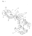
- Fig. 1 illustrates an exploded view of a magnetic storage system 100.
- the disk drive 100 includes a housing 112 and a housing cover 114 which, after assembly, is mounted within a frame 116.
- Mounted within the housing is a spindle shaft 122.
- Rotatably attached to the spindle shaft 122 are a number of magnetic storage disks 124.
- multiple disks 124 are attached to the spindle shaft 122 in spaced apart relation.
- the disks 124 rotate on spindle shaft 122 which is powered by a motor (not shown) .
- Information is written on or read from the disks 124 by heads or magnetic transducers (not shown) which are supported by sliders 126.
- sliders 126 are coupled to the suspensions or load springs 128.
- the load springs 128 are attached to separate arms 130 on an E block or comb 132.
- the E block or comb 132 is attached at one end of an actuator arm assembly 136.
- the actuator arm assembly 136 is rotatably attached within the housing 112 on an actuator shaft 138.
- the rotary actuator assembly 136 moves the integrated transducer/suspension assembly in an arcuate path across the surface of the storage disk 124.
- Fig. 2 illustrates the configuration of a fluid bearing seal 200 for a spindle motor according to the present invention.
- Hydrodynamic pressure is generated at the axial bearing 210 and the axial bearing plate 214 when the bearing surfaces 216, 218 are rotating with respect to each other. Therefore, bearing plate 214 must be very flat. Distortion should be minimized during and after assembly. This is accomplished by placing the O-ring 222 on top of the axial bearing plate 214.
- the O-ring 222 is placed at the interface between the axial bearing plate 214 and sleeve 230 to prevent oil from leaking out. Compression of the O-ring 222 is provided by load plate 240 through the fingers 242 or other means.
- a nominal gap such as a tenth of a millimeter.
- a gap at the axial bearing 210 can suddenly form during a vertical shock.
- the gap at the axial bearing 210 creates a vacuum that pulls air in because the O-ring 222 is highly compliant.
- This mechanism is prevented by applying a few adhesive droplets 250 between the load plate 240 and the axial bearing plate 214.
- the adhesive 250 is applied through a hole, e.g., at least two holes 180 degrees apart to maintain balance, in the load plate 240. This allows the load plate 240 to be installed immediately after oil fill and installation of bearing plate 214 and O-ring 222.
- the adhesive 250 can then be applied through the a hole 252 in the load plate 240.
- the hole 252 allows the use of a UV cure aerobic adhesive 250. This also allows adhesive 250 application at the same station as adhesive seal application at location 242.
- the adhesive 250 may be an UV epoxy, wherein a UV cure of the adhesive 250 can also be performed at the same station.
- Diffusion barriers 260, 270 are disposed near the top of the shaft just outside of the top axial bearing 210 and at the bottom of the shaft just outside of the bottom radial bearing 272.
- the diffusion barriers 260, 270 typically include narrow gaps that offer significant resistance to flow and mass transfer of lubricant vapor.
- Figs. 3 and 4 show details at the top 300 and bottom 400 areas of the spindle respectively.
- the top cross section 300 of the spindle is shown.
- the load plate 340 which secures the opposing plate of the axial plate 314 forms a first level of barrier because of the small radial gap 360 on the inner diameter near the shaft 380.
- the second barrier is formed by the narrow radial gap 382 and the relatively narrow axial gap 390.
- Radial gap 382 is located between the load plate 340 and the sleeve 330.
- the axial gap 390 is located between the axial plate 314 and the load plate 340.
- Fig. 4 shows the bottom cross section 400 of the spindle.
- a small axial gap 492 is provided between end of the sleeve 430 and the top end of the mount flange 496.
- the mount flange 496 is a press fit on the shaft 480.
- the stator mount 494 is a press fit on the mount flange 496 and is used for mounting the stator lamination stack 498.
- a long narrow annular cylindrical gap 470 is formed between the end of the sleeve 430 and the stator mount 494. Both of the above mentioned axial 492 and radial 470 gaps form effective labyrinths offering significant resistance to mass transfer of lubricant vapor.
- gaps are between rotating and stationary surfaces and have been shown to be effective in this function in the range of 0.025 to 0.050 mm. Gaps smaller than 0.025 mm could be incorporated provided manufacturing and assembly level tolerances permit them without causing surface interference. Gaps larger than 0.05 mm may be used only if calculated mass transfer rates are acceptable. For example for a radial gap of 0.025 mm at a diameter of 5 mm and a length of 2 mm for the barrier, calculated evaporative loss at 70°C amounts to about 3.25 mg over 5 years. To meet mean time between failure requirements, sufficient reservoir capacity will have to be provided so that the loss of the lubricant does not affect the functional performance of the spindle bearing system.
Landscapes
- Engineering & Computer Science (AREA)
- General Engineering & Computer Science (AREA)
- Mechanical Engineering (AREA)
- Chemical & Material Sciences (AREA)
- Oil, Petroleum & Natural Gas (AREA)
- Power Engineering (AREA)
- Sliding-Contact Bearings (AREA)
- Connection Of Motors, Electrical Generators, Mechanical Devices, And The Like (AREA)
- Sealing Of Bearings (AREA)
- Rotational Drive Of Disk (AREA)
- Motor Or Generator Frames (AREA)
Applications Claiming Priority (2)
| Application Number | Priority Date | Filing Date | Title |
|---|---|---|---|
| US08/987,823 US5957589A (en) | 1997-12-10 | 1997-12-10 | Fluid bearing seal and support structure |
| US987823 | 1997-12-10 |
Publications (2)
| Publication Number | Publication Date |
|---|---|
| EP0922871A1 true EP0922871A1 (de) | 1999-06-16 |
| EP0922871B1 EP0922871B1 (de) | 2005-01-19 |
Family
ID=25533600
Family Applications (1)
| Application Number | Title | Priority Date | Filing Date |
|---|---|---|---|
| EP98308805A Expired - Lifetime EP0922871B1 (de) | 1997-12-10 | 1998-10-27 | Dynamisches Fluidlager |
Country Status (8)
| Country | Link |
|---|---|
| US (2) | US5957589A (de) |
| EP (1) | EP0922871B1 (de) |
| JP (1) | JPH11287240A (de) |
| KR (1) | KR100318126B1 (de) |
| CN (1) | CN1095948C (de) |
| DE (1) | DE69828678T2 (de) |
| MY (1) | MY122096A (de) |
| SG (1) | SG70136A1 (de) |
Cited By (2)
| Publication number | Priority date | Publication date | Assignee | Title |
|---|---|---|---|---|
| WO2006013417A1 (en) * | 2004-07-28 | 2006-02-09 | Minebea Co., Ltd. | Fluid dynamic pressure bearing, spindle motor provided with the fluid dynamic pressure bearing, and recording disk drive device provided with the fluid dynamic pressure bearing |
| US8194347B2 (en) | 2007-08-30 | 2012-06-05 | Hitachi Global Storage Technologies, Netherlands B.V. | Designed roughness and surface treatments for capillary buffer of fluid dynamic bearings |
Families Citing this family (38)
| Publication number | Priority date | Publication date | Assignee | Title |
|---|---|---|---|---|
| US6663287B2 (en) * | 1999-12-27 | 2003-12-16 | Sankyo Seiki Mfg. Co., Ltd. | Thrust dynamic pressure bearing apparatus and method for manufacturing the same |
| US6388351B1 (en) | 1999-12-30 | 2002-05-14 | General Electric Company | Bearing load washer |
| US6809898B1 (en) * | 2000-01-13 | 2004-10-26 | Maxtor Corporation | Disk drive rocking mode vibration damper |
| JP3931207B2 (ja) * | 2000-05-10 | 2007-06-13 | 日本電産株式会社 | 流体軸受装置 |
| US6876114B2 (en) * | 2000-12-13 | 2005-04-05 | Seagate Technology Llc | Apparatus for reducing spindle motor magnetic drag |
| JP2002349553A (ja) * | 2001-05-31 | 2002-12-04 | Matsushita Electric Ind Co Ltd | 流体軸受装置 |
| CN100427779C (zh) * | 2001-11-13 | 2008-10-22 | Ntn株式会社 | 流体轴承装置 |
| JP2003169439A (ja) * | 2001-12-03 | 2003-06-13 | Hitachi Ltd | スピンドルモータとその製造方法 |
| US6746151B2 (en) | 2002-01-14 | 2004-06-08 | Seagate Technology Llc | Parallel capillary seal for a disk drive |
| US7262935B2 (en) * | 2002-11-07 | 2007-08-28 | Seagate Technology Llc | Top cover attached single plate fluid dynamic bearing motor |
| US7131770B2 (en) * | 2003-07-18 | 2006-11-07 | Minebea Co., Ltd. | Hydro fill controlling shield and sleeve for a hydrodynamic bearing |
| US7654744B2 (en) * | 2004-02-09 | 2010-02-02 | Minebea Co., Ltd. | Fluid dynamic bearing mechanism for a motor |
| US8181348B2 (en) * | 2004-04-01 | 2012-05-22 | Seagate Technology Llc | Shielding fluid reservoirs of fluid dynamic bearing motors |
| US7736061B2 (en) | 2004-06-11 | 2010-06-15 | Seiko Instruments Inc. | Fluid dynamic bearing motor, and recording-medium driving apparatus |
| US20080211334A1 (en) * | 2004-07-09 | 2008-09-04 | Yasunori Tokuno | Spindle motor |
| JP2006022931A (ja) * | 2004-07-09 | 2006-01-26 | Matsushita Electric Ind Co Ltd | スピンドルモータ |
| TWI259321B (en) * | 2004-12-21 | 2006-08-01 | Prodisc Technology Inc | Color wheel and motor thereof |
| KR100630362B1 (ko) * | 2005-01-11 | 2006-10-04 | 한국서부발전 주식회사 | 발전기 케이싱의 가스누설 방지구조 |
| JP3110389U (ja) * | 2005-02-03 | 2005-06-23 | ミネベア株式会社 | モータの流体動圧軸受装置及び該流体動圧軸受装置を備えたスピンドルモータ、記録ディスク駆動装置 |
| US7088023B1 (en) * | 2005-04-22 | 2006-08-08 | Nidec Corporation | Motor unit, manufacturing method therefor and recording disk driving apparatus |
| CN100412398C (zh) * | 2005-09-30 | 2008-08-20 | 富准精密工业(深圳)有限公司 | 流体轴承模组 |
| KR100867032B1 (ko) * | 2007-01-23 | 2008-11-04 | 삼성전기주식회사 | 스핀들모터 |
| US20080310049A1 (en) * | 2007-06-12 | 2008-12-18 | Jr-Yi Shen | Fluid dyamic bearing with novel air-gap |
| US8353630B2 (en) * | 2007-10-09 | 2013-01-15 | Hgst, Netherlands B.V. | Fluid dynamic bearing with a labyrinth seal |
| US8174788B2 (en) * | 2008-01-28 | 2012-05-08 | Hitachi Global Storage Technologies, Netherlands B.V. | Motor mount for interference suppression in a hard disk drive |
| US8619388B2 (en) * | 2008-04-22 | 2013-12-31 | HGST Netherlands B.V. | Fluid dynamic bearing with an immiscible fluid barrier |
| KR101009153B1 (ko) * | 2008-12-19 | 2011-01-18 | 삼성전기주식회사 | 스핀들모터 |
| KR101022891B1 (ko) * | 2009-02-13 | 2011-03-16 | 삼성전기주식회사 | 스핀들모터 |
| KR101070723B1 (ko) | 2009-11-27 | 2011-10-07 | 유신전기공업주식회사 | 모터 |
| EP2582022A1 (de) * | 2010-06-14 | 2013-04-17 | Panasonic Corporation | Motor und fahrzeugmontierte klimaanlage damit |
| KR101350601B1 (ko) * | 2011-11-28 | 2014-01-16 | 삼성전기주식회사 | 스핀들 모터 |
| KR20130088355A (ko) * | 2012-01-31 | 2013-08-08 | 삼성전기주식회사 | 스핀들 모터 |
| JP2014173655A (ja) * | 2013-03-08 | 2014-09-22 | Samsung Electromechanics Japan Advanced Technology Co Ltd | ディスク駆動装置 |
| DE102016206356A1 (de) * | 2016-04-15 | 2017-10-19 | Robert Bosch Gmbh | Gehäusebauteil mit einer Hydraulikleitung und deren Herstellung |
| DE102017216066B4 (de) * | 2017-09-12 | 2020-12-17 | Audi Ag | Elektromotor mit mindestens einem Kühlmittelkanal |
| CN109474109B (zh) * | 2019-01-11 | 2024-03-29 | 苏州优德通力科技有限公司 | 一种密封型外转子电机结构 |
| JP7600564B2 (ja) * | 2020-08-24 | 2024-12-17 | ニデック株式会社 | モータ、および駆動装置 |
| DE102024103959A1 (de) * | 2024-02-13 | 2025-08-14 | Minebea Mitsumi Inc. | Spindelmotor |
Citations (5)
| Publication number | Priority date | Publication date | Assignee | Title |
|---|---|---|---|---|
| JPH084769A (ja) * | 1994-06-14 | 1996-01-09 | Sankyo Seiki Mfg Co Ltd | 流体軸受装置 |
| US5559382A (en) * | 1992-10-01 | 1996-09-24 | Nidec Corporation | Spindle motor |
| EP0754871A1 (de) * | 1995-07-18 | 1997-01-22 | Quantum Corporation | Wellendichtung für hydrodynamische Lagereinheit |
| JPH0960645A (ja) * | 1995-08-26 | 1997-03-04 | Sankyo Seiki Mfg Co Ltd | 流体軸受装置の製造方法 |
| JPH09217736A (ja) * | 1996-02-09 | 1997-08-19 | Sankyo Seiki Mfg Co Ltd | 動圧軸受装置 |
Family Cites Families (19)
| Publication number | Priority date | Publication date | Assignee | Title |
|---|---|---|---|---|
| US4332428A (en) * | 1979-01-16 | 1982-06-01 | Matsushita Electric Industrial Co., Ltd. | Rotary mechanism with axial bearings |
| US4694213A (en) * | 1986-11-21 | 1987-09-15 | Ferrofluidics Corporation | Ferrofluid seal for a stationary shaft and a rotating hub |
| JPH0776569B2 (ja) * | 1986-12-26 | 1995-08-16 | 松下電器産業株式会社 | 動圧型流体軸受装置 |
| JPH073246B2 (ja) * | 1986-12-26 | 1995-01-18 | 松下電器産業株式会社 | 動圧型流体軸受装置 |
| JPS63167113A (ja) * | 1986-12-26 | 1988-07-11 | Matsushita Electric Ind Co Ltd | 動圧型流体軸受装置 |
| JP2506836B2 (ja) * | 1987-11-02 | 1996-06-12 | 松下電器産業株式会社 | 動圧型流体軸受装置 |
| US4998033A (en) * | 1989-04-12 | 1991-03-05 | Ebara Corporation | Gas dynamic bearing for spindle motor |
| JPH0335469A (ja) * | 1989-06-30 | 1991-02-15 | Matsushita Electric Ind Co Ltd | ディスク駆動装置 |
| EP0410293B1 (de) * | 1989-07-24 | 1993-09-29 | Ebara Corporation | Spindelmotor |
| EP0412509A3 (en) * | 1989-08-11 | 1992-02-26 | Ebara Corporation | Bearing structure |
| BE1007463A3 (nl) * | 1993-09-02 | 1995-07-04 | Philips Electronics Nv | Ondersteuningsinrichting met een uniform afdichtende sluitstukbevestiging, alsmede data-opslageenheid voorzien van een dergelijke ondersteuningsinrichting. |
| US5427456A (en) * | 1994-04-12 | 1995-06-27 | Synektron Corporation | Fluid bearing with asymmetrical groove pattern |
| US5433529A (en) * | 1994-08-02 | 1995-07-18 | Synektron Corporation | Fluid bearing construction employing thrust plate with pressure compensation ports |
| US5533811A (en) * | 1995-02-14 | 1996-07-09 | Quantum Corporation | Hydrodynamic bearing having inverted surface tension seals |
| US5536088A (en) * | 1995-06-07 | 1996-07-16 | Synektron Corporation | Fluid bearings for electronic spindle motors |
| US5634724A (en) * | 1995-08-25 | 1997-06-03 | Quantum Corporation | Hydrodynamic bearing for spindle motor having high inertial load |
| US5743656A (en) * | 1995-08-26 | 1998-04-28 | Sankyo Seiki Mfg. Co. Ltd. | Hydrodynamic bearing apparatus and method for manufacturing same |
| US5516212A (en) * | 1995-09-18 | 1996-05-14 | Western Digital Corporation | Hydrodynamic bearing with controlled lubricant pressure distribution |
| US5806987A (en) * | 1996-02-07 | 1998-09-15 | Sankyo Seiki Mfg. Co., Ltd. | Hydrodynamic bearing apparatus |
-
1997
- 1997-12-10 US US08/987,823 patent/US5957589A/en not_active Expired - Lifetime
-
1998
- 1998-10-27 DE DE69828678T patent/DE69828678T2/de not_active Expired - Fee Related
- 1998-10-27 EP EP98308805A patent/EP0922871B1/de not_active Expired - Lifetime
- 1998-10-28 MY MYPI98004918A patent/MY122096A/en unknown
- 1998-11-03 KR KR1019980046998A patent/KR100318126B1/ko not_active Expired - Fee Related
- 1998-11-23 SG SG1998004927A patent/SG70136A1/en unknown
- 1998-11-25 CN CN98122694A patent/CN1095948C/zh not_active Expired - Fee Related
- 1998-12-09 JP JP10350199A patent/JPH11287240A/ja active Pending
-
1999
- 1999-05-18 US US09/314,486 patent/US6339515B2/en not_active Expired - Fee Related
Patent Citations (5)
| Publication number | Priority date | Publication date | Assignee | Title |
|---|---|---|---|---|
| US5559382A (en) * | 1992-10-01 | 1996-09-24 | Nidec Corporation | Spindle motor |
| JPH084769A (ja) * | 1994-06-14 | 1996-01-09 | Sankyo Seiki Mfg Co Ltd | 流体軸受装置 |
| EP0754871A1 (de) * | 1995-07-18 | 1997-01-22 | Quantum Corporation | Wellendichtung für hydrodynamische Lagereinheit |
| JPH0960645A (ja) * | 1995-08-26 | 1997-03-04 | Sankyo Seiki Mfg Co Ltd | 流体軸受装置の製造方法 |
| JPH09217736A (ja) * | 1996-02-09 | 1997-08-19 | Sankyo Seiki Mfg Co Ltd | 動圧軸受装置 |
Non-Patent Citations (3)
| Title |
|---|
| PATENT ABSTRACTS OF JAPAN vol. 096, no. 005 31 May 1996 (1996-05-31) * |
| PATENT ABSTRACTS OF JAPAN vol. 097, no. 007 31 July 1997 (1997-07-31) * |
| PATENT ABSTRACTS OF JAPAN vol. 097, no. 012 25 December 1997 (1997-12-25) * |
Cited By (2)
| Publication number | Priority date | Publication date | Assignee | Title |
|---|---|---|---|---|
| WO2006013417A1 (en) * | 2004-07-28 | 2006-02-09 | Minebea Co., Ltd. | Fluid dynamic pressure bearing, spindle motor provided with the fluid dynamic pressure bearing, and recording disk drive device provided with the fluid dynamic pressure bearing |
| US8194347B2 (en) | 2007-08-30 | 2012-06-05 | Hitachi Global Storage Technologies, Netherlands B.V. | Designed roughness and surface treatments for capillary buffer of fluid dynamic bearings |
Also Published As
| Publication number | Publication date |
|---|---|
| EP0922871B1 (de) | 2005-01-19 |
| US6339515B2 (en) | 2002-01-15 |
| DE69828678T2 (de) | 2006-05-04 |
| US5957589A (en) | 1999-09-28 |
| DE69828678D1 (de) | 2005-02-24 |
| CN1219655A (zh) | 1999-06-16 |
| SG70136A1 (en) | 2000-01-25 |
| KR100318126B1 (ko) | 2002-02-19 |
| JPH11287240A (ja) | 1999-10-19 |
| CN1095948C (zh) | 2002-12-11 |
| MY122096A (en) | 2006-03-31 |
| US20010053042A1 (en) | 2001-12-20 |
| KR19990062551A (ko) | 1999-07-26 |
Similar Documents
| Publication | Publication Date | Title |
|---|---|---|
| EP0922871B1 (de) | Dynamisches Fluidlager | |
| US6991376B2 (en) | Low profile fluid dynamic bearing motor having increased journal span | |
| US7134792B2 (en) | Single thrust-journal bearing cup fluid dynamic bearing motor | |
| WO1996025606A1 (en) | Hydrodynamic bearing having inverted surface tension seals | |
| US5653540A (en) | Hydrodynamic bearing assembly with single sided grooved counterplace | |
| US20100053807A1 (en) | Lubricated limiter for fluid dynamic bearing motor | |
| US6756715B2 (en) | Spindle motor | |
| US7073944B2 (en) | Fluid dynamic bearing configured with an orbital ring for higher efficiency | |
| US5710678A (en) | Disc drive with self-pressurizing fluid bearing and shaft-supporting-ball retaining element | |
| US8934195B2 (en) | Fluid dynamic bearing with non-linear damping | |
| US6949852B2 (en) | Low profile thrust journal plate fluid dynamic bearing motor | |
| JP3351111B2 (ja) | ブラシレスモータ | |
| US6679632B2 (en) | Lubricant retention design for disk drive fluid dynamic bearing spindle motor | |
| US5841607A (en) | Hydrodynamic seal for disc drive spindle motor | |
| US6121703A (en) | Fluid dynamic bearing motor design for mounting a rotating shaft directly into a base casting | |
| US5997179A (en) | Multifluid application in hydrodynamic fluid bearing to reduce evaporation and control stiffness and other bearing performance | |
| US6672766B2 (en) | Easy-fill, easy-press conical bearing | |
| US6149159A (en) | High pressure boundary seal | |
| US5920443A (en) | Disk drive assembly and method having direct aerodynamic disk support | |
| US20030142889A1 (en) | Hybrid spindle bearing | |
| WO2003095852A2 (en) | Fluid dynamic bearing with non-linear damping | |
| US20010045702A1 (en) | Ferrofluid cap seal for spindle motor | |
| KR20050022005A (ko) | 유체 베어링 모터용 회전자 제한기 |
Legal Events
| Date | Code | Title | Description |
|---|---|---|---|
| PUAI | Public reference made under article 153(3) epc to a published international application that has entered the european phase |
Free format text: ORIGINAL CODE: 0009012 |
|
| AK | Designated contracting states |
Kind code of ref document: A1 Designated state(s): DE GB NL |
|
| AX | Request for extension of the european patent |
Free format text: AL;LT;LV;MK;RO;SI |
|
| 17P | Request for examination filed |
Effective date: 19990706 |
|
| AKX | Designation fees paid |
Free format text: DE GB NL |
|
| 17Q | First examination report despatched |
Effective date: 20040209 |
|
| RAP1 | Party data changed (applicant data changed or rights of an application transferred) |
Owner name: HITACHI GLOBAL STORAGE TECHNOLOGIES NETHERLANDS B. |
|
| GRAP | Despatch of communication of intention to grant a patent |
Free format text: ORIGINAL CODE: EPIDOSNIGR1 |
|
| GRAS | Grant fee paid |
Free format text: ORIGINAL CODE: EPIDOSNIGR3 |
|
| GRAA | (expected) grant |
Free format text: ORIGINAL CODE: 0009210 |
|
| AK | Designated contracting states |
Kind code of ref document: B1 Designated state(s): DE GB NL |
|
| REG | Reference to a national code |
Ref country code: GB Ref legal event code: FG4D |
|
| REF | Corresponds to: |
Ref document number: 69828678 Country of ref document: DE Date of ref document: 20050224 Kind code of ref document: P |
|
| PLBE | No opposition filed within time limit |
Free format text: ORIGINAL CODE: 0009261 |
|
| STAA | Information on the status of an ep patent application or granted ep patent |
Free format text: STATUS: NO OPPOSITION FILED WITHIN TIME LIMIT |
|
| 26N | No opposition filed |
Effective date: 20051020 |
|
| PGFP | Annual fee paid to national office [announced via postgrant information from national office to epo] |
Ref country code: NL Payment date: 20070928 Year of fee payment: 10 |
|
| PGFP | Annual fee paid to national office [announced via postgrant information from national office to epo] |
Ref country code: GB Payment date: 20080922 Year of fee payment: 11 |
|
| PGFP | Annual fee paid to national office [announced via postgrant information from national office to epo] |
Ref country code: DE Payment date: 20081126 Year of fee payment: 11 |
|
| NLV4 | Nl: lapsed or anulled due to non-payment of the annual fee |
Effective date: 20090501 |
|
| PG25 | Lapsed in a contracting state [announced via postgrant information from national office to epo] |
Ref country code: NL Free format text: LAPSE BECAUSE OF NON-PAYMENT OF DUE FEES Effective date: 20090501 |
|
| PG25 | Lapsed in a contracting state [announced via postgrant information from national office to epo] |
Ref country code: DE Free format text: LAPSE BECAUSE OF NON-PAYMENT OF DUE FEES Effective date: 20100501 |
|
| PG25 | Lapsed in a contracting state [announced via postgrant information from national office to epo] |
Ref country code: GB Free format text: LAPSE BECAUSE OF NON-PAYMENT OF DUE FEES Effective date: 20091027 |