EP0922931A1 - Einrichtung zur Formerfassung und Verfahren zur Erfassung der Form eines sich bewegenden Objekts - Google Patents
Einrichtung zur Formerfassung und Verfahren zur Erfassung der Form eines sich bewegenden Objekts Download PDFInfo
- Publication number
- EP0922931A1 EP0922931A1 EP97119498A EP97119498A EP0922931A1 EP 0922931 A1 EP0922931 A1 EP 0922931A1 EP 97119498 A EP97119498 A EP 97119498A EP 97119498 A EP97119498 A EP 97119498A EP 0922931 A1 EP0922931 A1 EP 0922931A1
- Authority
- EP
- European Patent Office
- Prior art keywords
- moving object
- line
- images
- detection device
- moving
- Prior art date
- Legal status (The legal status is an assumption and is not a legal conclusion. Google has not performed a legal analysis and makes no representation as to the accuracy of the status listed.)
- Granted
Links
- 238000001514 detection method Methods 0.000 title claims abstract description 42
- 238000000034 method Methods 0.000 title claims abstract description 21
- 238000012544 monitoring process Methods 0.000 claims abstract description 14
- 238000001444 catalytic combustion detection Methods 0.000 claims description 8
- 230000003287 optical effect Effects 0.000 description 6
- 239000002131 composite material Substances 0.000 description 4
- 238000005286 illumination Methods 0.000 description 4
- 238000007689 inspection Methods 0.000 description 3
- 230000004048 modification Effects 0.000 description 3
- 238000012986 modification Methods 0.000 description 3
- 230000008901 benefit Effects 0.000 description 2
- 238000002788 crimping Methods 0.000 description 2
- 238000003384 imaging method Methods 0.000 description 2
- 238000012634 optical imaging Methods 0.000 description 2
- 230000008569 process Effects 0.000 description 2
- 230000009467 reduction Effects 0.000 description 2
- 230000004308 accommodation Effects 0.000 description 1
- 238000003491 array Methods 0.000 description 1
- 238000010276 construction Methods 0.000 description 1
- 230000007547 defect Effects 0.000 description 1
- 230000001419 dependent effect Effects 0.000 description 1
- 238000009792 diffusion process Methods 0.000 description 1
- 230000000149 penetrating effect Effects 0.000 description 1
- 230000004044 response Effects 0.000 description 1
- 238000009827 uniform distribution Methods 0.000 description 1
Images


Classifications
-
- G—PHYSICS
- G01—MEASURING; TESTING
- G01B—MEASURING LENGTH, THICKNESS OR SIMILAR LINEAR DIMENSIONS; MEASURING ANGLES; MEASURING AREAS; MEASURING IRREGULARITIES OF SURFACES OR CONTOURS
- G01B11/00—Measuring arrangements characterised by the use of optical techniques
- G01B11/24—Measuring arrangements characterised by the use of optical techniques for measuring contours or curvatures
- G01B11/2433—Measuring arrangements characterised by the use of optical techniques for measuring contours or curvatures for measuring outlines by shadow casting
Definitions
- the present invention relates to shape detection devices and, in particular, the present invention relates to a shape detection device and a shape detection method for a moving object.
- Conventional shape detection devices for detecting a shape of a moving object generally photograph the object by means of a television camera or a two-dimensional CCD camera with a high speed shutter, display the image photographed by the television camera or two-dimensional CCD camera on a monitoring television receiver, and process the image by image processing means, thereby judging the shape.
- This inspection device comprises a light source and a television camera on opposite sides of a bi-directional path on which a cable portion to be inspected is moved by means of a pivoting arm, and a photosensor including a light projector and a light receiver on opposite sides thereof for detecting a photographing timing for the cable portion to be inspected.
- the photosensor detects the cable portion passing therethrough, and the light source emits light in response to the detection output of the photosensor.
- the television camera photographs the silhouette image of the cable portion to be inspected, and an image processor captures and processes the silhouette image.
- the silhouette image detected by the television camera comprises no information on the shape of the parts of the cable portion directly facing the camera. That is, form features or defects of the cable portion such as strands bent away from a main axis of said cable portion on a part of the cable portion directly facing the camera, or facing away from the camera, cannot be detected. Therefore, no reliable inspection can be effected.
- the device as suggested in the prior art is necessarily complicated and expensive, as the use of a high speed shutter in combination with a photosensor, together with the use of a television camera or a two-dimensional CCD array, is expensive.
- This object of the invention is solved by a shape detection device for a moving object and a shape detection method with the features of claim 1 or claim 11, respectively.
- Figs. 1 - 4 show a first embodiment of a shape detection device according to the present invention.
- Said embodiment comprises a housing 1, a slit portion 2 formed at said housing 1, an illuminating system composed of a light source 3 and transparent light diffusing plate 4, and a shape detecting and evaluating system composed of first and second line sensor systems 5 1, 5 2 for capturing line images, electronic image composing means 6 for composing images produced by said first and second line sensor systems 5 1 , 5 2 , and electronic monitoring and evaluating means 7 for monitoring and evaluating the images composed by said composing means 6.
- the afore-described device is provided for optically sensing end portions of multi-strand electrical cables or other objects 8 in a manner as described in more detail hereinbelow.
- the moving object 8 is an elongated object.
- a high number of those cables or other objects 8 may be releasably mounted, side by side, on a movable belt-like carrier or rotatable disc-like carrier (not shown in the drawings) in such a manner that during movement of said carrier, end portions of said objects 8 successively extend into said slit portion 2 of said housing 1 as best may be seen from Fig. 2, and pass through said slit portion 2 along a path and in a direction indicated by the arrow A as best may be seen from Fig. 4.
- the end portions thereof each include bundles of strands visually appearing after removal of insulating mantle end sections thereof, as shown in Figs. 2, 3 and 4.
- the path of successive movement of the objects 8 through the slit portion 2 of the housing 1 is closely above, but without touching the diffusing plate 4, and said first and second sensing positions A 1 , A 2 are situated along said path above the area of said diffusing plate 4.
- the respective object 8 in each of said first and second sensing positions A 1 , A 2 is fully illuminated from below by light emitted by the light source 3 and penetrating through and diffused by said transparent diffusing plate 4.
- two or more light sources may be provided for achieving a uniform distribution of light intensity to be obtained on the upper surface of said diffusing plate 4.
- it is possible to provide further illumination systems being arranged in the same direction as a photographing direction of the line sensor systems.
- first and second line sensor systems 5 1 , 5 2 are described in more detail.
- Said first line sensor system 5 1 has a first optical imaging lens 9 1 whose optical axis is inclined against a perpendicular to the moving direction A by a first sensing angle ⁇ 1 .
- Said line sensor systems 5 1 , 5 2 respectively include first and second line-shaped light-sensitive receivers 10 1 , 10 2 .
- the orientation of the first and second line-shaped light-sensitive receivers 10 1 , 10 2 can be in any orientation suitable to detect the end portions of multi-strand electrical cables or other objects.
- the first and second line shaped receivers 10 1 , 10 2 are preferably extending in parallel to the axial extension of said first and second sensing positions A 1 , A 2, respectively.
- Said first and second line-shaped light-sensitive receivers 10 1 , 10 2 each are preferably formed by a line-shaped CCD having, for example, 128 pixel elements arranged in one line. These line-shaped CCDs are cheap standard components distinguished by a very short read out time, which are not requiring a complicated read out control as, for example, two dimensional CCD arrays.
- the device as described hereinabove permits to omit a high speed shutter necessary in the prior art to avoid blurred images.
- Said line sensor systems 5 1 , 5 2 are arranged so that the optical axes of their imaging lens 9 1 , 9 2 intersect the axes of extension of said first and second sensing positions A 1 , A 2 .
- the refractive power of said imaging lenses 9 1 , 9 2 is such that optical images of areas of said first and second sensing positions A 1 , A 2 , respectively, are focused onto said line-shaped light-sensitive receivers 10 1 , 10 2 , respectively.
- first and second shadow images of each of an object 8 are produced on said receivers 10 1 , 10 2 , respectively, when said object 8 successively passes said first and second sensing positions A 1 , A 2 .
- Successive passing of the objects 8 through said slit portion 2 of the housing 1 and particularly through the sensing positions A 1 , A 2 may occur at uniform high speed, without requiring providing and operating any photographic shutters in the light paths between the sensing positions A 1 , A 2 and the light-sensitive receivers 10 1 , 10 2 , respectively, of said line sensor systems 5 1 , 5 2 .
- the electronic composing means 6 takes into consideration the travel time of the moving object 8 from the first sensing position A 1 to the second sensing position A 2 .
- the light-sensitive receivers 10 1 , 10 2 of the line sensor systems 5 1 , 5 2 respectively, produce first and second image signals corresponding to the first and second shadow images of each object 8 or of portions thereof, when successively passing said first and second sensing positions A 1 , A 2 .
- Said first and second electrical image signals produced by said first and second light-sensitive receivers 10 1 , 10 2 , respectively are transmitted to said electronic image composing means 6 which compose the first and second shadow images produced on said first and second light-sensitive receivers 10 1 , 10 2 , to a composite shadow image of the respectively sensed object 8 taking into account the time interval of passage of the object 8 at said first and second sensing positions A 1 , A 2 .
- Said image composing means 6 include a two-dimensional image storage memory.
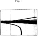
- Said composite shadow image is displayed by said monitoring and evaluating means 7.
- An example of such a displayed composite shadow image is shown in Fig. 11 illustrating, as an object 8, an electrical multi-strand cable in which two of said strands are bent away from the main axis of said cable. Any cables showing such bent-away strands may be identified by said monitoring and evaluating means 7 as cables being improper for subsequent crimping, and therefore to be removed prior to continuation for traveling toward a crimping station.
- said first and second line sensor systems 5 1 , 5 2 constitute a plurality of means for capturing line-shaped images of a fast moving object 8, from different perspectives or viewing angles. Therefore, the aforementioned composite shadow image as illustrated in Fig. 11 represents an image of the object 8 so as having been obtained from an increased viewing angle.
- the same advantage may be achieved if the distance between the first and second sensing positions A 1 , A 2 , is reduced to zero, provided the angles ⁇ 1 and ⁇ 2 are maintained without reduction. This, however, would require more space for accommodating the first and second line sensor systems 5 1 , 5 2 within the housing 1. Thus, crossing of the optical axes of the line sensor systems 5 1 , 5 2 as provided in Figs. 1 to 4 allows reduction of space needed for camera accommodation in the housing 1.
- line images of a moving object 8 are captured at line-shaped sensing positions A 1 , A 2 in a moving plane of the moving object 8, from different sensing angles ⁇ 1 , ⁇ 2 relative to a perpendicular to a moving direction A of the fast moving object 8.
- the line images can be captured in parallel to the respective one of a plurality of line-shaped sensing positions A 1 , A 2 which can be parallel to an elongation of the moving object 8 in the respective sensing position A 1 , A 2 .
- the moving object 8 is illuminated at least from such side of the moving path of the fast moving object 8, which side is opposite to the side directed toward the line sensor systems 5 1 , 5 2 .
- Figs. 5, 6 and 7 are showing a second embodiment of the shape detection device for detecting a moving object, according to the present invention.
- the second embodiment of the shape detection device for a moving object 8 is analogous to the arrangement of the afore-described first embodiment of the shape detection device for a moving object, except that two further line sensor systems 5 3 , 5 4 , which are similar to the line sensor systems 5 1 , 5 2 above, are provided, each having an optical axis inclined in a different sensing angle ⁇ 3 , ⁇ 4 to the moving direction A of the moving object 8.
- a further line sensor system 5 5 is arranged with a line shaped sensing position A 5 which is perpendicular to the moving plane of the moving object 8. Therewith, it is possible to detect a cross section of the moving object 8.
- the viewing angle of the shape detection is further increased in comparison to the first embodiment.
- the two line sensor systems 5 3 and 5 4 produce third and fourth image signals corresponding to third and fourth shadow images from further perspectives of each object 8 or of portions thereof, when the objects 8 are successively passing the third and fourth sensing positions A 3 , A 4 .
- the fifth line sensor system 5 5 produces a fifth image signal which is transmitted to the electronic image composing means 6 to compose a corresponding cross-sectional image of the object 8 when the object 8 successively passes a fifth sensing position A 5 .
- the cross-sectional image is then displayed by said monitoring and evaluating means 7 to detect cables with bent-away strands to be removed prior to being forwarded to a further processing step.
- the method for the operation of the second embodiment of the shape detection device for a moving object 8 of the present invention is analogous to the one described with reference to the first embodiment of the shape detection device except that in the capturing step, further line images are captured at a line shaped sensing position A 5 perpendicular to the moving plane of the fast moving object 8.
- line images of a moving object 8 are captured at line-shaped sensing positions A 1 , A 2, ..., A n in a moving plane of the moving object 8, from different sensing angles ⁇ 1 , ⁇ 2 , ..., ⁇ n relative to a perpendicular to a moving direction A of the fast moving object 8.
- the line images can be captured in parallel to the respective one of a plurality of line-shaped sensing positions A 1 , A 2 , ..., A n which can be parallel to an elongation of the moving object 8 in the respective sensing position A 1 , A 2 , ..., A n .
- Figs. 8 - 10 show a third embodiment of the shape detection device according to the present invention.
- the arrangement of said embodiment is analogous to that of the first embodiment, except that in addition to the two line sensor systems 5 1 , 5 2 and the first illuminating system, two further line sensor systems 5 6 , 5 7 , and a second illuminating system are provided in a reversed arrangement on opposite sides of the moving path of the moving object 8.
- the sensing angles ⁇ 6 , ⁇ 7 of the two further line sensor systems 5 6 , 5 7 are bigger than 90° and smaller than 270°, for detecting line shaped sensing positions A 6 and A 7 .
- each one of said high number of objects 8 when passing through the slit portion 2, passes a sixth sensing position A 6 , a seventh sensing position A 7 , a first sensing position A 1 , and a second sensing position A 2 .
- the second illumination system composed of a light source 10, and a diffusion plate 14 is provided closely above the path of successive movement of the moving object 8 to illuminate the two sensing positions A 6 and A 7 from above.
- illumination systems may be used which illuminate the sensing positions A 1 , A 2 , A 6 and A 7 substantially in the same direction as the photographing direction.
- the two line sensor systems 5 6 and 5 7 have the same construction and are arranged in a similar manner as the ones discussed with reference to the first embodiment. Said line sensor systems 5 6 , 5 7 are producing sixth and seventh shadow images of each of an object 8 are produced on receivers 10 6 and 10 7 , respectively, when said object 8 passes through the sensing positions A 6 , A 7 .
- the light-sensitive receivers 10 6 and 10 7 produce sixth and seventh shadow images of each of the object 8 or of positions thereof, from the side of the moving path which is opposite to the light-sensitive receivers 10 1 , and 10 2 in the first and the second line sensor systems 5 1 , 5 2 , when successively passing said sixth and seventh positions A 6 , A 7 . Therewith, the moving object is detected substantially without a blind angle.
- the method for the operation of the third embodiment of the shape detection device for a moving object 8 of the present invention is analogous to the one described with reference to the first embodiment of the shape detection device.
- n video cameras 5 1 , ..., 5 n may be provided instead of four line sensor systems 5 1 , 5 2 , 5 6 , 5 7 .
- the method of operation is similar to the method of operation of said third embodiment, except that in the capturing step, further line images are captured with a sensing angle ⁇ 1 , ⁇ 2 , ... ⁇ n an bigger than 90° and smaller than 270°.
Landscapes
- Physics & Mathematics (AREA)
- General Physics & Mathematics (AREA)
- Length Measuring Devices By Optical Means (AREA)
- Testing Of Coins (AREA)
- Image Analysis (AREA)
Priority Applications (4)
| Application Number | Priority Date | Filing Date | Title |
|---|---|---|---|
| DE69710591T DE69710591T2 (de) | 1997-11-07 | 1997-11-07 | Einrichtung zur Formerfassung und Verfahren zur Erfassung der Form eines sich bewegenden Objekts |
| EP97119498A EP0922931B1 (de) | 1997-11-07 | 1997-11-07 | Einrichtung zur Formerfassung und Verfahren zur Erfassung der Form eines sich bewegenden Objekts |
| ES97119498T ES2169311T3 (es) | 1997-11-07 | 1997-11-07 | Dispositivo de deteccion de forma y metodo para detectar la forma de un objeto en movimiento. |
| AT97119498T ATE213536T1 (de) | 1997-11-07 | 1997-11-07 | Einrichtung zur formerfassung und verfahren zur erfassung der form eines sich bewegenden objekts |
Applications Claiming Priority (1)
| Application Number | Priority Date | Filing Date | Title |
|---|---|---|---|
| EP97119498A EP0922931B1 (de) | 1997-11-07 | 1997-11-07 | Einrichtung zur Formerfassung und Verfahren zur Erfassung der Form eines sich bewegenden Objekts |
Publications (2)
| Publication Number | Publication Date |
|---|---|
| EP0922931A1 true EP0922931A1 (de) | 1999-06-16 |
| EP0922931B1 EP0922931B1 (de) | 2002-02-20 |
Family
ID=8227588
Family Applications (1)
| Application Number | Title | Priority Date | Filing Date |
|---|---|---|---|
| EP97119498A Expired - Lifetime EP0922931B1 (de) | 1997-11-07 | 1997-11-07 | Einrichtung zur Formerfassung und Verfahren zur Erfassung der Form eines sich bewegenden Objekts |
Country Status (4)
| Country | Link |
|---|---|
| EP (1) | EP0922931B1 (de) |
| AT (1) | ATE213536T1 (de) |
| DE (1) | DE69710591T2 (de) |
| ES (1) | ES2169311T3 (de) |
Cited By (2)
| Publication number | Priority date | Publication date | Assignee | Title |
|---|---|---|---|---|
| EP1391689A1 (de) * | 2002-08-16 | 2004-02-25 | Komax Holding Ag | Einrichtung und Verfahren zum Detektieren von Tüllen |
| WO2017188171A1 (ja) * | 2016-04-26 | 2017-11-02 | 住友電装株式会社 | 電線の露出芯線部の検査装置 |
Citations (5)
| Publication number | Priority date | Publication date | Assignee | Title |
|---|---|---|---|---|
| GB2141542A (en) * | 1983-06-14 | 1984-12-19 | Hauni Werke Koerber & Co Kg | Cigarette testing apparatus |
| JPS61133844A (ja) * | 1984-12-03 | 1986-06-21 | Shin Meiwa Ind Co Ltd | 端子圧着電線の端子圧着部検査方法 |
| JPS61253410A (ja) * | 1985-05-02 | 1986-11-11 | Pilot Pen Co Ltd:The | 物品の輪かく測定方法 |
| US4775235A (en) * | 1984-06-08 | 1988-10-04 | Robotic Vision Systems, Inc. | Optical spot scanning system for use in three-dimensional object inspection |
| EP0676635A1 (de) * | 1994-04-08 | 1995-10-11 | Owens-Brockway Glass Container Inc. | Prüfung von durchsichtigen Behältern |
-
1997
- 1997-11-07 AT AT97119498T patent/ATE213536T1/de not_active IP Right Cessation
- 1997-11-07 DE DE69710591T patent/DE69710591T2/de not_active Expired - Fee Related
- 1997-11-07 EP EP97119498A patent/EP0922931B1/de not_active Expired - Lifetime
- 1997-11-07 ES ES97119498T patent/ES2169311T3/es not_active Expired - Lifetime
Patent Citations (5)
| Publication number | Priority date | Publication date | Assignee | Title |
|---|---|---|---|---|
| GB2141542A (en) * | 1983-06-14 | 1984-12-19 | Hauni Werke Koerber & Co Kg | Cigarette testing apparatus |
| US4775235A (en) * | 1984-06-08 | 1988-10-04 | Robotic Vision Systems, Inc. | Optical spot scanning system for use in three-dimensional object inspection |
| JPS61133844A (ja) * | 1984-12-03 | 1986-06-21 | Shin Meiwa Ind Co Ltd | 端子圧着電線の端子圧着部検査方法 |
| JPS61253410A (ja) * | 1985-05-02 | 1986-11-11 | Pilot Pen Co Ltd:The | 物品の輪かく測定方法 |
| EP0676635A1 (de) * | 1994-04-08 | 1995-10-11 | Owens-Brockway Glass Container Inc. | Prüfung von durchsichtigen Behältern |
Non-Patent Citations (2)
| Title |
|---|
| PATENT ABSTRACTS OF JAPAN vol. 010, no. 327 (P - 513) 7 November 1986 (1986-11-07) * |
| PATENT ABSTRACTS OF JAPAN vol. 011, no. 103 (P - 562) 2 April 1987 (1987-04-02) * |
Cited By (2)
| Publication number | Priority date | Publication date | Assignee | Title |
|---|---|---|---|---|
| EP1391689A1 (de) * | 2002-08-16 | 2004-02-25 | Komax Holding Ag | Einrichtung und Verfahren zum Detektieren von Tüllen |
| WO2017188171A1 (ja) * | 2016-04-26 | 2017-11-02 | 住友電装株式会社 | 電線の露出芯線部の検査装置 |
Also Published As
| Publication number | Publication date |
|---|---|
| DE69710591T2 (de) | 2002-10-10 |
| DE69710591D1 (de) | 2002-03-28 |
| ATE213536T1 (de) | 2002-03-15 |
| ES2169311T3 (es) | 2002-07-01 |
| EP0922931B1 (de) | 2002-02-20 |
Similar Documents
| Publication | Publication Date | Title |
|---|---|---|
| EP1016028B1 (de) | Verfahren und system zum darstellen eines objektes oder musters | |
| WO2001073375A1 (en) | Displacement sensor | |
| US6885400B1 (en) | CCD imaging device and method for high speed profiling | |
| CN1547666A (zh) | 一种用于在自动化过程控制工件检查应用中提供热红外成像快照动作的装置及方法 | |
| CN101115154A (zh) | 运动检测成像设备 | |
| JPH04267211A (ja) | 固体撮像装置 | |
| CN1266994C (zh) | 测量电子元件中触点位置的方法和设备 | |
| JPH08210990A (ja) | 対象物の検査方法および装置 | |
| US6393141B1 (en) | Apparatus for surface image sensing and surface inspection of three-dimensional structures | |
| US6437335B1 (en) | High speed scanner using multiple sensing devices | |
| JPH1068614A (ja) | 撮像装置 | |
| EP0922931B1 (de) | Einrichtung zur Formerfassung und Verfahren zur Erfassung der Form eines sich bewegenden Objekts | |
| JPH11248643A (ja) | 透明フィルムの異物検査装置 | |
| JPH09293999A (ja) | 部品実装機用画像撮像装置 | |
| JP3887809B2 (ja) | 撮像装置 | |
| KR20140102471A (ko) | 웨이퍼 영상 검사 장치 | |
| JPH08110213A (ja) | 物体の三次元像観測・撮像方法及び撮像装置 | |
| JPS6366445A (ja) | 外観検査装置 | |
| US20040119830A1 (en) | Modular electronic image-capturing system with dual functional modes | |
| KR0138313B1 (ko) | 레이저를 이용한 비접촉식 높이 측정장치 | |
| KR102817003B1 (ko) | 2.5차원 이미지 스캔용 밀착형 이미지 센서 | |
| JPH09304287A (ja) | 外観検査装置 | |
| JPH11241917A (ja) | 板形状の検出方法および装置 | |
| JP2683246B2 (ja) | 欠陥検出方法 | |
| JPS6352003A (ja) | 自動目視装置 |
Legal Events
| Date | Code | Title | Description |
|---|---|---|---|
| PUAI | Public reference made under article 153(3) epc to a published international application that has entered the european phase |
Free format text: ORIGINAL CODE: 0009012 |
|
| 17P | Request for examination filed |
Effective date: 19981111 |
|
| AK | Designated contracting states |
Kind code of ref document: A1 Designated state(s): AT BE CH DE DK ES FI FR GB GR IE IT LI LU MC NL PT SE |
|
| AKX | Designation fees paid |
Free format text: AT BE CH DE DK ES FI FR GB GR IE IT LI LU MC NL PT SE |
|
| GRAG | Despatch of communication of intention to grant |
Free format text: ORIGINAL CODE: EPIDOS AGRA |
|
| GRAG | Despatch of communication of intention to grant |
Free format text: ORIGINAL CODE: EPIDOS AGRA |
|
| GRAH | Despatch of communication of intention to grant a patent |
Free format text: ORIGINAL CODE: EPIDOS IGRA |
|
| GRAH | Despatch of communication of intention to grant a patent |
Free format text: ORIGINAL CODE: EPIDOS IGRA |
|
| REG | Reference to a national code |
Ref country code: GB Ref legal event code: IF02 |
|
| GRAA | (expected) grant |
Free format text: ORIGINAL CODE: 0009210 |
|
| AK | Designated contracting states |
Kind code of ref document: B1 Designated state(s): AT BE CH DE DK ES FI FR GB GR IE IT LI LU MC NL PT SE |
|
| PG25 | Lapsed in a contracting state [announced via postgrant information from national office to epo] |
Ref country code: NL Free format text: LAPSE BECAUSE OF FAILURE TO SUBMIT A TRANSLATION OF THE DESCRIPTION OR TO PAY THE FEE WITHIN THE PRESCRIBED TIME-LIMIT Effective date: 20020220 Ref country code: LI Free format text: LAPSE BECAUSE OF FAILURE TO SUBMIT A TRANSLATION OF THE DESCRIPTION OR TO PAY THE FEE WITHIN THE PRESCRIBED TIME-LIMIT Effective date: 20020220 Ref country code: IT Free format text: LAPSE BECAUSE OF FAILURE TO SUBMIT A TRANSLATION OF THE DESCRIPTION OR TO PAY THE FEE WITHIN THE PRE;WARNING: LAPSES OF ITALIAN PATENTS WITH EFFECTIVE DATE BEFORE 2007 MAY HAVE OCCURRED AT ANY TIME BEFORE 2007. THE CORRECT EFFECTIVE DATE MAY BE DIFFERENT FROM THE ONE RECORDED.SCRIBED TIME-LIMIT Effective date: 20020220 Ref country code: GR Free format text: LAPSE BECAUSE OF FAILURE TO SUBMIT A TRANSLATION OF THE DESCRIPTION OR TO PAY THE FEE WITHIN THE PRESCRIBED TIME-LIMIT Effective date: 20020220 Ref country code: FI Free format text: LAPSE BECAUSE OF FAILURE TO SUBMIT A TRANSLATION OF THE DESCRIPTION OR TO PAY THE FEE WITHIN THE PRESCRIBED TIME-LIMIT Effective date: 20020220 Ref country code: CH Free format text: LAPSE BECAUSE OF FAILURE TO SUBMIT A TRANSLATION OF THE DESCRIPTION OR TO PAY THE FEE WITHIN THE PRESCRIBED TIME-LIMIT Effective date: 20020220 Ref country code: BE Free format text: LAPSE BECAUSE OF FAILURE TO SUBMIT A TRANSLATION OF THE DESCRIPTION OR TO PAY THE FEE WITHIN THE PRESCRIBED TIME-LIMIT Effective date: 20020220 |
|
| REF | Corresponds to: |
Ref document number: 213536 Country of ref document: AT Date of ref document: 20020315 Kind code of ref document: T |
|
| REG | Reference to a national code |
Ref country code: CH Ref legal event code: EP |
|
| REF | Corresponds to: |
Ref document number: 69710591 Country of ref document: DE Date of ref document: 20020328 |
|
| PG25 | Lapsed in a contracting state [announced via postgrant information from national office to epo] |
Ref country code: SE Free format text: LAPSE BECAUSE OF FAILURE TO SUBMIT A TRANSLATION OF THE DESCRIPTION OR TO PAY THE FEE WITHIN THE PRESCRIBED TIME-LIMIT Effective date: 20020520 Ref country code: PT Free format text: LAPSE BECAUSE OF FAILURE TO SUBMIT A TRANSLATION OF THE DESCRIPTION OR TO PAY THE FEE WITHIN THE PRESCRIBED TIME-LIMIT Effective date: 20020520 Ref country code: DK Free format text: LAPSE BECAUSE OF FAILURE TO SUBMIT A TRANSLATION OF THE DESCRIPTION OR TO PAY THE FEE WITHIN THE PRESCRIBED TIME-LIMIT Effective date: 20020520 |
|
| ET | Fr: translation filed |
Owner name: IBM CORPORATION |
|
| REG | Reference to a national code |
Ref country code: ES Ref legal event code: FG2A Ref document number: 2169311 Country of ref document: ES Kind code of ref document: T3 |
|
| NLV1 | Nl: lapsed or annulled due to failure to fulfill the requirements of art. 29p and 29m of the patents act | ||
| REG | Reference to a national code |
Ref country code: CH Ref legal event code: PL |
|
| PG25 | Lapsed in a contracting state [announced via postgrant information from national office to epo] |
Ref country code: LU Free format text: LAPSE BECAUSE OF NON-PAYMENT OF DUE FEES Effective date: 20021107 Ref country code: IE Free format text: LAPSE BECAUSE OF NON-PAYMENT OF DUE FEES Effective date: 20021107 |
|
| PLBE | No opposition filed within time limit |
Free format text: ORIGINAL CODE: 0009261 |
|
| STAA | Information on the status of an ep patent application or granted ep patent |
Free format text: STATUS: NO OPPOSITION FILED WITHIN TIME LIMIT |
|
| 26N | No opposition filed |
Effective date: 20021121 |
|
| PG25 | Lapsed in a contracting state [announced via postgrant information from national office to epo] |
Ref country code: MC Free format text: LAPSE BECAUSE OF NON-PAYMENT OF DUE FEES Effective date: 20030601 |
|
| REG | Reference to a national code |
Ref country code: IE Ref legal event code: MM4A |
|
| PGFP | Annual fee paid to national office [announced via postgrant information from national office to epo] |
Ref country code: GB Payment date: 20031112 Year of fee payment: 7 |
|
| PGFP | Annual fee paid to national office [announced via postgrant information from national office to epo] |
Ref country code: ES Payment date: 20031126 Year of fee payment: 7 |
|
| PGFP | Annual fee paid to national office [announced via postgrant information from national office to epo] |
Ref country code: FR Payment date: 20031128 Year of fee payment: 7 Ref country code: AT Payment date: 20031128 Year of fee payment: 7 |
|
| PG25 | Lapsed in a contracting state [announced via postgrant information from national office to epo] |
Ref country code: GB Free format text: LAPSE BECAUSE OF NON-PAYMENT OF DUE FEES Effective date: 20041107 Ref country code: AT Free format text: LAPSE BECAUSE OF NON-PAYMENT OF DUE FEES Effective date: 20041107 |
|
| PG25 | Lapsed in a contracting state [announced via postgrant information from national office to epo] |
Ref country code: ES Free format text: LAPSE BECAUSE OF NON-PAYMENT OF DUE FEES Effective date: 20041108 |
|
| PGFP | Annual fee paid to national office [announced via postgrant information from national office to epo] |
Ref country code: DE Payment date: 20050422 Year of fee payment: 8 |
|
| GBPC | Gb: european patent ceased through non-payment of renewal fee |
Effective date: 20041107 |
|
| PG25 | Lapsed in a contracting state [announced via postgrant information from national office to epo] |
Ref country code: FR Free format text: LAPSE BECAUSE OF NON-PAYMENT OF DUE FEES Effective date: 20050729 |
|
| REG | Reference to a national code |
Ref country code: FR Ref legal event code: ST |
|
| REG | Reference to a national code |
Ref country code: ES Ref legal event code: FD2A Effective date: 20041108 |
|
| PG25 | Lapsed in a contracting state [announced via postgrant information from national office to epo] |
Ref country code: DE Free format text: LAPSE BECAUSE OF NON-PAYMENT OF DUE FEES Effective date: 20060601 |