EP0923177A2 - Entrée de cable avec écrou d'accouplement - Google Patents
Entrée de cable avec écrou d'accouplement Download PDFInfo
- Publication number
- EP0923177A2 EP0923177A2 EP98123573A EP98123573A EP0923177A2 EP 0923177 A2 EP0923177 A2 EP 0923177A2 EP 98123573 A EP98123573 A EP 98123573A EP 98123573 A EP98123573 A EP 98123573A EP 0923177 A2 EP0923177 A2 EP 0923177A2
- Authority
- EP
- European Patent Office
- Prior art keywords
- outer body
- inner body
- tool
- contact surface
- rotation
- Prior art date
- Legal status (The legal status is an assumption and is not a legal conclusion. Google has not performed a legal analysis and makes no representation as to the accuracy of the status listed.)
- Granted
Links
- 230000008878 coupling Effects 0.000 claims abstract description 42
- 238000010168 coupling process Methods 0.000 claims abstract description 42
- 238000005859 coupling reaction Methods 0.000 claims abstract description 42
- 239000004020 conductor Substances 0.000 claims abstract 2
- 230000003287 optical effect Effects 0.000 claims abstract 2
- 210000002105 tongue Anatomy 0.000 claims description 2
- 230000006378 damage Effects 0.000 description 2
- 230000033228 biological regulation Effects 0.000 description 1
- 230000005540 biological transmission Effects 0.000 description 1
- 230000005764 inhibitory process Effects 0.000 description 1
- 238000003780 insertion Methods 0.000 description 1
- 230000037431 insertion Effects 0.000 description 1
Images
Classifications
-
- H—ELECTRICITY
- H02—GENERATION; CONVERSION OR DISTRIBUTION OF ELECTRIC POWER
- H02G—INSTALLATION OF ELECTRIC CABLES OR LINES, OR OF COMBINED OPTICAL AND ELECTRIC CABLES OR LINES
- H02G3/00—Installations of electric cables or lines or protective tubing therefor in or on buildings, equivalent structures or vehicles
- H02G3/02—Details
- H02G3/06—Joints for connecting lengths of protective tubing or channels, to each other or to casings, e.g. to distribution boxes; Ensuring electrical continuity in the joint
- H02G3/0616—Joints for connecting tubing to casing
- H02G3/0625—Joints for connecting tubing to casing with means for preventing disengagement of conductors
- H02G3/0675—Joints for connecting tubing to casing with means for preventing disengagement of conductors with bolts operating in a direction parallel to the conductors
-
- H—ELECTRICITY
- H02—GENERATION; CONVERSION OR DISTRIBUTION OF ELECTRIC POWER
- H02G—INSTALLATION OF ELECTRIC CABLES OR LINES, OR OF COMBINED OPTICAL AND ELECTRIC CABLES OR LINES
- H02G15/00—Cable fittings
- H02G15/013—Sealing means for cable inlets
-
- H—ELECTRICITY
- H02—GENERATION; CONVERSION OR DISTRIBUTION OF ELECTRIC POWER
- H02G—INSTALLATION OF ELECTRIC CABLES OR LINES, OR OF COMBINED OPTICAL AND ELECTRIC CABLES OR LINES
- H02G15/00—Cable fittings
- H02G15/02—Cable terminations
- H02G15/04—Cable-end sealings
Definitions
- the invention relates to a device for insertion an electrically or optically conductive cable in one corresponding device, a connector or the like Generic term of claim 1 designated in more detail Art.
- the invention is therefore based on the object, a generic To create device in which a loosening the union nut even with low tightening torques Use of a tool requires unscrewing the union nut is not possible by hand.
- the one-way clutch the union nut comes into action when the outer body by hand or using an unsuitable, improperly Tool sitting on the tool contact surface is turned in the opening or loosening direction. Then namely, the inner body of the union nut is carried along not, as a result takes place on the internal thread of the Inner body of the union nut does not screw instead of.
- the appropriate tool which under the tool contact surface of the outer body Holding down the coupling element fits, loosening the Union nut also by overcoming one in the closing direction applied tightening torque possible.
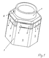
- one Recognized in the view of the entire union nut in FIG. 1 one has an inner body 1 and an outer body 3, the outer body 3 on the inner body 1 is rotatably mounted.
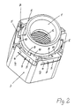
- the inner body 1 has one Union nut usual internal thread 2, which can be seen in Figure 2 is.
- To operate the union nut can be found on the outside of the outer body 3 tool contact surfaces 4, which are key areas for attaching a Fork or a ring spanner.
- a hexagon union nut has the outer body 3 in the circumferential direction six such tool contact surfaces in a regular arrangement, that are each level.
- Figures 1 and 2 coupling elements 5, which as cut or shaped spring tongues are and accordingly in one piece by means of a spring joint 6 are connected to the outer body 3.
- Per tool contact surface 4 is such a coupling element 5, the extends in the circumferential direction of the outer body 3.
- All Coupling elements 5 lie in the direction of a circumferential line of the outer body 3 aligned one behind the other.
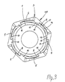
- the coupling elements 5 are parts of a one-way clutch 7, which is a ratchet clutch that is between the outer body 3 and the inner body 1 are arranged is.
- the ratchet members 8 on the inner body 1 are in same number as the coupling elements 5 on the outer body 3 available.
- Coupling elements 5 have on their radially inward side Coupling elements 5 have a sliding surface on their hook heads 10 13, seen in its slope in the circumferential direction to the Slope of a rear flank 14 on the ratchet members 8 is aligned.
- the hook heads dive 10 of the coupling elements 5 in the gaps between the protruding ratchet members 8 on the inner body 1.
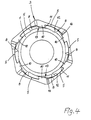
- the outer body 3 is opposed relative to the inner body 1 rotated clockwise, the hook heads 10 run against the Coupling members 5 with their sliding surfaces 13 on the rear Flanks 14 of the ratchet members 8.
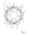
- the radial to internal spring force of the spring joint 6 of the coupling elements 5 is designed so that with the usual inhibition via the internal thread 2 in the screwed-on position of the union nut the inner body 1 the outer body 3 in the direction of rotation counterclockwise does not follow, which is why until reaching the highest in the radial direction Point of the rear flanks 14 of the ratchet members 8 the coupling elements 5 must move radially outwards, which is made clear in Figure 5.
- the coupling elements 5 spring radially inwards back, with the hook heads 10 in the gaps between Submerge the ratchet members 8, then continue turning of the outer body 3 again the radial deflection of the Coupling elements 5 takes place.
- the coupling elements have 5 on the outer body 3 external back surfaces 9 with the tool contact surfaces 4 in a common Level as long as a deflection of the resilient Coupling elements 5 not outwards.
- the Coupling elements due to the emergence of their hook heads 10 on the ratchet members 8 on the inner body 1 to the outside pushed as shown in Figure 5 they are then easily curved back surfaces 9 of the coupling elements 5 in radial Direction clearly above the flat tool contact surfaces 4 to the outside.
- the direction of rotation is in the drawings of the outer body 3 relative to the inner body 1 in a clockwise direction the closing or tightening direction of rotation of the union nut assigned. This always occurs in this direction of rotation entrainment of the inner body 1 by the outer body 3.
- the outer body 3 In the opposite opening or loosening direction the outer body 3 has a freewheel relative to the inner body 1, as long as the described holding down of the coupling elements 5 not done.
- there is in this direction of rotation a rotational driving of the inner body 1 over the outer body 3 only if a properly on the outer body 3 tool attached to the tool contact surfaces 4 its counter surfaces also on the back surfaces 9 of the coupling elements 5 sits and their radial evasion after prevented on the outside.
Landscapes
- Engineering & Computer Science (AREA)
- Architecture (AREA)
- Civil Engineering (AREA)
- Structural Engineering (AREA)
- Cable Accessories (AREA)
- Flexible Shafts (AREA)
- Mechanical Pencils And Projecting And Retracting Systems Therefor, And Multi-System Writing Instruments (AREA)
- Details Of Spanners, Wrenches, And Screw Drivers And Accessories (AREA)
- Clamps And Clips (AREA)
- Laying Of Electric Cables Or Lines Outside (AREA)
- Ropes Or Cables (AREA)
Applications Claiming Priority (2)
| Application Number | Priority Date | Filing Date | Title |
|---|---|---|---|
| DE19755485A DE19755485C1 (de) | 1997-12-13 | 1997-12-13 | Kabeleinführung mit Überwurfmutter |
| DE19755485 | 1997-12-13 |
Publications (3)
| Publication Number | Publication Date |
|---|---|
| EP0923177A2 true EP0923177A2 (fr) | 1999-06-16 |
| EP0923177A3 EP0923177A3 (fr) | 2001-01-10 |
| EP0923177B1 EP0923177B1 (fr) | 2003-01-08 |
Family
ID=7851823
Family Applications (1)
| Application Number | Title | Priority Date | Filing Date |
|---|---|---|---|
| EP98123573A Expired - Lifetime EP0923177B1 (fr) | 1997-12-13 | 1998-12-10 | Entrée de cable avec écrou d'accouplement |
Country Status (3)
| Country | Link |
|---|---|
| EP (1) | EP0923177B1 (fr) |
| AT (1) | ATE230898T1 (fr) |
| DE (2) | DE19755485C1 (fr) |
Cited By (2)
| Publication number | Priority date | Publication date | Assignee | Title |
|---|---|---|---|---|
| WO2004015320A1 (fr) * | 2002-07-27 | 2004-02-19 | Anton Hummel Verwaltungs Gmbh | Garniture de raccordement |
| CN112082133A (zh) * | 2019-06-13 | 2020-12-15 | 华域视觉科技(上海)有限公司 | 一种光导螺母 |
Families Citing this family (1)
| Publication number | Priority date | Publication date | Assignee | Title |
|---|---|---|---|---|
| DE19852100C2 (de) * | 1998-11-12 | 2001-11-22 | Phoenix Contact Gmbh & Co | Kabelanschluß- oder -verbindungseinrichtung |
Family Cites Families (5)
| Publication number | Priority date | Publication date | Assignee | Title |
|---|---|---|---|---|
| DE3336016C1 (de) * | 1983-10-04 | 1985-02-14 | Theodor Heimeier Metallwerk Gmbh, 4782 Erwitte | Diebstahlsicherung für den Thermostatkopf von Heizkörperventilen |
| DE9010310U1 (de) * | 1990-07-07 | 1990-09-13 | OBO Bettermann oHG, 5750 Menden | Vorrichtung aus Kunststoff zur Halterung und Durchführung von Kabeln, Leitungen, Rohren oder Schläuchen |
| US5246379A (en) * | 1992-03-02 | 1993-09-21 | Simmonds Precision Engine Systems, Inc. | Electrical connector and backshell assembly |
| IT1281777B1 (it) * | 1995-04-21 | 1998-03-03 | Raffaele Mongiorgi | Dispositivo per il bloccaggio di organi di connessione, in particolare per apparecchi di saldatura |
| US5653605A (en) * | 1995-10-16 | 1997-08-05 | Woehl; Roger | Locking coupling |
-
1997
- 1997-12-13 DE DE19755485A patent/DE19755485C1/de not_active Expired - Fee Related
-
1998
- 1998-12-10 EP EP98123573A patent/EP0923177B1/fr not_active Expired - Lifetime
- 1998-12-10 DE DE59806859T patent/DE59806859D1/de not_active Expired - Lifetime
- 1998-12-10 AT AT98123573T patent/ATE230898T1/de active
Cited By (4)
| Publication number | Priority date | Publication date | Assignee | Title |
|---|---|---|---|---|
| WO2004015320A1 (fr) * | 2002-07-27 | 2004-02-19 | Anton Hummel Verwaltungs Gmbh | Garniture de raccordement |
| CN100356100C (zh) * | 2002-07-27 | 2007-12-19 | 安东-胡梅尔管理有限公司 | 连接配件 |
| US7338087B2 (en) | 2002-07-27 | 2008-03-04 | Anton Hummel Verwaltungs Gmbh | Connector fitting |
| CN112082133A (zh) * | 2019-06-13 | 2020-12-15 | 华域视觉科技(上海)有限公司 | 一种光导螺母 |
Also Published As
| Publication number | Publication date |
|---|---|
| EP0923177A3 (fr) | 2001-01-10 |
| DE19755485C1 (de) | 1999-08-12 |
| EP0923177B1 (fr) | 2003-01-08 |
| DE59806859D1 (de) | 2003-02-13 |
| ATE230898T1 (de) | 2003-01-15 |
Similar Documents
| Publication | Publication Date | Title |
|---|---|---|
| DE19647742C2 (de) | Einrichtungs-Anziehvorrichtung für unverlierbare Schrauben | |
| DE60014110T2 (de) | Sicherungsvorrichtung | |
| DE4205440C2 (de) | Elektrischer Steckverbinder, insbesondere für Näherungsschalter | |
| EP2240987B1 (fr) | Dispositif a enfichage | |
| DE3507740A1 (de) | Selbstverriegelnde, loesbare verriegelungsmutter | |
| WO2008145435A1 (fr) | Connecteur électrique doté d'un élément d'étanchéité | |
| DE4442075C1 (de) | Schraubverbindung | |
| DE4301504C2 (de) | Elektrischer Steckverbinder | |
| EP0647192B1 (fr) | Adaptateur de roues dentees de bicyclettes | |
| DE3209734A1 (de) | Steckverbinder | |
| EP0357607A1 (fr) | Dispositif permettant de soulager la traction de cables | |
| EP0923177B1 (fr) | Entrée de cable avec écrou d'accouplement | |
| WO1994018731A1 (fr) | Appareil de commande et/ou de signalisation | |
| DE2136500A1 (de) | Hf-koaxialsteckverbindung | |
| DE3829030C2 (de) | Verstellbare Verriegelungsvorrichtung zum Befestigen eines Bauteils an einem anderen Bauteil | |
| DE69319694T2 (de) | Ein Instrument mit einem entfernbaren Deckel | |
| EP1331066B1 (fr) | Clé de serrage d'un dispositif de fixation anti-vol d'une roue de véhicule à un moyeu de roue | |
| DE8107172U1 (de) | Kabelverschraubung | |
| DE69109570T2 (de) | Vorrichtung zum Verbinden von zwei Elementen. | |
| DE4218819C2 (de) | Vorrichtung zur Befestigung eines Gewindeschneidkopfes in einer Gewindeschneidmaschine | |
| DE2827911A1 (de) | Diebstahlsicherung fuer kraftfahrzeug-kennzeichenschilder | |
| DE60317870T2 (de) | Diebstahlsicherung und Sabotageschutzvorrichtung für Reifenventile | |
| DE4443545B4 (de) | Steckverbinder | |
| DE3427591A1 (de) | Schraubenschluessel | |
| DE29510069U1 (de) | Schraubteil von einem Sicherheitsschließsystem |
Legal Events
| Date | Code | Title | Description |
|---|---|---|---|
| PUAI | Public reference made under article 153(3) epc to a published international application that has entered the european phase |
Free format text: ORIGINAL CODE: 0009012 |
|
| AK | Designated contracting states |
Kind code of ref document: A2 Designated state(s): AT CH DE FR IT LI NL |
|
| AX | Request for extension of the european patent |
Free format text: AL;LT;LV;MK;RO;SI |
|
| PUAL | Search report despatched |
Free format text: ORIGINAL CODE: 0009013 |
|
| AK | Designated contracting states |
Kind code of ref document: A3 Designated state(s): AT BE CH CY DE DK ES FI FR GB GR IE IT LI LU MC NL PT SE |
|
| AX | Request for extension of the european patent |
Free format text: AL;LT;LV;MK;RO;SI |
|
| RIC1 | Information provided on ipc code assigned before grant |
Free format text: 7H 02G 15/00 A, 7H 01R 13/621 B, 7H 02G 3/06 B |
|
| 17P | Request for examination filed |
Effective date: 20010620 |
|
| AKX | Designation fees paid |
Free format text: AT CH DE FR IT LI NL |
|
| 17Q | First examination report despatched |
Effective date: 20011127 |
|
| GRAH | Despatch of communication of intention to grant a patent |
Free format text: ORIGINAL CODE: EPIDOS IGRA |
|
| RAP1 | Party data changed (applicant data changed or rights of an application transferred) |
Owner name: PHOENIX CONTACT GMBH & CO. KG |
|
| GRAH | Despatch of communication of intention to grant a patent |
Free format text: ORIGINAL CODE: EPIDOS IGRA |
|
| GRAA | (expected) grant |
Free format text: ORIGINAL CODE: 0009210 |
|
| AK | Designated contracting states |
Kind code of ref document: B1 Designated state(s): AT CH DE FR IT LI NL |
|
| REF | Corresponds to: |
Ref document number: 230898 Country of ref document: AT Date of ref document: 20030115 Kind code of ref document: T |
|
| REG | Reference to a national code |
Ref country code: CH Ref legal event code: EP |
|
| REF | Corresponds to: |
Ref document number: 59806859 Country of ref document: DE Date of ref document: 20030213 Kind code of ref document: P |
|
| REG | Reference to a national code |
Ref country code: CH Ref legal event code: NV Representative=s name: SCHMAUDER & PARTNER AG PATENTANWALTSBUERO |
|
| ET | Fr: translation filed | ||
| PLBE | No opposition filed within time limit |
Free format text: ORIGINAL CODE: 0009261 |
|
| STAA | Information on the status of an ep patent application or granted ep patent |
Free format text: STATUS: NO OPPOSITION FILED WITHIN TIME LIMIT |
|
| 26N | No opposition filed |
Effective date: 20031009 |
|
| REG | Reference to a national code |
Ref country code: CH Ref legal event code: PCAR Free format text: SCHMAUDER & PARTNER AG PATENT- UND MARKENANWAELTE VSP;ZWAENGIWEG 7;8038 ZUERICH (CH) |
|
| PGFP | Annual fee paid to national office [announced via postgrant information from national office to epo] |
Ref country code: CH Payment date: 20121224 Year of fee payment: 15 Ref country code: DE Payment date: 20121210 Year of fee payment: 15 |
|
| PGFP | Annual fee paid to national office [announced via postgrant information from national office to epo] |
Ref country code: IT Payment date: 20121219 Year of fee payment: 15 |
|
| PGFP | Annual fee paid to national office [announced via postgrant information from national office to epo] |
Ref country code: AT Payment date: 20121219 Year of fee payment: 15 |
|
| PGFP | Annual fee paid to national office [announced via postgrant information from national office to epo] |
Ref country code: FR Payment date: 20130117 Year of fee payment: 15 |
|
| PGFP | Annual fee paid to national office [announced via postgrant information from national office to epo] |
Ref country code: NL Payment date: 20121218 Year of fee payment: 15 |
|
| REG | Reference to a national code |
Ref country code: DE Ref legal event code: R119 Ref document number: 59806859 Country of ref document: DE |
|
| REG | Reference to a national code |
Ref country code: NL Ref legal event code: V1 Effective date: 20140701 |
|
| REG | Reference to a national code |
Ref country code: CH Ref legal event code: PL |
|
| REG | Reference to a national code |
Ref country code: AT Ref legal event code: MM01 Ref document number: 230898 Country of ref document: AT Kind code of ref document: T Effective date: 20131210 |
|
| REG | Reference to a national code |
Ref country code: FR Ref legal event code: ST Effective date: 20140829 |
|
| REG | Reference to a national code |
Ref country code: DE Ref legal event code: R119 Ref document number: 59806859 Country of ref document: DE Effective date: 20140701 |
|
| PG25 | Lapsed in a contracting state [announced via postgrant information from national office to epo] |
Ref country code: CH Free format text: LAPSE BECAUSE OF NON-PAYMENT OF DUE FEES Effective date: 20131231 Ref country code: LI Free format text: LAPSE BECAUSE OF NON-PAYMENT OF DUE FEES Effective date: 20131231 Ref country code: DE Free format text: LAPSE BECAUSE OF NON-PAYMENT OF DUE FEES Effective date: 20140701 Ref country code: NL Free format text: LAPSE BECAUSE OF NON-PAYMENT OF DUE FEES Effective date: 20140701 |
|
| PG25 | Lapsed in a contracting state [announced via postgrant information from national office to epo] |
Ref country code: AT Free format text: LAPSE BECAUSE OF NON-PAYMENT OF DUE FEES Effective date: 20131210 Ref country code: FR Free format text: LAPSE BECAUSE OF NON-PAYMENT OF DUE FEES Effective date: 20131231 |
|
| PG25 | Lapsed in a contracting state [announced via postgrant information from national office to epo] |
Ref country code: IT Free format text: LAPSE BECAUSE OF NON-PAYMENT OF DUE FEES Effective date: 20131231 |
|
| PG25 | Lapsed in a contracting state [announced via postgrant information from national office to epo] |
Ref country code: IT Free format text: LAPSE BECAUSE OF NON-PAYMENT OF DUE FEES Effective date: 20131210 |