EP0924022A2 - Endgruppe für Laservorrichtungen, insbesondere zum Schneiden von Blechen - Google Patents
Endgruppe für Laservorrichtungen, insbesondere zum Schneiden von Blechen Download PDFInfo
- Publication number
- EP0924022A2 EP0924022A2 EP98124192A EP98124192A EP0924022A2 EP 0924022 A2 EP0924022 A2 EP 0924022A2 EP 98124192 A EP98124192 A EP 98124192A EP 98124192 A EP98124192 A EP 98124192A EP 0924022 A2 EP0924022 A2 EP 0924022A2
- Authority
- EP
- European Patent Office
- Prior art keywords
- nozzle
- terminal group
- group
- insert
- nozzle carrier
- Prior art date
- Legal status (The legal status is an assumption and is not a legal conclusion. Google has not performed a legal analysis and makes no representation as to the accuracy of the status listed.)
- Withdrawn
Links
Images

Classifications
-
- B—PERFORMING OPERATIONS; TRANSPORTING
- B23—MACHINE TOOLS; METAL-WORKING NOT OTHERWISE PROVIDED FOR
- B23K—SOLDERING OR UNSOLDERING; WELDING; CLADDING OR PLATING BY SOLDERING OR WELDING; CUTTING BY APPLYING HEAT LOCALLY, e.g. FLAME CUTTING; WORKING BY LASER BEAM
- B23K26/00—Working by laser beam, e.g. welding, cutting or boring
- B23K26/14—Working by laser beam, e.g. welding, cutting or boring using a fluid stream, e.g. a jet of gas, in conjunction with the laser beam; Nozzles therefor
- B23K26/1462—Nozzles; Features related to nozzles
- B23K26/1464—Supply to, or discharge from, nozzles of media, e.g. gas, powder, wire
- B23K26/1476—Features inside the nozzle for feeding the fluid stream through the nozzle
Definitions
- the present invention relates to a terminal groups for laser beam devices, in particular for cutting metal sheet, especially of highly reflective material, like e.g. aluminium.
- the most common industrial processing includes drilling, welding and especially cutting of metal sheets, which is also the subject of the present invention.
- the laser devices employed in industrial field produce a beam of perfectly parallel and very intense luminous rays, which are in step with one another (coherent light).
- the beam of rays can be suitably concentrated in a very reduced focus spot, so as to generate therein such a heat power as to cause local melting and evaporation of small metallic masses for every pulse.
- the heat power necessary to provoke local evaporation is a function of the "evaporation heat" parameter.
- the traditional devices for cutting metal sheets include a laser source which is capable of emitting, in the visible or ultraviolet range, a radiation beam of a determined length, frequency and specific power.
- This beam is suitably reflected, by a mirror apparatus, until it is conveyed to a focusing lens.
- this focusing lens is situated inside an axially symmetric group including a nozzle coupled to a suitable nozzle carrier.
- the focused laser ray coaxial with the above described group, is concentrated on a spot of the metal sheet, causing therein localised melting.
- This group has not only to stand the heating action from the laser beam, but also it is struck by a gas flow, which removes the solid and gaseous wastes produced during the processing and cools the working area of the tools.
- the main object of the present invention is to propose a terminal group for laser devices, which can considerably reduce the soiling, and consequent damaging of the focusing lens, or focusing optical group, so as to diminish the replacement necessity for keeping good processing efficiency and high standard operative performance.
- Another object of the present invention is to propose a terminal group for laser devices obtained according to a simple technical solution, and which is extremely functional and reliable, cheap and such as to not cause negative effects on the production process.
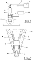
- numeral 1 indicates a source of laser rays, capable of emitting a laser beam 2, which, suitably directed by a conveying section 3, crosses first a first optical focusing group 4, then a terminal group K, and eventually strikes a metal sheet 10, situated substantially perpendicular to the first optical focusing group 4.
- the terminal group K includes a nozzle carrier 7, made of e.g. metal or ceramic material, whose lower part is coupled, by e.g. threading 67a, with a nozzle 6.
- the nozzle 6 is screwed until the nozzle carrier 7 abuts against a first shoulder 67b, made in the external surface of the nozzle 6.
- the upper part of the nozzle carrier 7 is coupled with a support 7a.
- the above mentioned terminal group K features, made therein, an axial through hole 66, inside which a frusto-conical insert 8 is disposed.
- the insert 8 is made preferably of metal or ceramic material and features an axial through hole, whose upper part forms a flange 8a.
- a second optical focusing group 5 e.g. a lens, is disposed in the upper part of the support 7a.
- Means 20 for ejecting washing gas are situated below the second optical focusing group 5.
- Three embodiments of the present invention are proposed, obtained by changing the position of the frusto-conical insert 8 inside the through hole 66 of the terminal group K.
- the terminal group K is formed in such a way that the frusto-conical insert 8 and the nozzle carrier 7 are integral to form one body.
- Figure 2 shows a first embodiment, according to which the flange 8a of the frusto-conical insert 8, situated above the nozzle 6, which is e.g. convergent, is interference or slack fitted into the nozzle carrier 7, which is also e.g. convergent, and abuts against a second shoulder 87 made inside the nozzle carrier 7.
- Figure 3 shows a second embodiment, according to which the upper part of the flange 8a of the frusto-conical insert 8 is in abutments on a third shoulder 68, made in the upper part of the nozzle carrier 7.
- the lower part of the flange 8a rests on a fourth shoulder 69 made in the upper part of the nozzle 6.
- the tip of the nozzle 6 is funnel-shaped.
- Temporal removal of the nozzle 6 causes also the removal of the frusto-conical insert 8, which is withdrawn from the terminal group K keeping in touch with the fourth shoulder 69, until it is completely removed.
- Figure 4 shows a third embodiment, according to which the frusto-conical insert 8 is interference fitted into the nozzle 6, whose terminal parts have truncated cone sections, and is in abutment against the fourth shoulder 69.
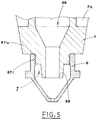
- Figure 5 shows a fourth embodiment, according to which the nozzle carrier 7 has substantially frusto-conical cross-section and is screw coupled to the nozzle 6, e.g. by means of a second threading 67c.
- the nozzle carrier 7 features a protrusion 99.
- the laser beam 2 focused by the lens 5 in a particularly reduced spot of this metal sheet generates local melting of metallic masses, which are removed from the working area by jets of washing gas supplied by the ejection means 20.
- the rapidity and entity of damage of the lens 5 due to this fact depends on the reflexivity of the material which the sheet 10 being processed is made of.
- the narrowing of the terminal parts of the frusto-conical insert 8 or the protrusion 99 allows to correspondingly increase the speed of the gas, ejected by the ejection means 20, in the region of the terminal sections and this consequently reduces the flows of metallic masses returning into the through hole 66.
- the frusto-conical insert 8 performs its action independently from its position inside the through hole 66 of the terminal group K, as shown in Figures 2, 3 and 4, and the bigger the distance between the terminal section of the nozzle 6 and the frusto-conical insert 8 is, the more efficient the action of the insert results.
- the proposed terminal group K guarantees optimal operation of the laser device maintained for long periods, thus reducing the necessity of regular and special maintenance operations and ensuring at the same time considerable throughput and processing efficiency.
- Figure 5 shows an embodiment, according to which the frusto-conical insert 8 is integral with the nozzle carrier 7.
- the frusto-conical insert 8 is integral with the nozzle 6.
Landscapes
- Physics & Mathematics (AREA)
- Optics & Photonics (AREA)
- Engineering & Computer Science (AREA)
- Plasma & Fusion (AREA)
- Mechanical Engineering (AREA)
- Laser Beam Processing (AREA)
- Removal Of Insulation Or Armoring From Wires Or Cables (AREA)
- Manufacturing Of Electrical Connectors (AREA)
Applications Claiming Priority (2)
| Application Number | Priority Date | Filing Date | Title |
|---|---|---|---|
| ITBO970729 | 1997-12-22 | ||
| IT97BO000729A IT1298381B1 (it) | 1997-12-22 | 1997-12-22 | Gruppo terminale per apparecchiature a raggio laser, in particolare per il taglio di lamiere. |
Publications (2)
| Publication Number | Publication Date |
|---|---|
| EP0924022A2 true EP0924022A2 (de) | 1999-06-23 |
| EP0924022A3 EP0924022A3 (de) | 2001-09-12 |
Family
ID=11342703
Family Applications (1)
| Application Number | Title | Priority Date | Filing Date |
|---|---|---|---|
| EP98124192A Withdrawn EP0924022A3 (de) | 1997-12-22 | 1998-12-21 | Endgruppe für Laservorrichtungen, insbesondere zum Schneiden von Blechen |
Country Status (2)
| Country | Link |
|---|---|
| EP (1) | EP0924022A3 (de) |
| IT (1) | IT1298381B1 (de) |
Cited By (3)
| Publication number | Priority date | Publication date | Assignee | Title |
|---|---|---|---|---|
| US7841585B2 (en) | 2003-02-21 | 2010-11-30 | Shell Oil Company | Separation tray |
| CN103192182A (zh) * | 2013-04-18 | 2013-07-10 | 苏州光韵达光电科技有限公司 | 一种用于光纤激光切割陶瓷的喷嘴 |
| CN109718475A (zh) * | 2018-12-19 | 2019-05-07 | 武汉奇致激光技术股份有限公司 | 可调光斑高峰值功率激光输出手具聚焦镜的保护方法 |
Family Cites Families (7)
| Publication number | Priority date | Publication date | Assignee | Title |
|---|---|---|---|---|
| US4121085A (en) * | 1976-05-07 | 1978-10-17 | Caterpillar Tractor Co. | Gas nozzle for laser welding |
| US4774392A (en) * | 1985-04-16 | 1988-09-27 | Amada Engineering & Service Co., Inc. | Laser cutting method for high chromium steel and a device to carry out that method |
| DE3637568A1 (de) * | 1986-11-04 | 1988-05-05 | Trumpf Gmbh & Co | Laser-bearbeitungsmaschine |
| CH673004A5 (de) * | 1987-05-20 | 1990-01-31 | Weidmueller C A Gmbh Co | |
| CN1040514C (zh) * | 1993-10-21 | 1998-11-04 | 三菱电机株式会社 | 加工头及激光加工装置 |
| DE4402000C2 (de) * | 1994-01-25 | 1996-04-11 | Fraunhofer Ges Forschung | Düsenanordnung für das Laserstrahlschneiden |
| DE19627803C1 (de) * | 1996-07-11 | 1997-10-16 | Fraunhofer Ges Forschung | Düsenanordnung zum gleichzeitigen Schweißbearbeiten mit einem Laserstrahl und mit einem Lichtbogen |
-
1997
- 1997-12-22 IT IT97BO000729A patent/IT1298381B1/it active IP Right Grant
-
1998
- 1998-12-21 EP EP98124192A patent/EP0924022A3/de not_active Withdrawn
Cited By (3)
| Publication number | Priority date | Publication date | Assignee | Title |
|---|---|---|---|---|
| US7841585B2 (en) | 2003-02-21 | 2010-11-30 | Shell Oil Company | Separation tray |
| CN103192182A (zh) * | 2013-04-18 | 2013-07-10 | 苏州光韵达光电科技有限公司 | 一种用于光纤激光切割陶瓷的喷嘴 |
| CN109718475A (zh) * | 2018-12-19 | 2019-05-07 | 武汉奇致激光技术股份有限公司 | 可调光斑高峰值功率激光输出手具聚焦镜的保护方法 |
Also Published As
| Publication number | Publication date |
|---|---|
| ITBO970729A1 (it) | 1999-06-22 |
| ITBO970729A0 (it) | 1997-12-22 |
| IT1298381B1 (it) | 2000-01-05 |
| EP0924022A3 (de) | 2001-09-12 |
Similar Documents
| Publication | Publication Date | Title |
|---|---|---|
| US6423928B1 (en) | Gas assisted laser cutting of thin and fragile materials | |
| US4467171A (en) | Laser cutting nozzle | |
| US5477026A (en) | Laser/powdered metal cladding nozzle | |
| US10654129B2 (en) | Laser processing heads with a cross-jet nozzle | |
| UA27963C2 (uk) | Спосіб лазерної обробки робочої заготовки та пристрій для його здійснення | |
| CN102369080A (zh) | 激光加工装置 | |
| US6692337B2 (en) | Laser machining | |
| JP2005088068A (ja) | レーザ加工装置及びレーザ加工工法 | |
| JPH11216589A (ja) | レーザ加工機における光学系部材の汚損防止方法及びその装置 | |
| JP4049844B2 (ja) | レーザ切断加工方法及び装置並びにレーザノズル | |
| CN102186625B (zh) | 用于无切割气体的激光熔化切割的方法 | |
| IT9083400A1 (it) | Dispositivo per un laser di potenza soprattutto per la saldatura | |
| JPH11245077A (ja) | レーザ加工ヘッド | |
| US4684780A (en) | Laser beam focusing head | |
| JP2865543B2 (ja) | レーザ加工ヘッド | |
| JPH11285883A (ja) | 溶接ノズル装置及びレーザ溶接方法 | |
| JPS6027486A (ja) | レ−ザ溶接装置 | |
| JP7202838B2 (ja) | レーザ加工用ノズル及びレーザ加工装置 | |
| JP2002239770A (ja) | レーザ切断用ノズル | |
| US20240091883A1 (en) | Process Monitor for Laser Processing Head | |
| Weberpals et al. | Influence of inclination angle on spatter behavior at welding with lasers of strong focusability | |
| JPS5945475B2 (ja) | レ−ザ加工装置 | |
| JP2000202676A (ja) | レ―ザ加工ヘッド | |
| Volpp et al. | Laser process manipulation by axial beam shaping | |
| CN208342003U (zh) | 一种激光焊接头 |
Legal Events
| Date | Code | Title | Description |
|---|---|---|---|
| PUAI | Public reference made under article 153(3) epc to a published international application that has entered the european phase |
Free format text: ORIGINAL CODE: 0009012 |
|
| AK | Designated contracting states |
Kind code of ref document: A2 Designated state(s): AT BE CH CY DE DK ES FI FR GB GR IE IT LI LU MC NL PT SE |
|
| AX | Request for extension of the european patent |
Free format text: AL;LT;LV;MK;RO;SI |
|
| PUAL | Search report despatched |
Free format text: ORIGINAL CODE: 0009013 |
|
| AK | Designated contracting states |
Kind code of ref document: A3 Designated state(s): AT BE CH CY DE DK ES FI FR GB GR IE IT LI LU MC NL PT SE |
|
| AX | Request for extension of the european patent |
Free format text: AL;LT;LV;MK;RO;SI |
|
| AKX | Designation fees paid | ||
| REG | Reference to a national code |
Ref country code: DE Ref legal event code: 8566 |
|
| STAA | Information on the status of an ep patent application or granted ep patent |
Free format text: STATUS: THE APPLICATION IS DEEMED TO BE WITHDRAWN |
|
| 18D | Application deemed to be withdrawn |
Effective date: 20020313 |