EP0924478A2 - Système frigorifique avec échangeur de chaleur intégré pour le refroidissement d'huile - Google Patents
Système frigorifique avec échangeur de chaleur intégré pour le refroidissement d'huile Download PDFInfo
- Publication number
- EP0924478A2 EP0924478A2 EP98630074A EP98630074A EP0924478A2 EP 0924478 A2 EP0924478 A2 EP 0924478A2 EP 98630074 A EP98630074 A EP 98630074A EP 98630074 A EP98630074 A EP 98630074A EP 0924478 A2 EP0924478 A2 EP 0924478A2
- Authority
- EP
- European Patent Office
- Prior art keywords
- refrigerant
- heat exchanger
- compressor
- cooling
- lubricant
- Prior art date
- Legal status (The legal status is an assumption and is not a legal conclusion. Google has not performed a legal analysis and makes no representation as to the accuracy of the status listed.)
- Withdrawn
Links
Images

Classifications
-
- F—MECHANICAL ENGINEERING; LIGHTING; HEATING; WEAPONS; BLASTING
- F25—REFRIGERATION OR COOLING; COMBINED HEATING AND REFRIGERATION SYSTEMS; HEAT PUMP SYSTEMS; MANUFACTURE OR STORAGE OF ICE; LIQUEFACTION SOLIDIFICATION OF GASES
- F25B—REFRIGERATION MACHINES, PLANTS OR SYSTEMS; COMBINED HEATING AND REFRIGERATION SYSTEMS; HEAT PUMP SYSTEMS
- F25B43/00—Arrangements for separating or purifying gases or liquids; Arrangements for vaporising the residuum of liquid refrigerant, e.g. by heat
- F25B43/006—Accumulators
-
- F—MECHANICAL ENGINEERING; LIGHTING; HEATING; WEAPONS; BLASTING
- F25—REFRIGERATION OR COOLING; COMBINED HEATING AND REFRIGERATION SYSTEMS; HEAT PUMP SYSTEMS; MANUFACTURE OR STORAGE OF ICE; LIQUEFACTION SOLIDIFICATION OF GASES
- F25B—REFRIGERATION MACHINES, PLANTS OR SYSTEMS; COMBINED HEATING AND REFRIGERATION SYSTEMS; HEAT PUMP SYSTEMS
- F25B31/00—Compressor arrangements
- F25B31/002—Lubrication
-
- F—MECHANICAL ENGINEERING; LIGHTING; HEATING; WEAPONS; BLASTING
- F25—REFRIGERATION OR COOLING; COMBINED HEATING AND REFRIGERATION SYSTEMS; HEAT PUMP SYSTEMS; MANUFACTURE OR STORAGE OF ICE; LIQUEFACTION SOLIDIFICATION OF GASES
- F25B—REFRIGERATION MACHINES, PLANTS OR SYSTEMS; COMBINED HEATING AND REFRIGERATION SYSTEMS; HEAT PUMP SYSTEMS
- F25B40/00—Subcoolers, desuperheaters or superheaters
-
- F—MECHANICAL ENGINEERING; LIGHTING; HEATING; WEAPONS; BLASTING
- F25—REFRIGERATION OR COOLING; COMBINED HEATING AND REFRIGERATION SYSTEMS; HEAT PUMP SYSTEMS; MANUFACTURE OR STORAGE OF ICE; LIQUEFACTION SOLIDIFICATION OF GASES
- F25B—REFRIGERATION MACHINES, PLANTS OR SYSTEMS; COMBINED HEATING AND REFRIGERATION SYSTEMS; HEAT PUMP SYSTEMS
- F25B2400/00—Component parts or details not otherwise provided for in this subclass
- F25B2400/05—Compression system with heat exchange between particular parts of the system
- F25B2400/051—Compression system with heat exchange between particular parts of the system between the accumulator and another part of the cycle
-
- F—MECHANICAL ENGINEERING; LIGHTING; HEATING; WEAPONS; BLASTING
- F25—REFRIGERATION OR COOLING; COMBINED HEATING AND REFRIGERATION SYSTEMS; HEAT PUMP SYSTEMS; MANUFACTURE OR STORAGE OF ICE; LIQUEFACTION SOLIDIFICATION OF GASES
- F25B—REFRIGERATION MACHINES, PLANTS OR SYSTEMS; COMBINED HEATING AND REFRIGERATION SYSTEMS; HEAT PUMP SYSTEMS
- F25B2400/00—Component parts or details not otherwise provided for in this subclass
- F25B2400/13—Economisers
Definitions
- This invention is directed to refrigeration systems, and more particularly, to a refrigeration system having an improved oil cooling heat exchanger for lowering the discharge temperature of the compressor thus increasing compressor reliability and for increasing the viscosity of the oil to enhance system performance.
- Conventional air conditioning systems cool air in confined spaces by using four main components, including a compressor, condenser, metering device, and an evaporator. These components also provide the basis for most refrigeration cycles. However, as systems become more technologically advanced, additional components are added.
- the compressor compresses refrigerant gas to a high pressure, high temperature, superheated gaseous state for use by the condenser.
- the condenser in cooling the superheated gas, produces a sub-cooled liquid refrigerant with a high pressure and lower temperature.
- the metering device such as an expansion valve, produces a low temperature, low pressure saturated liquid-vapor mixture from the sub-cooled liquid.
- the evaporator converts the saturated liquid-vapor mixture, to a low temperature, low pressure superheated gas during air cooling for use by the compressor.
- the overall performance and efficiency of refrigeration cycles are directly dependent upon the heat transfer provided by the condenser, evaporator, and compressor oil cooler. The overall performance is further dependent upon the performance and lubrication of the compressor.
- compressors use lubricants which reduce wear and/or seal gaps in the compressor to prevent internal refrigerant leakage.
- compressor efficiency and reliability are increased, providing improved lubricant sealing properties due to increased oil viscosity, improved compressor cooling, and decreased frictional wear.
- screw type compressors utilize counter-rotating rotors to compress refrigerant gas.
- Such compressors rely on lubricants to reduce friction between mating parts and seal gaps between the rotors and crankcase thereof.
- the refrigerant includes some amount of the acquired lubricants before entering the compressor, but some rotating compressor technology injects the oil into the compression process separately.
- refrigerant enters a compressor in vapor form and is compressed, thereby increasing in pressure and temperature.
- the compressor releases the refrigerant and lubricant mixture and the mixture subsequently travels throughout the refrigeration system via a series of closed conduits.
- the refrigerant and lubricant mixture exits the compressor and enters an oil separator.
- the oil is separated from the refrigerant and the refrigerant is routed to a condenser where the heat removal operation via a cooling medium such as outdoor air, occurs on the refrigerant. With heat removed, the refrigerant exits the condenser at high pressure and lower temperature.
- the compressor lubricant flows through an oil cooler, such as a heat exchange apparatus, similar to the condenser, wherein air is the cooling medium.
- the cooled oil flows back to the compressor, functioning to lower the refrigerant discharge temperature and increase the efficiency of the compressor.
- the refrigerant flows from the condenser to the metering device, such as an expansion valve, wherein temperature and pressure of the refrigerant are reduced for subsequent use by the evaporator and results in cooling of the air of the desired space.
- refrigeration cycles such as this may also include an economizer circuit for use in further cooling of the main refrigerant stream. In such cases, an economizer heat exchanger is provided through which the main refrigerant stream passes for cooling.
- a secondary refrigerant flow off-shooting from the main line exiting the condenser is passed through an auxiliary metering device for achieving intermediate pressure and temperature refrigerant.
- This refrigerant is used in further sub-cooling of the main refrigerant flow prior to its passage through the metering device. With the main liquid refrigerant stream cooled in this manner, it can be used in another heat exchange mechanism for further lowering its temperature at the expense of the refrigerant gas traveling from the evaporator to the suction port of the compressor.
- the primary object of this invention is to provide an improved refrigeration system, having a refrigeration cycle with more efficient means for cooling the compressor lubricant.
- the refrigeration system for cooling air includes a substantially liquid refrigerant and an evaporator for transferring heat from the air to the substantially liquid refrigerant.
- the substantially liquid refrigerant becomes a low temperature, low pressure first substantially gaseous refrigerant.
- a compressor compresses the first substantially gaseous refrigerant into a high pressure, high temperature superheated second gaseous refrigerant.
- a lubricant circuit supplies lubricant to the compressor.
- a condenser rejects heat from the second gaseous refrigerant and forms a high pressure, lower temperature sub-cooled liquid refrigerant.
- the condenser has an output stream.
- a metering device transforms the sub-cooled liquid refrigerant into the substantially liquid refrigerant for the evaporator.
- a heat exchanger receives the first substantially gaseous refrigerant as a coolant on route to the compressor.
- the first substantially gaseous refrigerant is relatively cooler than the lubricant and the sub-cooled liquid refrigerant.
- the lubricant via the lubricant circuit flows through the heat exchanger and cools prior to entering the compressor and the sub-cooled liquid refrigerant flowing through the heat exchanger means sub-cools prior to entering the metering device.
- the system includes a sub-cooled liquid refrigerant, which is sub-cooled further by directing it through an accumulator / heat exchanger before entering a metering device.
- a metering device transforms the sub-cooled liquid refrigerant into a substantially liquid, low pressure, low temperature refrigerant mixture which enters an evaporator, where heat transfer from the refrigerated space air to the substantially liquid refrigerant mixture occurs.
- the substantially liquid refrigerant mixture becomes a low temperature, low pressure first saturated refrigerant.
- the first saturated refrigerant enters the accumulator / heat exchanger where it sub-cools the substantially liquid refrigerant headed to the metering device and simultaneously cools the compressor lubricant flow thus becoming a second saturated refrigerant vapor .
- the lubricant circuit carries hot compressor oil out of an oil separator through the accumulator / heat exchanger where its temperature is substantially reduced and returns this cooled lubricant to the compressor.
- the second saturated refrigerant vapor leaves the accumulator / heat exchanger and is supplied to the compressor in superheated gaseous form to start the compression process.
- the compressor compresses the superheated gaseous refrigerant into a high pressure, high temperature further superheated gaseous refrigerant.
- the lubricant and refrigerant gas are mixed together.
- the oil separator extracts oil from the further superheated gaseous refrigerant and directs it to the accumulator / oil cooler. This completes the oil circuit.
- the further superheated gaseous refrigerant enters a condenser, where heat is rejected from it to outdoor air and the further superheated gaseous refrigerant becomes the high pressure, lower temperature sub-cooled liquid. Then this sub-cooled liquid refrigerant stream is split into two flows.
- the main refrigerant flow is directed to the economizer heat exchanger for further sub-cooling and completes the main refrigerant circuit.
- the secondary flow is routed through an auxiliary metering device to become an intermediate pressure, intermediate temperature refrigerant mixture and is used for the main flow sub-cooling in the economizer heat exchanger.
- This refrigerant mixture becomes intermediate pressure, intermediate temperature superheated gas at the economizer heat exchanger outlet and is forwarded to the compressor intermediate pressure port to complete an economizer circuit.
- the system in another embodiment, includes a substantially liquid refrigerant and an evaporator for transferring heat from the air to the substantially liquid refrigerant.
- the substantially liquid refrigerant becomes a low temperature, low pressure first superheated gas refrigerant.
- a compressor compresses the first superheated gas refrigerant into a high pressure, high temperature second further superheated gas refrigerant.
- a lubricant circuit supplies lubricant to the compressor, wherein a portion of the lubricant is mixed with the second superheated gas refrigerant.
- a condenser rejects heat from the second superheated gas refrigerant to form a high pressure, lower temperature sub-cooled liquid refrigerant.
- the condenser has an output stream.
- a metering device transforms the sub-cooled liquid refrigerant from the condenser into the substantially liquid refrigerant for the evaporator.
- An economizer circuit provides an intermediate temperature and pressure economizer refrigerant flow to the compressor.
- the economizer refrigerant flow originates from the output stream of the condenser.
- the economizer circuit includes an economizer heat exchanger.
- the economizer heat exchanger includes paths for receiving and cooling the lubricant before returning to the compressor and the sub-cooled liquid refrigerant on route to the metering device, wherein the economizer refrigerant flow is a cooling medium in the heat exchanger.
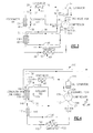
- System 10 generally includes a compressor 12, an oil separator 14, a condenser 16, an integrated accumulator / heat exchanger 18, a metering device 20, an economizer heat exchanger 21, and an evaporator 22.
- the main four elements of a refrigeration system, including the compressor, the condenser, metering device and evaporator are arranged, from a general standpoint, in a manner known in the art for all refrigeration systems.
- Compressor 12 which may be in the form of a screw, rotary, reciprocal or scroll compressor, includes a suction port 23 for receiving a low temperature, low pressure gaseous refrigerant from accumulator/heat exchanger 18. This gaseous refrigerant is compressed in compressor 12 which outputs the high temperature, high pressure superheated gas to oil separator 14 from outlet port 24. Compressor 12 also includes an intermediate port 26 receiving refrigerant sent through an economizer circuit, originating at the output of condenser 16, which is at an intermediate temperature and pressure. The refrigerant exists compressor 12 into oil separator 14, wherein compressor lubricant typically is separated from the refrigerant and then returned to the compressor, as discussed in more detail below.
- the refrigerant then enters condenser 16, wherein the refrigerant is de-superheated, condensed, and sub-cooled through a heat exchange process with ambient air to a lower temperature, high pressure, sub-cooled liquid.
- the liquid refrigerant exits condenser 16 at outlet 28, where it is split into two streams.
- the two streams include the main refrigerant stream 30 and the economizer refrigerant stream 32.
- the economizer refrigerant stream 32 flows through an auxiliary thermal expansion valve 34 and exits valve 34 as economizer stream 36 as an intermediate temperature, intermediate pressure saturated liquid-vapor mixture. This saturated liquid-vapor mixture exiting valve 34 is used as the coolant in economizer heat exchanger 21.
- the main refrigerant stream 30 flows in the opposite direction of the economizer refrigerant stream 36 to provide a counter-flow arrangement for better heat transfer.
- the main refrigerant stream 31 exits heat exchanger 21 at outlet 46 on route to evaporator 22.
- Heat exchanger 21 may be in the form as known in the art and preferably is a brazed plate or tube-in-tube heat exchanger design.
- the refrigerant from outlet 46 flows in stream 31 from heat exchanger 21 into accumulator / heat exchanger 18 for further sub-cooling prior to entering metering device 20.
- the refrigerant is cooled by the low pressure, low temperature, saturated refrigerant exiting evaporator 22 and accumulating in the accumulator for liquid evaporation, on route to compressor 12. Heat exchange with the accumulated refrigerant is facilitated by a first heat exchanger circuit 49.
- First circuit 49 is submerged , as shown in FIG. 2, in the liquid refrigerant secticn 47 in accumulator/heat exchanger 18.
- the refrigerant exits heat exchanger circuit 49 of accumulator / heat exchanger 18 and enters metering device 20, which is preferably in the form of a thermal or electronic expansion valve, and exits the expansion valve as a low temperature and low pressure saturated liquid-vapor mixture.
- the air to be cooled by system 10 flows through evaporator 22 in a heat exchange relationship with the liquid-vapor refrigerant mixture entering evaporator 22 from the metering device 20.
- Refrigerant in evaporator 22 changes from a saturated liquid-vapor mixture state to a saturated substantially gaseous state due to its low boiling temperature and the temperature differential between the lower temperature refrigerant and the air being cooled.
- the saturated substantially gaseous refrigerant exits evaporator 22 in line 50 and flows to the accumulator 18, where any liquid is allowed to boil away before the refrigerant enters the compressor, as indicated above, and flows onward to compressor 12 through suction port 23.
- the accumulator / heat exchanger 18 also cools the oil lubricating compressor 12 .
- the oil is cooled in a unique manner via flow through the accumulator, in a second heat exchanger circuit 51, as the lower temperature saturated gaseous refrigerant accumulates therein. That is, oil flows from oil separator 14 in stream 38 and enters accumulator / heat exchanger 18 at port 52.
- the cooled oil flows through the second heat exchanger circuit 51 of the accumulator with the saturated vapor refrigerant accumulated therein, as described above and is cooled.
- the circuit 51 is positioned in the vapor section 53, as shown in FIG. 2, of accumulator/heat exchanger 18.
- the oil exits accumulator / heat exchanger 18 at port 54 and returns to the compressor through port 44.
- the oil used to lubricate compressor 12 is cooled in a unique manner via accumulator / heat exchanger 18 by a counter-flow arrangement with the coolant therein. That is, through cooling, the oil viscosity is increased, becoming a more efficient friction reducing and more efficient sealing medium as well as allowing for cooler operation of the mechanical components of the compressor, thus increasing its reliability and overall system performance.
- the main stream of refrigerant flows from outlet 46 from economizer heat exchanger 21 into liquid line - suction line heat exchanger (LSHX) 60.
- LSHX 60 is used as the oil cooler in place of the accumulator / heat exchanger 18, prior to the main stream 31 of refrigerant entering evaporator 22.
- the oil or lubricant circuit 62 enters LSHX 60, along with the main refrigerant line exiting heat exchanger 18, each in a counter-flow direction relative to the flow of the low temperature, low pressure superheated refrigerant gas exiting evaporator 22 in line 50.
- both the main refrigerant stream 31 and the oil stream 38 are cooled in LSHX 60, the main refrigerant stream on route to the evaporator and the cooled oil on route to the compressor. Further superheated low temperature, low pressure refrigerant gas is directed to the compressor from LSHX 60, as well.
- the refrigerant in the saturated gaseous state enters the compressor while the compressor is lubricated via cooled oil entering port 44.
- the refrigerant combines with refrigerant from intermediate port 26, exits compressor 12 at outlet 24 and enters oil separator 14. Oil is separated from the refrigerant and returned to compressor 12 after being cooled in accumulator / heat exchanger 18.
- Refrigerant flows from oil separator 14 into condenser 16 and leaves condenser 16 in a lower temperature, high pressure sub-cooled liquid state. The sub-cooled liquid is split into the main refrigerant stream 30 and the economizer stream 32.
- the economizer refrigerant stream 32 flows into an auxiliary thermal expansion valve 34 and leaves valve 34 in stream 36 as an intermediate temperature and intermediate pressure saturated liquid-vapor mixture.
- the refrigerant then flows as stream 36 in this state into economizer heat exchanger 21, acting as the cooling medium for that heat exchanger.
- the refrigerant is returned to compressor 12 through intermediate port 26.
- the main refrigerant stream 30 passes through heat exchanger 21 and is cooled by the refrigerant in economizer stream 36 flowing in a counter-flow arrangement.
- the main refrigerant stream 31 exits heat exchanger 21 in a cooler state on route to accumulator / heat exchanger 18 for sub-cooling in the first, refrigerant-submerged heat exchange circuit 49.
- Oil from oil separator 14, enters accumulator / heat exchanger 18, in the second, vapor positioned heat exchange circuit 51, similar to the refrigerant in main line 31, and is cooled by the accumulated and cooler saturated refrigerant vapor. Oil returns to compressor 12 through port 44 at a lower temperature and higher viscosity for cooling the compressor, achieving improved sealing capabilities and reducing friction among the mechanical components of the compressor .
- the refrigerant flows from economizer heat exchanger 21, is sub-cooled in accumulator / heat exchanger 18, flows through metering device 20, exiting therefrom at a low temperature, low pressure saturated, substantially liquid, liquid-vapor mixture.
- a control device 64 for measuring liquid refrigerant sub-cooling is provided at an outlet of said accumulator and means for controlling liquid refrigerant level in said accumulator. This mixture enters evaporator 22 whereby, as indicated in the beginning, it is boiled through a heat exchange arrangement. Finally, the refrigerant exits evaporator 22 to accumulator / heat exchanger 18, on route to compressor 12, as described.
- the operation of the second embodiment is similar to as described above with the exception that the accumulator performing of the cooling function is replaced by the LSHX performing the cooling function. Accordingly, the main stream of refrigerant exiting economizer heat exchanger 21 enters LSHX 60 along with oil in oil stream 38, originating from oil separator 14.
- the low temperature, low pressure superheated gaseous refrigerant exiting evaporator 22 in line 50 enters LSHX 60 in a counter-flow direction relative the oil from line 62 and main stream of refrigerant from stream 30, as shown in FIG. 2, and functions to cool the same, while on route to the compressor.
- System 110 generally includes a compressor 112, an oil separator 114, a condenser 116, an integrated economizer/oil cooler heat exchanger 118, a metering device 120 and an evaporator 122.
- the main four elements of a refrigeration system, including the compressor, the condenser, metering device and evaporator are arranged, from a general standpoint, in a manner known in the art for all refrigeration systems.
- Compressor 112 which may be in the form of a screw, rotary, reciprocal or scroll compressor, includes a suction port 123 for receiving a low temperature, low pressure superheated gas refrigerant from evaporator 122. This superheated gas refrigerant is compressed in compressor 112 which outputs the high temperature, high pressure superheated gas to oil separator 114 from outlet port 124. Compressor 112 also includes an intermediate port 126 receiving refrigerant sent through an economizer circuit, originating at the output of condenser 116, which is at an intermediate temperature and pressure. The refrigerant exists compressor 112 into oil separator 114, wherein compressor lubricant typically is separated from the refrigerant and then returned to the compressor, as discussed in more detail below.
- the refrigerant then enters condenser 116, wherein the refrigerant is de-superheated, condensed, and sub-cooled through a heat exchange process with ambient air to a lower temperature, high pressure, sub-cooled liquid.
- the liquid refrigerant exits condenser 116 at outlet 128, where it is split into two streams.
- the two streams include the main refrigerant stream 130 and the economizer refrigerant stream 132.
- the economizer refrigerant stream 132 flows through an auxiliary thermal expansion valve 134 and exits valve 134 as economizer stream 136 as an intermediate temperature, intermediate pressure saturated liquid-vapor mixture. This saturated liquid-vapor mixture exiting valve 134 is used as the coolant in heat exchanger 118.
- the main refrigerant stream 130 flows in the opposite direction of the economizer refrigerant stream 136 to provide a counter-flow arrangement.
- oil return line 138 flows into heat exchanger 118 at inlet 140. Since the oil had been processed through compressor 114, the oil is at a higher temperature and pressure than the refrigerant of the economizer stream, which simultaneously flows through heat exchanger 118. Therefore, as the oil flows through heat exchanger 128 in a counter-flow direction to the economizer refrigerant stream 136, the temperature of the oil is substantially reduced.
- the oil flows through line 142 back to an oil return port 144 of compressor 112.
- Heat exchanger 118 may be in the form as known in the art and preferably is a brazed plate or tube-in-tube heat exchanger design.
- the refrigerant from outlet 146 flows from heat exchanger 118 into a liquid line-suction line heat exchanger 148 (LSHX), which is used to further pre-cool refrigerant flowing into evaporator 122 before its heat exchange with the air being cooled by system 110.
- Refrigerant flows from LSHX 148 into metering device 120, which is preferably in the form of a thermal or electronic expansion valve, and exits the expansion valve as a low temperature and low pressure saturated liquid-vapor mixture.
- the air to be cooled by system 110 flows through evaporator 122 in a heat exchange relationship with the liquid-vapor refrigerant mixture entering evaporator 122 from the metering device 120.
- Refrigerant in evaporator 122 changes from a saturated liquid-vapor mixture to a superheated gas due to its low boiling temperature and the temperature differential between the lower temperature refrigerant and the air being cooled.
- the superheated gas refrigerant exits evaporator 122 in line 150 and flows through LSHX 148 for precooling counterflowing refrigerant form heat exchanger 118, prior to its entrance to compressor 112 through suction port 123.
- the oil used to lubricate compressor 112 is cooled in a unique manner via economizer heat exchanger 118 by a counter-flow arrangement with the coolant in the economizer stream circuit. That is, through cooling, the oil viscosity is increased, becoming a more efficient friction reducing medium as well as allowing for cooler operation of the mechanical components of the compressor.
- an economizer oil cooling circuit can be added and the economizer refrigerant will pass through the economizer heat exchanger for achieving the same results as discussed above.
- air to be cooled is forced to pass over or through evaporator 122 for the exchange of heat with refrigerant flowing through the evaporator.
- the refrigerant leaves the evaporator, having absorbed the heat of the air, as a low temperature, low pressure superheated gas.
- the refrigerant flows through LSHX 148 for superheating prior to entering compressor 112.
- the refrigerant in the superheated gaseous state enters the compressor while the compressor is lubricated via cooled oil entering port 144.
- the refrigerant combines with refrigerant from intermediate port 126 and exits compressor 112 at outlet 124 and enters oil separator 114. Oil is separated from the refrigerant and returned to compressor 112 after being cooled in heat exchanger 118.
- Refrigerant flows from oil separator 114 into condenser 16 and leaves condenser 16 in a lower temperature, high pressure sub-cooled liquid state.
- the sub-cooled liquid is split into the main refrigerant stream 130 and the economizer stream 132.
- the economizer refrigerant stream 132 flows into a thermal expansion valve 134 and leaves valve 134 in a low temperature and low pressure saturated liquid-vapor mixture state.
- the refrigerant then flows as stream 136 in this state into heat exchanger 118, acting as the cooling medium for that heat exchanger. After performing cooling in heat exchanger 118, the refrigerant is returned to compressor 112 through intermediate port 126.
- the main refrigerant stream 130 passes through heat exchanger 18 and is cooled by the refrigerant in economizer stream 136 flowing in a counter flow arrangement.
- the main refrigerant stream 130 exits heat exchanger 118 in a cooler state for subsequent cooling in LSHX 148.
- Oil from oil separator 114 enters heat exchanger 118, similar to the main refrigerant stream 130, and is cooled by the counter-flowing refrigerant of the economizer stream 136. Oil returns to compressor 112 through port 144 at a lower temperature and higher viscosity for cooling the compressor, achieving improved sealing capabilities and reducing friction among the mechanical components of the compressor .
- the refrigerant flows from LSHX 148, through metering device 120, exiting therefrom at a low temperature, low pressure saturated, substantially liquid, liquid-vapor mixture.
- This mixture enters evaporator 122 whereby, as indicated in the beginning, it is boiled and then superheated through a heat exchange arrangement.
Landscapes
- Engineering & Computer Science (AREA)
- Physics & Mathematics (AREA)
- Mechanical Engineering (AREA)
- Thermal Sciences (AREA)
- General Engineering & Computer Science (AREA)
- Chemical & Material Sciences (AREA)
- Analytical Chemistry (AREA)
- Power Engineering (AREA)
- Applications Or Details Of Rotary Compressors (AREA)
- Devices That Are Associated With Refrigeration Equipment (AREA)
Applications Claiming Priority (4)
| Application Number | Priority Date | Filing Date | Title |
|---|---|---|---|
| US994224 | 1992-12-21 | ||
| US991588 | 1997-12-15 | ||
| US08/991,588 US5899091A (en) | 1997-12-15 | 1997-12-15 | Refrigeration system with integrated economizer/oil cooler |
| US08/994,224 US6058727A (en) | 1997-12-19 | 1997-12-19 | Refrigeration system with integrated oil cooling heat exchanger |
Publications (2)
| Publication Number | Publication Date |
|---|---|
| EP0924478A2 true EP0924478A2 (fr) | 1999-06-23 |
| EP0924478A3 EP0924478A3 (fr) | 2000-03-22 |
Family
ID=27130657
Family Applications (1)
| Application Number | Title | Priority Date | Filing Date |
|---|---|---|---|
| EP98630074A Withdrawn EP0924478A3 (fr) | 1997-12-15 | 1998-12-11 | Système frigorifique avec échangeur de chaleur intégré pour le refroidissement d'huile |
Country Status (1)
| Country | Link |
|---|---|
| EP (1) | EP0924478A3 (fr) |
Cited By (16)
| Publication number | Priority date | Publication date | Assignee | Title |
|---|---|---|---|---|
| EP1202003A3 (fr) * | 2000-10-31 | 2002-10-16 | Modine Manufacturing Company | Système frigorifique avec séparation de phases |
| EP1696188A3 (fr) * | 2005-01-31 | 2008-02-13 | Sanyo Electric Co., Ltd. | Dispositif de réfrigération et réfrigérateur |
| EP1862749A3 (fr) * | 2006-05-30 | 2008-12-24 | Sanden Corporation | Cycle frigorifique à compression de vapeur |
| CN101900113A (zh) * | 2009-05-15 | 2010-12-01 | 艾默生环境优化技术有限公司 | 压缩机和油冷却系统 |
| CN102914102A (zh) * | 2011-08-05 | 2013-02-06 | 珠海格力电器股份有限公司 | 螺杆式盐水机组 |
| WO2013063668A1 (fr) * | 2011-11-01 | 2013-05-10 | Whirlpool S.A. | Système de réfrigération |
| US8590324B2 (en) | 2009-05-15 | 2013-11-26 | Emerson Climate Technologies, Inc. | Compressor and oil-cooling system |
| EP2383529A4 (fr) * | 2009-01-27 | 2014-07-02 | Mitsubishi Electric Corp | Climatiseur et procédé de retour de l'huile de machine frigorifique |
| CN105324616A (zh) * | 2013-06-17 | 2016-02-10 | 开利公司 | 制冷系统的油料回收 |
| CN105823256A (zh) * | 2016-03-22 | 2016-08-03 | 东南大学 | 一种压缩机回油冷却的空气源热泵装置的工作方法 |
| CN108800685A (zh) * | 2018-08-22 | 2018-11-13 | 安徽美乐柯制冷空调设备有限公司 | 一种设有过冷器和润滑油冷却器的冷水机组 |
| WO2020227374A3 (fr) * | 2019-05-07 | 2020-12-17 | Carrier Corporation | Échangeur de chaleur combiné, système d'échange de chaleur et son procédé d'optimisation |
| CN114353379A (zh) * | 2021-12-22 | 2022-04-15 | 天普新能源科技有限公司 | 一种带有润滑油余热回收功能的二氧化碳热泵系统 |
| CN115164411A (zh) * | 2022-09-08 | 2022-10-11 | 江苏荣亿达温控科技有限公司 | 一种基于物联网智能控制的温控一体机控制系统及其方法 |
| CN118009592A (zh) * | 2024-04-09 | 2024-05-10 | 珠海格力电器股份有限公司 | 一种回油装置、回油控制方法及制冷系统 |
| WO2025261426A1 (fr) * | 2024-06-21 | 2025-12-26 | 阿特拉斯·科普柯(无锡)压缩机有限公司 | Unité de pompe à chaleur et système d'utilisation d'énergie thermique |
Family Cites Families (10)
| Publication number | Priority date | Publication date | Assignee | Title |
|---|---|---|---|---|
| US2385667A (en) * | 1944-08-24 | 1945-09-25 | Robert C Webber | Refrigerating system |
| US3830077A (en) * | 1972-07-20 | 1974-08-20 | H Willen | Heat exchanger for connection in evaporator-to-compressor line of air conditioner |
| US4208887A (en) * | 1979-01-22 | 1980-06-24 | Tecumseh Products Company | Suction accumulator having heat exchanger |
| US4217765A (en) * | 1979-06-04 | 1980-08-19 | Atlantic Richfield Company | Heat exchanger-accumulator |
| SE460223B (sv) * | 1987-07-17 | 1989-09-18 | Sigurd Hultgren | Trippelroervaermevaexlare med till denna kopplad foerraadsvolym foer varmvatten ansluten till fjaerrvaermenaet |
| US4850197A (en) * | 1988-10-21 | 1989-07-25 | Thermo King Corporation | Method and apparatus for operating a refrigeration system |
| US5245833A (en) * | 1992-05-19 | 1993-09-21 | Martin Marietta Energy Systems, Inc. | Liquid over-feeding air conditioning system and method |
| BR9307842A (pt) * | 1993-03-31 | 1996-01-02 | American Standard Inc | Resfriamento de lubrificante de compressor em um sistema de refrigeração |
| US5408836A (en) * | 1994-01-14 | 1995-04-25 | Thermo King Corporation | Methods and apparatus for operating a refrigeration system characterized by controlling engine coolant |
| SE504799C2 (sv) * | 1995-08-23 | 1997-04-28 | Swep International Ab | Trekrets-värmeväxlare |
-
1998
- 1998-12-11 EP EP98630074A patent/EP0924478A3/fr not_active Withdrawn
Cited By (24)
| Publication number | Priority date | Publication date | Assignee | Title |
|---|---|---|---|---|
| EP1202003A3 (fr) * | 2000-10-31 | 2002-10-16 | Modine Manufacturing Company | Système frigorifique avec séparation de phases |
| EP1696188A3 (fr) * | 2005-01-31 | 2008-02-13 | Sanyo Electric Co., Ltd. | Dispositif de réfrigération et réfrigérateur |
| EP1862749A3 (fr) * | 2006-05-30 | 2008-12-24 | Sanden Corporation | Cycle frigorifique à compression de vapeur |
| EP2383529A4 (fr) * | 2009-01-27 | 2014-07-02 | Mitsubishi Electric Corp | Climatiseur et procédé de retour de l'huile de machine frigorifique |
| US9115917B2 (en) | 2009-01-27 | 2015-08-25 | Mitsubishi Electric Corporation | Air-conditioner and method of returning and cooling compressor oil |
| US9316227B2 (en) | 2009-05-15 | 2016-04-19 | Emerson Climate Technologies, Inc. | Compressor and oil-cooling system |
| CN101900113A (zh) * | 2009-05-15 | 2010-12-01 | 艾默生环境优化技术有限公司 | 压缩机和油冷却系统 |
| CN101900113B (zh) * | 2009-05-15 | 2013-10-30 | 艾默生环境优化技术有限公司 | 压缩机和油冷却系统 |
| US8590324B2 (en) | 2009-05-15 | 2013-11-26 | Emerson Climate Technologies, Inc. | Compressor and oil-cooling system |
| CN102914102A (zh) * | 2011-08-05 | 2013-02-06 | 珠海格力电器股份有限公司 | 螺杆式盐水机组 |
| WO2013063668A1 (fr) * | 2011-11-01 | 2013-05-10 | Whirlpool S.A. | Système de réfrigération |
| US20160153688A1 (en) * | 2013-06-17 | 2016-06-02 | Carrier Corporation | Oil recovery for refrigeration system |
| CN105324616A (zh) * | 2013-06-17 | 2016-02-10 | 开利公司 | 制冷系统的油料回收 |
| CN105324616B (zh) * | 2013-06-17 | 2019-05-03 | 开利公司 | 制冷系统的油料回收 |
| US10408508B2 (en) * | 2013-06-17 | 2019-09-10 | Carrier Corporation | Oil recovery for refrigeration system |
| CN105823256A (zh) * | 2016-03-22 | 2016-08-03 | 东南大学 | 一种压缩机回油冷却的空气源热泵装置的工作方法 |
| CN108800685A (zh) * | 2018-08-22 | 2018-11-13 | 安徽美乐柯制冷空调设备有限公司 | 一种设有过冷器和润滑油冷却器的冷水机组 |
| WO2020227374A3 (fr) * | 2019-05-07 | 2020-12-17 | Carrier Corporation | Échangeur de chaleur combiné, système d'échange de chaleur et son procédé d'optimisation |
| US11662125B2 (en) | 2019-05-07 | 2023-05-30 | Carrier Corporation | Combined heat exchanger, heat exchanging system and the optimization method thereof |
| US12498150B2 (en) | 2019-05-07 | 2025-12-16 | Carrier Corporation | Combined heat exchanger, heat exchanging system and the optimization method thereof |
| CN114353379A (zh) * | 2021-12-22 | 2022-04-15 | 天普新能源科技有限公司 | 一种带有润滑油余热回收功能的二氧化碳热泵系统 |
| CN115164411A (zh) * | 2022-09-08 | 2022-10-11 | 江苏荣亿达温控科技有限公司 | 一种基于物联网智能控制的温控一体机控制系统及其方法 |
| CN118009592A (zh) * | 2024-04-09 | 2024-05-10 | 珠海格力电器股份有限公司 | 一种回油装置、回油控制方法及制冷系统 |
| WO2025261426A1 (fr) * | 2024-06-21 | 2025-12-26 | 阿特拉斯·科普柯(无锡)压缩机有限公司 | Unité de pompe à chaleur et système d'utilisation d'énergie thermique |
Also Published As
| Publication number | Publication date |
|---|---|
| EP0924478A3 (fr) | 2000-03-22 |
Similar Documents
| Publication | Publication Date | Title |
|---|---|---|
| US6058727A (en) | Refrigeration system with integrated oil cooling heat exchanger | |
| US5899091A (en) | Refrigeration system with integrated economizer/oil cooler | |
| EP0924478A2 (fr) | Système frigorifique avec échangeur de chaleur intégré pour le refroidissement d'huile | |
| US9851130B2 (en) | Electronics cooling using lubricant return for a shell-and-tube style evaporator | |
| US3710590A (en) | Refrigerant cooled oil system for a rotary screw compressor | |
| US5570583A (en) | Cooling of compressor lubricant in a refrigeration system | |
| US6425249B1 (en) | High efficiency refrigeration system | |
| KR100408960B1 (ko) | 다단 압축식 냉동기 | |
| US9032754B2 (en) | Electronics cooling using lubricant return for a shell-and-tube evaporator | |
| KR101633781B1 (ko) | 칠러 | |
| US3856493A (en) | Energy recovery system for oil injected screw compressors | |
| GB2446062A (en) | Carbon dioxide refrigeration system with compressors in two-stage arrangement | |
| MXPA01010444A (es) | Sistema de refrigeracion con sdeparacion de fase.. | |
| JPH01111179A (ja) | 流下液膜式蒸発器 | |
| JP2001272122A (ja) | 二段圧縮冷凍機 | |
| JPH03105160A (ja) | スクリュー冷凍機 | |
| WO2001067011A1 (fr) | Systeme frigorifique haute efficacite | |
| JPS6022250B2 (ja) | 蒸気圧縮冷凍装置 | |
| JP2008241195A (ja) | 冷凍装置 | |
| JP3565477B2 (ja) | 圧縮式冷凍機 | |
| RU2238486C2 (ru) | Холодильная система | |
| JPH11325648A (ja) | エンジン駆動の圧縮式冷凍機 | |
| JPH02287059A (ja) | 冷凍サイクル | |
| JP3286723B2 (ja) | 複数台の圧縮機を搭載したマルチ冷凍機における油冷却器 | |
| JPH1151510A (ja) | 蒸発器 |
Legal Events
| Date | Code | Title | Description |
|---|---|---|---|
| PUAI | Public reference made under article 153(3) epc to a published international application that has entered the european phase |
Free format text: ORIGINAL CODE: 0009012 |
|
| AK | Designated contracting states |
Kind code of ref document: A2 Designated state(s): DE FR GB NL |
|
| AX | Request for extension of the european patent |
Free format text: AL;LT;LV;MK;RO;SI |
|
| PUAL | Search report despatched |
Free format text: ORIGINAL CODE: 0009013 |
|
| AK | Designated contracting states |
Kind code of ref document: A3 Designated state(s): AT BE CH CY DE DK ES FI FR GB GR IE IT LI LU MC NL PT SE |
|
| AX | Request for extension of the european patent |
Free format text: AL;LT;LV;MK;RO;SI |
|
| RIC1 | Information provided on ipc code assigned before grant |
Free format text: 7F 25B 1/00 A, 7F 25B 5/02 B, 7F 25B 31/00 B, 7F 25B 40/00 B, 7F 25B 43/00 B |
|
| 17P | Request for examination filed |
Effective date: 20000826 |
|
| AKX | Designation fees paid |
Free format text: DE FR GB NL |
|
| GRAH | Despatch of communication of intention to grant a patent |
Free format text: ORIGINAL CODE: EPIDOS IGRA |
|
| STAA | Information on the status of an ep patent application or granted ep patent |
Free format text: STATUS: THE APPLICATION IS DEEMED TO BE WITHDRAWN |
|
| 18D | Application deemed to be withdrawn |
Effective date: 20030226 |