EP0924509A2 - Procédé et dispositif pour détecter l'écoulement de segments liquides et gazeux à travers un tube - Google Patents
Procédé et dispositif pour détecter l'écoulement de segments liquides et gazeux à travers un tube Download PDFInfo
- Publication number
- EP0924509A2 EP0924509A2 EP98123778A EP98123778A EP0924509A2 EP 0924509 A2 EP0924509 A2 EP 0924509A2 EP 98123778 A EP98123778 A EP 98123778A EP 98123778 A EP98123778 A EP 98123778A EP 0924509 A2 EP0924509 A2 EP 0924509A2
- Authority
- EP
- European Patent Office
- Prior art keywords
- tube
- light
- fiber optic
- liquid
- output
- Prior art date
- Legal status (The legal status is an assumption and is not a legal conclusion. Google has not performed a legal analysis and makes no representation as to the accuracy of the status listed.)
- Withdrawn
Links
Images


Classifications
-
- G—PHYSICS
- G01—MEASURING; TESTING
- G01N—INVESTIGATING OR ANALYSING MATERIALS BY DETERMINING THEIR CHEMICAL OR PHYSICAL PROPERTIES
- G01N21/00—Investigating or analysing materials by the use of optical means, i.e. using sub-millimetre waves, infrared, visible or ultraviolet light
- G01N21/17—Systems in which incident light is modified in accordance with the properties of the material investigated
- G01N21/41—Refractivity; Phase-affecting properties, e.g. optical path length
Definitions
- the present invention is directed to a method and apparatus for discriminating between liquid and gas in a stream of liquid and gas segments flowing through an elongated tube and for sensing the direction of flow of such a segmented stream.
- the present invention is also directed to a method and apparatus for detecting the presence of a liquid segment in such a segmented stream which contains a marker dye having known absorbance characteristics.
- liquid samples such as blood plasma or urine are often processed by separating each of a number of samples by a gas bubble, typically air, to create a stream of segments and flowing the stream of liquid and gas segments through an elongated tube. As the stream flows through the tube, various analytical measurements are performed. In some systems, the flow of the stream of liquid and gas segments is capable of reversing direction during processing.
- a gas bubble typically air
- Figs. 1 and 2 are schematic cross-section diagrams of the above-described prior art bubble detector described in the '946 patent.
- the bubble detector includes an illumination fiber optic bundle 10 which receives white input light from light source 11 and directs the light through the diameter of a transparent tube 12 through which a liquid and gas segmented stream passes in a direction orthogonal to the longitudinal axis of the tube 12.
- Located on the side of the tube 12 opposite bundle 10 is a collection fiber optic bundle 14, which directs light to conventional analyzer instrumentation (not shown), and a smaller fiber optic bundle 15.
- Bundle 15 only receives light extending outside a predetermined zone in which bundle 14 is disposed.
- the light collected by bundle 15 is input into a photodiode 16 that converts the light to electrical energy.
- Comparator 17 compares the output of the photodiode 16 to a reference voltage 18 and generates a control signal 19.
- the light from the illumination fiber optic bundle 10 is bent or refracted when passing through the liquid filled tube 12 so that substantially none of the light rays extend outside the predetermined zone and reach bundle 15.
- the signal from the photodiode 16 is low, i.e., below the reference voltage 18, so that the comparator 17 produces a control signal 19 having a first level which indicates that there is liquid in the tube 12.
- the tube 12 contains a gas such as air
- the light rays from the illumination fiber optic bundle 10 are not refracted or bent as severely, and consequently, a significant portion of the light is disposed beyond the predetermined zone and is collected by the bundle 15.
- the signal from the photodiode 16 is high, i.e., above the reference voltage 18, so that the comparator 17 produces a control signal 19 having a second level that indicates that a gas is in the tube 12.
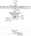
- Fig. 3 shows another embodiment of the bubble detector described in the '946 patent wherein the direction of flow of a stream of liquid and gas segments is detected in addition to the detection of a liquid/gas interface.
- the bubble detector includes two light path channels made up of fiber optic bundles 15 and 15' that share the same illumination fiber bundle 10.
- the bundles 15 and 15' are spaced apart a distance less than the width of the smallest liquid or gas segment in order to detect the interface between a gas segment and a liquid segment.
- each of the bundles 15 and 15' is fed to photodiodes 16 and 16', the outputs of which are received by comparators 17 and 17' and compared to reference voltages 18 and 18' to produce outputs 19 and 19'.
- the outputs 19 and 19' are applied to logic circuit 20 which produces two output signals 21 and 22, one specifying the fact that a liquid/gas interface has occurred and the other specifying the direction of flow of the stream.
- the particulars of the logic circuit 20, and the method utilized therein to determine the direction of flow of the stream are described fully in the '946 patent and will not be repeated herein.
- the bubble detector described in the '946 patent utilizes a single light source 11 and a single illumination fiber optic bundle 10 to direct light through tube 12 for each of the two light path channels, and because the light travels in substantially the same direction in each of the light path channels, there is a tendency for optical cross-talk to occur between the two channels. As a result, some of the light from the first channel may be received by the photodiode dedicated to the second channel and vice versa, thereby creating a signal discrimination problem.
- the present invention relates to a method and apparatus for detecting the presence of a liquid segment and a gas segment in a stream of liquid and gas segments flowing through an elongated transparent tube and for sensing a direction of flow of the stream in the tube.
- One aspect of the invention is directed to a bubble detector/direction sensor.
- One such sensor includes first and second light sources, first and second input fiber optic bundles, and first and second collection fiber optic bundles.
- the first input fiber optic bundle couples the first light source to the tube on a first side thereof so that light passes through the tube into a first predetermined region on the second side thereof, in response to a liquid segment being present in the tube and outside the first predetermined region on the second side in response to a gas segment being present in the tube.
- the second input fiber optic bundle couples the second light source to the tube on a second side thereof so that light passes through the tube into a second predetermined region on the first side thereof in response to a liquid segment being present in the tube and outside of the second predetermined region on the first side in response to a gas in the tube.
- the first and second collection fiber optic bundles are coupled to the second and first sides of the tube, respectively, and are located outside of the respective predetermined regions.
- a circuit is coupled to the first and second collection fiber optic bundles.
- the circuit has a first output indicating a direction of flow of the stream and a second output indicating the presence of at least one of a liquid segment and a gas segment in the tube.
- the invention includes an additional collection fiber optic bundle coupled to the second side of the tube.
- the additional bundle is positioned within the first predetermined region.
- the circuit is coupled to the additional bundle and has an output indicating the presence of a liquid segment in the tube containing a marker dye having known absorbance characteristics.
- Another aspect of the present invention is directed to a method of detecting the presence of a liquid segment and a gas segment in a stream of liquid and gas segments flowing through an elongated transparent tube and of detecting a direction of flow.
- One such method includes illuminating the tube at a first position adjacent a first side of the tube with a first light, passing the first light through the tube, and in response to the presence of a liquid segment in the tube, refracting the first light into a first predetermined region, and in response to the presence of a gas segment in the tube, refracting the first light outside of the first predetermined region, and detecting a first amount of light passing through the tube at a second position located adjacent a second side of the tube and outside the first predetermined region.
- the method also includes illuminating the tube at a third position adjacent the second side of the tube with a second light, passing the second light through the tube, and in response to the presence of a liquid segment in the tube, refracting the second light into a second predetermined region, and in response to the presence of a gas segment in the tube, refracting the second light outside of the second predetermined region, and detecting a second amount of light passing through the tube at a fourth position located adjacent the first side of the tube and outside the second predetermined region.
- the method then involves determining that at least one of a liquid segment and a gas segment is present in the tube and determining a direction of flow of the stream in the tube based upon the first and second amounts of light.
- the method includes detecting a third amount of light passing through the tube at a fifth position located adjacent the second side of the tube and within the first predetermined region and determining that a liquid segment containing a marker dye having known absorbance characteristics is present in the tube based upon the first and third amounts of light and the known absorbance characteristics.
- illumination fiber optic bundle 30 receives input light from light emitting diode, or LED, 35 and directs the light through the diameter of elongated transparent tube 40 in a direction that is substantially orthogonal to the longitudinal axis of the tube 40.
- Collection fiber optic bundle 45 is located on the side of the tube 40 opposite the bundle 30.
- illumination fiber optic bundle 55 located on the same side of the tube 40 as collection fiber optic bundle 45, receives input light from LED 50 and directs the light through the diameter of transparent tube 40 in a direction that is substantially orthogonal to the longitudinal axis of the tube 40.
- Collection, fiber optic bundle 60 is located on the side of the tube 40 generally opposite the bundle 55.
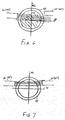
- the term "side of the tube” as used herein means those portions of the tube defined by a plane 42 which intersects the longitudinal axis of the tube and is generally normal thereto, as shown in Figs. 6 and 7.
- Illumination fiber optic bundle 30 and illumination fiber optic bundle 55 must each be positioned with respect to the respective side of the tube 40 so that the direction in which each directs light through the tube 40 will result in substantially no cross-talk therebetween. In a preferred embodiment of the present invention, this result is optimally achieved by positioning bundle 30 and bundle 55 with respect to the side of the tube 40 and with respect to one another such that the direction of the light from bundle 30 as it passes through the tube 40 is substantially opposite to the direction of the light from bundle 55 as it passes through the tube.
- bundles 45 and 60 are positioned with respect to tube 40 such that each only receives light which passes outside of a predetermined region as defined below.
- a predetermined region as defined below.
- the predetermined region described above is defined as that area in which substantially all of the light rays pass when the tube contains a liquid.
- the dimensional placement of bundles 30 and 55 and bundles 45 and 60 with respect to plane 43 which intersects the longitudinal axis of the tube 40 is critical.
- the placement must be such that the light rays when passing through a liquid filled tube 40 are refracted into the predetermined region described above not occupied by either the bundle 45 or the bundle 60, whichever the case may be, and must also be such that the light rays when passing through a gas filled tube 40 are not so refracted and instead pass outside of the predetermined region and into an area occupied by either the bundle 45 or the bundle 60, whichever the case may be.
- a film of isolating liquid such as oil
- bundles 30 and 55 and bundles 45 and 60 be placed in the upper half of tube 40, meaning above the plane 43 as shown in Figs. 6 and 7, so that the light path is through the upper half of the tube 40.
- This placement is preferred because the isolating liquid tends to pool in the lower half of the tube 40 at low stream velocities, which would result in decreased performance if bundles 30 and 55 and bundles 45 and 60 were placed in the lower half of tube 40 because the light path would be through the lower half of the tube 40 and thus through the pooled isolating liquid.
- no isolating liquid is used, then placement of the bundles 30 and 55 and bundles 45 and 60 in the upper half of the tube 40 as compared to the lower half of the tube 40 is not so important.
- the light collected by bundles 45 and 60 is input into photodetector/amplifier integrated circuit devices 65 and 70, respectively, in order to convert the light into electrical energy.
- Suitable photodetector/amplifier integrated circuit devices are, for example, part no: OPT101 manufactured by Burr-Brown. It should be readily apparent to one of ordinary skill in the art that instead of using an integrated circuit device to perform the function of photodetector/amplifier integrated circuit devices 65 and 70, discrete photodetector and amplifier elements can be used.
- the outputs of the photodetector/amplifier integrated circuit devices 65 and 70 are respectively received by comparators 75 and 80 which compare the output of each photodetector/amplifier 65 and 70 to a reference voltage 85 to generate control signals 90 and 95.
- the signal output by photodetector/amplifier integrated circuit devices 65 and 70, respectively is low, i.e., below the reference voltage 85, so that comparators 75 and 80, respectively, produce control signals 90 and 95, respectively, having a first level which indicates that there is liquid in the tube 40.
- the signal output by photodetector/amplifier integrated circuit devices 65 and 70, respectively, is high, i.e., greater than the reference voltage 85, so that comparators 75 and 80 produce control signals 90 and 95, respectively, having a second level which indicates that there is gas in the tube 40.
- bundle 30 and bundle 55 are separated along the longitudinal axis of tube 40 by a distance that is smaller than the width of the smallest liquid or gas segment flowing through the tube 40. This orientation allows for the detection of the interface between any gas segment and any liquid segment.
- the control signals 90 and 95 are each fed to logic circuit 100.
- Logic circuit 100 is preferably implemented using conventional logic embodied in software using an integrated circuit chip or a solid state machine such that it outputs signals indicating the presence of either a liquid or gas segment and the direction of flow of the stream of liquid and gas segments.
- the particular set of logic states used to implement logic circuit 100 is described fully in the '946 patent and will not be repeated herein. It should be noted, however, that logic circuit 100 could be implemented in numerous ways by one of ordinary skill in the art to achieve the desired functionality without departing from the spirit and scope of the invention.
- FIG. 8 a block diagram of a bubble detector/direction sensor according to a second, preferred embodiment of the present invention is shown.
- comparators 75 and 80, reference voltage 85, controls signals 90 and 95, and logic circuit 100 shown in Fig. 5 are replaced by computer 120.
- the outputs of photodetector/amplifier integrated circuit devices 65 and 70 are fed directly into computer 120.
- the functionality and logic provided by comparators 75 and 80, reference voltage 85, control signals 90 and 95, and logic circuit 100 is provided completely by software loaded into computer 120.
- the computer 120 is then able to output signals indicating the direction of flow of the stream and the presence of either liquid or gas in the tube 40.
- the details of how to implement this functionality in software would be readily apparent to one of ordinary skill in the art and thus will not be provided herein.
- the embodiment shown in Fig. 8 is preferred because it eliminates the need for additional hardware components.
- bundles 30 and 55 are disposed on opposite sides of the tube 40 so that light travels through the tube 40 from bundle 30 in a direction substantially opposite to light traveling through the tube 40 from bundle 55 ensures that the bubble detector/direction sensor of the present invention is effectively immune from optical cross-talk between the two light path channels. This, advantageously, overcomes the aforementioned deficiency of the prior art.
- liquid segments containing a marker dye having known absorbance characteristics can be detected and used as indicators of the location of particular segments in the stream.
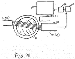
- FIG. 9A an alternative embodiment of the present invention is shown in which a liquid segment containing a marker dye also is able to be detected.
- collection fiber optic bundle 110 is positioned adjacent the tube 40 on a side of the tube 40 opposite either bundle 30 or bundle 55. Furthermore, bundle 110 is positioned within the predetermined region discussed with reference to Figs. 6 and 7 such that when the tube 40 contains liquid, the light from either bundle 30 or bundle 55 is bent or refracted when passing through the tube and is directed to bundle 110.
- the light collected by bundle 110 is output to photodetector 115 and then to amplifier 116 to convert the light to electrical energy.
- the discrete photodetector and amplifier components 115 and 116 can be replaced by a photodetector/amplifier integrated circuit device as described above.
- Logic circuit 100 is implemented using conventional logic such that, when the bubble detector/direction sensor determines that liquid is present in the tube 40 as described above, logic circuit 100 can determine whether the liquid is a sample segment or a segment containing marker dye using the light collected by bundle 110 and the known absorbance characteristics of the particular marker dye or dyes used. Specifically, when a liquid segment without marker dye is present in the tube, a particular amount of light will reach the bundle 110 due to the characteristics of the liquid samples. This amount of light will be substantially consistent among all of the liquid segments that are liquid samples to be analyzed.
- the logic circuit 100 is able to distinguish between liquid samples with and without marker dye based upon the amount of light received by the bundle 110. As a result, the location of particular segments in the stream can be determined and tracked.
- the particulars necessary to implement conventional logic in logic circuit 100 to achieve the desired functionality would be readily apparent to one of ordinary skill in the art and thus will not be discussed herein.
- FIG. 9B a further alternative embodiment of the present invention is shown in which a liquid segment containing a marker dye is also able to be detected and in which the logic circuit 100 shown in Fig. 9A is replaced with computer 120.
- Computer 120 is loaded with software which performs all of the functionality of logic circuit 100 described above. The details of how to implement this functionality in software would be readily apparent to one of ordinary skill in the art and thus will not be discussed herein.
Landscapes
- General Health & Medical Sciences (AREA)
- General Physics & Mathematics (AREA)
- Life Sciences & Earth Sciences (AREA)
- Chemical & Material Sciences (AREA)
- Analytical Chemistry (AREA)
- Biochemistry (AREA)
- Health & Medical Sciences (AREA)
- Immunology (AREA)
- Physics & Mathematics (AREA)
- Pathology (AREA)
- Investigating Or Analysing Materials By Optical Means (AREA)
- Automatic Analysis And Handling Materials Therefor (AREA)
- Measurement Of Levels Of Liquids Or Fluent Solid Materials (AREA)
- Indicating Or Recording The Presence, Absence, Or Direction Of Movement (AREA)
- Optical Measuring Cells (AREA)
Applications Claiming Priority (2)
| Application Number | Priority Date | Filing Date | Title |
|---|---|---|---|
| US995738 | 1997-12-22 | ||
| US08/995,738 US5960129A (en) | 1997-12-22 | 1997-12-22 | Method and apparatus for detecting liquid and gas segment flow through a tube |
Publications (2)
| Publication Number | Publication Date |
|---|---|
| EP0924509A2 true EP0924509A2 (fr) | 1999-06-23 |
| EP0924509A3 EP0924509A3 (fr) | 1999-12-01 |
Family
ID=25542160
Family Applications (1)
| Application Number | Title | Priority Date | Filing Date |
|---|---|---|---|
| EP98123778A Withdrawn EP0924509A3 (fr) | 1997-12-22 | 1998-12-15 | Procédé et dispositif pour détecter l'écoulement de segments liquides et gazeux à travers un tube |
Country Status (4)
| Country | Link |
|---|---|
| US (1) | US5960129A (fr) |
| EP (1) | EP0924509A3 (fr) |
| JP (1) | JPH11241995A (fr) |
| CA (1) | CA2254690A1 (fr) |
Cited By (2)
| Publication number | Priority date | Publication date | Assignee | Title |
|---|---|---|---|---|
| WO2001036861A1 (fr) * | 1999-11-16 | 2001-05-25 | Willy Vogel Aktiengesellschaft | Procede et dispositif pour surveiller le flux d'huile d'un dispositif servant a la lubrification par huile et air de composants |
| EP1712282A3 (fr) * | 2005-04-15 | 2010-01-27 | Hitachi Software Engineering Co., Ltd. | Puce d'essai et système de puce d'essai |
Families Citing this family (42)
| Publication number | Priority date | Publication date | Assignee | Title |
|---|---|---|---|---|
| US6623971B2 (en) * | 1999-01-11 | 2003-09-23 | Bayer Corporation | Method and apparatus for conducting a stat immunoassay analysis in a capsule chemistry analysis system |
| JP4688366B2 (ja) * | 2001-08-24 | 2011-05-25 | 東亜ディーケーケー株式会社 | 吸光度検出器 |
| CA2520862A1 (fr) * | 2003-03-31 | 2004-10-21 | Zolo Technologies, Inc. | Procede et appareil pour surveiller et reguler une combustion |
| DE112005000331B4 (de) * | 2004-03-05 | 2019-03-28 | Waters Technologies Corp. (N.D.Ges.D. Staates Delaware) | Optimierte Hochleistungs-Flüssigkeitschromatographieprobeneinbringung mit Blasendetektion |
| US7787728B2 (en) * | 2004-03-31 | 2010-08-31 | Zolo Technologies, Inc. | Optical mode noise averaging device |
| GB0417337D0 (en) * | 2004-08-04 | 2004-09-08 | Chu Andrew C | Low cost air bubble detector and alarm system for fluid administrative applications |
| US7403125B2 (en) * | 2005-05-06 | 2008-07-22 | Accuri Cytometers, Inc. | Flow cytometry system with bubble detection |
| US8017402B2 (en) | 2006-03-08 | 2011-09-13 | Accuri Cytometers, Inc. | Fluidic system for a flow cytometer |
| US8303894B2 (en) | 2005-10-13 | 2012-11-06 | Accuri Cytometers, Inc. | Detection and fluidic system of a flow cytometer |
| US8544279B2 (en) * | 2005-11-04 | 2013-10-01 | Zolo Technologies, Inc. | Method and apparatus for spectroscopic measurements in the combustion zone of a gas turbine engine |
| US8283177B2 (en) * | 2006-03-08 | 2012-10-09 | Accuri Cytometers, Inc. | Fluidic system with washing capabilities for a flow cytometer |
| US7780916B2 (en) * | 2006-03-08 | 2010-08-24 | Accuri Cytometers, Inc. | Flow cytometer system with unclogging feature |
| US7770434B2 (en) * | 2006-04-27 | 2010-08-10 | General Electric Company | System and method for in-process integrity test of a filter |
| US8715573B2 (en) | 2006-10-13 | 2014-05-06 | Accuri Cytometers, Inc. | Fluidic system for a flow cytometer with temporal processing |
| US8445286B2 (en) | 2006-11-07 | 2013-05-21 | Accuri Cytometers, Inc. | Flow cell for a flow cytometer system |
| US8432541B2 (en) * | 2007-12-17 | 2013-04-30 | Accuri Cytometers, Inc. | Optical system for a flow cytometer with an interrogation zone |
| AU2010203674B2 (en) | 2009-01-09 | 2014-09-25 | Onpoint Technologies, Llc | Method and apparatus for monitoring combustion properties in an interior of a boiler |
| US20110061471A1 (en) * | 2009-06-02 | 2011-03-17 | Rich Collin A | System and method of verification of a sample for a flow cytometer |
| US8507279B2 (en) * | 2009-06-02 | 2013-08-13 | Accuri Cytometers, Inc. | System and method of verification of a prepared sample for a flow cytometer |
| US8786857B2 (en) | 2009-08-10 | 2014-07-22 | Zolo Technologies, Inc. | Mitigation of optical signal noise using a multimode transmit fiber |
| US9551600B2 (en) | 2010-06-14 | 2017-01-24 | Accuri Cytometers, Inc. | System and method for creating a flow cytometer network |
| EP2633284B1 (fr) | 2010-10-25 | 2021-08-25 | Accuri Cytometers, Inc. | Systèmes et interface utilisateur pour collecter un ensemble de données dans un cytomètre de flux |
| JP5593291B2 (ja) * | 2011-09-21 | 2014-09-17 | 株式会社日立ハイテクノロジーズ | 自動分析装置 |
| US9366621B2 (en) | 2012-04-19 | 2016-06-14 | Zolo Technologies, Inc. | In-furnace retro-reflectors with steerable tunable diode laser absorption spectrometer |
| WO2014118944A1 (fr) * | 2013-01-31 | 2014-08-07 | テルモ株式会社 | Sonde de goutte-à-goutte intraveineux et pompe de perfusion dotée de la sonde de goutte-à-goutte |
| US10585075B2 (en) | 2014-02-27 | 2020-03-10 | Elemental Scientific, Inc. | System for collecting liquid samples |
| KR102445624B1 (ko) | 2014-02-27 | 2022-09-21 | 엘리멘탈 사이언티픽, 인코포레이티드 | 원거리에서 액체 샘플을 수집하기 위한 시스템 |
| WO2016105704A1 (fr) | 2014-12-23 | 2016-06-30 | Zolo Technologies, Inc. | Architecture tdlas pour longueurs d'onde largement espacées |
| CN107567652A (zh) * | 2015-03-12 | 2018-01-09 | 非视觉污染分析科学技术有限公司 | 基板污染物分析装置及基板污染物分析方法 |
| KR102608219B1 (ko) | 2015-06-26 | 2023-11-29 | 엘리멘탈 사이언티픽, 인코포레이티드 | 액체 샘플 수집을 위한 시스템 |
| US10901228B2 (en) * | 2017-06-27 | 2021-01-26 | The Boeing Company | Cavity with curved beam replicator and method of determining a characteristic of a medium therein |
| JP7110320B2 (ja) * | 2017-08-01 | 2022-08-01 | エフ.ホフマン-ラ ロシュ アーゲー | 液体試料中の検体の検出の動作をモニタする方法 |
| US10352866B1 (en) | 2018-04-09 | 2019-07-16 | Mehmet Arbatli | System and method of detecting within a liquid flow of a pipe |
| CN113015900B (zh) * | 2018-11-19 | 2024-04-26 | 京瓷株式会社 | 流体检测传感器以及流体检测装置 |
| CN110133320B (zh) * | 2019-05-23 | 2021-07-27 | 暨南大学 | 等离子体共振光纤热线风速计、检测系统及方法 |
| CN110346584B (zh) * | 2019-07-10 | 2024-01-02 | 深圳金迈隆电子技术有限公司 | 一种片上实验室光电检测装置及方法 |
| US12584933B2 (en) * | 2019-12-26 | 2026-03-24 | Hitachi High-Tech Corporation | Automatic analyzer and control program for automatic analyzer |
| CN111089842A (zh) * | 2019-12-31 | 2020-05-01 | 聚光科技(杭州)股份有限公司 | 水质检测系统 |
| US11982683B1 (en) | 2021-04-12 | 2024-05-14 | Mehmet Arbatli | System and method of detecting skimmer and pump basket clogging by sensing changes in local liquid pressure |
| US11768142B1 (en) | 2021-04-12 | 2023-09-26 | Mehmet Arbatli | Bubble detection system and method within a liquid flow of a pipe by sensing changes in local liquid pressure |
| LU103065B1 (en) | 2023-01-24 | 2024-07-24 | Stratec Se | Fluid analysis using optical systems |
| LU103097B1 (en) | 2023-03-31 | 2024-10-03 | Stratec Se | Optical fluid verification for air bubble detection in fluid filled hoses |
Family Cites Families (22)
| Publication number | Priority date | Publication date | Assignee | Title |
|---|---|---|---|---|
| US4130010A (en) * | 1977-08-15 | 1978-12-19 | Westinghouse Electric Corp. | Bubble detector |
| US4117727A (en) * | 1977-12-12 | 1978-10-03 | Friswell David R | Bubble sensor and method |
| US4235095A (en) * | 1978-09-01 | 1980-11-25 | Tif Instruments, Inc. | Device for detecting inhomogeneities such as gas bubbles |
| US4210809A (en) * | 1979-03-16 | 1980-07-01 | Technicon Instruments Corporation | Method and apparatus for the non-invasive determination of the characteristics of a segmented fluid stream |
| US4344429A (en) * | 1979-12-13 | 1982-08-17 | Baxter Travenol Laboratories, Inc. | Bubble detector with feedback circuit for improved sensitivity |
| US4312341A (en) * | 1979-12-13 | 1982-01-26 | Baxter Travenol Laboratories, Inc. | Bubble detector |
| US4366384A (en) * | 1980-06-18 | 1982-12-28 | Cutter Laboratories, Inc. | Air bubble detector |
| US4367736A (en) * | 1980-08-25 | 1983-01-11 | Baxter Travenol Laboratories, Inc. | System for detecting bubble formation in clear and opaque fluids |
| US4599888A (en) * | 1983-12-07 | 1986-07-15 | Teledyne Industries, Inc. | Air bubble detector device |
| US4607520A (en) * | 1984-01-09 | 1986-08-26 | Introtek Corporation | Method and apparatus for detecting discontinuities in a fluid stream |
| US4736590A (en) * | 1985-01-31 | 1988-04-12 | Monticelli Jr Frank R | Apparatus and method for continuously monitoring non-condensable gases in a flow of mixed gases |
| IL82492A0 (en) * | 1986-05-21 | 1987-11-30 | Hercules Inc | Apparatus and method for analysis of liquid samples |
| FR2599496B1 (fr) * | 1986-05-28 | 1992-02-14 | Mms | Detecteur de bulles dans un circuit de liquide |
| US4727277A (en) * | 1987-01-09 | 1988-02-23 | Tello Adams | Electronic bubble detector apparatus |
| US4884065A (en) * | 1988-06-13 | 1989-11-28 | Pacesetter Infusion, Ltd. | Monitor for detecting tube position and air bubbles in tube |
| US4920336A (en) * | 1988-11-22 | 1990-04-24 | Fisher Scientific Company | Method and apparatus for monitoring the level of the contents in a container |
| US5083862A (en) * | 1990-08-13 | 1992-01-28 | City Of Hope | Liquid bubble detector |
| US5043706A (en) * | 1990-10-19 | 1991-08-27 | Eastman Kodak Company | System and method for detecting bubbles in a flowing fluid |
| US5205153A (en) * | 1992-01-23 | 1993-04-27 | Cobe Laboratories, Inc. | Method and apparatus for detection of air bubbles in tubing |
| CA2125546A1 (fr) * | 1993-08-13 | 1995-02-14 | David Kleinschmitt | Methode et appareil pour detecter une interface entre liquides et gaz |
| US5455423A (en) * | 1993-08-25 | 1995-10-03 | Orbital Sciences Corporation | Gas bubble detector |
| US5539386A (en) * | 1994-03-07 | 1996-07-23 | J-Kem Electronics, Inc. | Sensor for detecting air/liquid transitions in a transparent tubing |
-
1997
- 1997-12-22 US US08/995,738 patent/US5960129A/en not_active Expired - Fee Related
-
1998
- 1998-11-19 CA CA002254690A patent/CA2254690A1/fr not_active Abandoned
- 1998-12-11 JP JP10352643A patent/JPH11241995A/ja active Pending
- 1998-12-15 EP EP98123778A patent/EP0924509A3/fr not_active Withdrawn
Cited By (3)
| Publication number | Priority date | Publication date | Assignee | Title |
|---|---|---|---|---|
| WO2001036861A1 (fr) * | 1999-11-16 | 2001-05-25 | Willy Vogel Aktiengesellschaft | Procede et dispositif pour surveiller le flux d'huile d'un dispositif servant a la lubrification par huile et air de composants |
| US6807977B1 (en) | 1999-11-16 | 2004-10-26 | Willy Vogel Aktiengesellschaft | Method and device for monitoring the flow of oil pertaining to a device for the oil and air lubrication of components |
| EP1712282A3 (fr) * | 2005-04-15 | 2010-01-27 | Hitachi Software Engineering Co., Ltd. | Puce d'essai et système de puce d'essai |
Also Published As
| Publication number | Publication date |
|---|---|
| US5960129A (en) | 1999-09-28 |
| CA2254690A1 (fr) | 1999-06-22 |
| EP0924509A3 (fr) | 1999-12-01 |
| JPH11241995A (ja) | 1999-09-07 |
Similar Documents
| Publication | Publication Date | Title |
|---|---|---|
| US5960129A (en) | Method and apparatus for detecting liquid and gas segment flow through a tube | |
| EP0638800B1 (fr) | Procédé et appareil pour distiguer un liquide d'un gaz | |
| US5864392A (en) | Method for optically detecting gas bubbles moving in a coolant | |
| US6409141B1 (en) | Particle analyzer and composite lens formed by integrally joining plural lens elements of different focal points | |
| US6106710A (en) | Fraction collection delay calibration for liquid chromatography | |
| US4980278A (en) | Method of effecting immunological analysis and apparatus for carrying out the same | |
| US10126229B2 (en) | Optical measurement device | |
| EP0743514A1 (fr) | Capteur à fibres optiques pour la mesure de la réflectance de lumière diffuse | |
| EP0841556A1 (fr) | Sonde et méthode de détermination d'indices d'un sérum dans des échantillons de sérum | |
| US6767467B2 (en) | Fraction collection delay calibration for liquid chromatography | |
| CA2842608A1 (fr) | Appareil servant a determiner une position verticale d'au moins une interface entre une premiere composante et au moins une deuxieme composante et systeme d'automatisation de laboratoire | |
| CN110226082B (zh) | 具有多个强度峰值设计的流式细胞仪 | |
| CN110514575B (zh) | 量子点编码微球的解码装置及方法 | |
| KR940002496B1 (ko) | 부유미입자 측정 방법 및 그 장치 | |
| CN112229780A (zh) | 一种改进的基于光纤集成微流芯片的流式细胞仪 | |
| JPS63298137A (ja) | イメ−ジファイバを用いた検体分析装置 | |
| EP0903571A2 (fr) | Dispositif et procédé de détermination de la concentration de substances particulières | |
| FI96451C (fi) | Refraktometri | |
| KR101970689B1 (ko) | 광섬유를 이용한 유세포 분석 시스템 | |
| US4501969A (en) | Photometric apparatus and process | |
| WO2020182742A1 (fr) | Appareil et procédés pour test de particules | |
| JPH11218437A (ja) | 微量液量判別装置 | |
| JPH0798239A (ja) | 透明容器内試料の分量測定方法およびその装置 | |
| JP2010226978A (ja) | セルソータ | |
| KR102122020B1 (ko) | 혈구 분석 장치, 이를 이용한 혈구 분석 방법 |
Legal Events
| Date | Code | Title | Description |
|---|---|---|---|
| PUAI | Public reference made under article 153(3) epc to a published international application that has entered the european phase |
Free format text: ORIGINAL CODE: 0009012 |
|
| AK | Designated contracting states |
Kind code of ref document: A2 Designated state(s): AT BE CH CY DE DK ES FI FR GB GR IE IT LI LU MC NL PT SE |
|
| AX | Request for extension of the european patent |
Free format text: AL;LT;LV;MK;RO;SI |
|
| RIC1 | Information provided on ipc code assigned before grant |
Free format text: 6G 01N 21/85 A, 6G 01N 35/08 B |
|
| PUAL | Search report despatched |
Free format text: ORIGINAL CODE: 0009013 |
|
| AK | Designated contracting states |
Kind code of ref document: A3 Designated state(s): AT BE CH CY DE DK ES FI FR GB GR IE IT LI LU MC NL PT SE |
|
| AX | Request for extension of the european patent |
Free format text: AL;LT;LV;MK;RO;SI |
|
| 17P | Request for examination filed |
Effective date: 20000602 |
|
| AKX | Designation fees paid |
Free format text: AT BE CH CY DE DK ES FI FR GB GR IE IT LI LU MC NL PT SE |
|
| STAA | Information on the status of an ep patent application or granted ep patent |
Free format text: STATUS: THE APPLICATION IS DEEMED TO BE WITHDRAWN |
|
| 18D | Application deemed to be withdrawn |
Effective date: 20060928 |