EP2633284B1 - Systèmes et interface utilisateur pour collecter un ensemble de données dans un cytomètre de flux - Google Patents
Systèmes et interface utilisateur pour collecter un ensemble de données dans un cytomètre de flux Download PDFInfo
- Publication number
- EP2633284B1 EP2633284B1 EP11838544.2A EP11838544A EP2633284B1 EP 2633284 B1 EP2633284 B1 EP 2633284B1 EP 11838544 A EP11838544 A EP 11838544A EP 2633284 B1 EP2633284 B1 EP 2633284B1
- Authority
- EP
- European Patent Office
- Prior art keywords
- detector
- light
- detectors
- virtual
- array
- Prior art date
- Legal status (The legal status is an assumption and is not a legal conclusion. Google has not performed a legal analysis and makes no representation as to the accuracy of the status listed.)
- Active
Links
Images


Classifications
-
- G—PHYSICS
- G01—MEASURING; TESTING
- G01N—INVESTIGATING OR ANALYSING MATERIALS BY DETERMINING THEIR CHEMICAL OR PHYSICAL PROPERTIES
- G01N15/00—Investigating characteristics of particles; Investigating permeability, pore-volume or surface-area of porous materials
- G01N15/10—Investigating individual particles
- G01N15/14—Optical investigation techniques, e.g. flow cytometry
- G01N15/1434—Optical arrangements
-
- G—PHYSICS
- G01—MEASURING; TESTING
- G01J—MEASUREMENT OF INTENSITY, VELOCITY, SPECTRAL CONTENT, POLARISATION, PHASE OR PULSE CHARACTERISTICS OF INFRARED, VISIBLE OR ULTRAVIOLET LIGHT; COLORIMETRY; RADIATION PYROMETRY
- G01J3/00—Spectrometry; Spectrophotometry; Monochromators; Measuring colours
- G01J3/02—Details
- G01J3/0205—Optical elements not provided otherwise, e.g. optical manifolds, diffusers, windows
- G01J3/0208—Optical elements not provided otherwise, e.g. optical manifolds, diffusers, windows using focussing or collimating elements, e.g. lenses or mirrors; performing aberration correction
-
- G—PHYSICS
- G01—MEASURING; TESTING
- G01J—MEASUREMENT OF INTENSITY, VELOCITY, SPECTRAL CONTENT, POLARISATION, PHASE OR PULSE CHARACTERISTICS OF INFRARED, VISIBLE OR ULTRAVIOLET LIGHT; COLORIMETRY; RADIATION PYROMETRY
- G01J3/00—Spectrometry; Spectrophotometry; Monochromators; Measuring colours
- G01J3/02—Details
- G01J3/0205—Optical elements not provided otherwise, e.g. optical manifolds, diffusers, windows
- G01J3/0229—Optical elements not provided otherwise, e.g. optical manifolds, diffusers, windows using masks, aperture plates, spatial light modulators or spatial filters, e.g. reflective filters
-
- G—PHYSICS
- G01—MEASURING; TESTING
- G01J—MEASUREMENT OF INTENSITY, VELOCITY, SPECTRAL CONTENT, POLARISATION, PHASE OR PULSE CHARACTERISTICS OF INFRARED, VISIBLE OR ULTRAVIOLET LIGHT; COLORIMETRY; RADIATION PYROMETRY
- G01J3/00—Spectrometry; Spectrophotometry; Monochromators; Measuring colours
- G01J3/12—Generating the spectrum; Monochromators
- G01J3/18—Generating the spectrum; Monochromators using diffraction elements, e.g. grating
-
- G—PHYSICS
- G01—MEASURING; TESTING
- G01J—MEASUREMENT OF INTENSITY, VELOCITY, SPECTRAL CONTENT, POLARISATION, PHASE OR PULSE CHARACTERISTICS OF INFRARED, VISIBLE OR ULTRAVIOLET LIGHT; COLORIMETRY; RADIATION PYROMETRY
- G01J3/00—Spectrometry; Spectrophotometry; Monochromators; Measuring colours
- G01J3/28—Investigating the spectrum
- G01J3/2803—Investigating the spectrum using photoelectric array detector
-
- G—PHYSICS
- G01—MEASURING; TESTING
- G01J—MEASUREMENT OF INTENSITY, VELOCITY, SPECTRAL CONTENT, POLARISATION, PHASE OR PULSE CHARACTERISTICS OF INFRARED, VISIBLE OR ULTRAVIOLET LIGHT; COLORIMETRY; RADIATION PYROMETRY
- G01J3/00—Spectrometry; Spectrophotometry; Monochromators; Measuring colours
- G01J3/28—Investigating the spectrum
- G01J3/30—Measuring the intensity of spectral lines directly on the spectrum itself
- G01J3/36—Investigating two or more bands of a spectrum by separate detectors
-
- G—PHYSICS
- G01—MEASURING; TESTING
- G01N—INVESTIGATING OR ANALYSING MATERIALS BY DETERMINING THEIR CHEMICAL OR PHYSICAL PROPERTIES
- G01N15/00—Investigating characteristics of particles; Investigating permeability, pore-volume or surface-area of porous materials
- G01N15/10—Investigating individual particles
- G01N15/14—Optical investigation techniques, e.g. flow cytometry
-
- G—PHYSICS
- G01—MEASURING; TESTING
- G01N—INVESTIGATING OR ANALYSING MATERIALS BY DETERMINING THEIR CHEMICAL OR PHYSICAL PROPERTIES
- G01N15/00—Investigating characteristics of particles; Investigating permeability, pore-volume or surface-area of porous materials
- G01N15/10—Investigating individual particles
- G01N15/14—Optical investigation techniques, e.g. flow cytometry
- G01N15/1404—Handling flow, e.g. hydrodynamic focusing
-
- G—PHYSICS
- G01—MEASURING; TESTING
- G01N—INVESTIGATING OR ANALYSING MATERIALS BY DETERMINING THEIR CHEMICAL OR PHYSICAL PROPERTIES
- G01N15/00—Investigating characteristics of particles; Investigating permeability, pore-volume or surface-area of porous materials
- G01N15/10—Investigating individual particles
- G01N15/14—Optical investigation techniques, e.g. flow cytometry
- G01N15/1429—Signal processing
-
- G—PHYSICS
- G16—INFORMATION AND COMMUNICATION TECHNOLOGY [ICT] SPECIALLY ADAPTED FOR SPECIFIC APPLICATION FIELDS
- G16B—BIOINFORMATICS, i.e. INFORMATION AND COMMUNICATION TECHNOLOGY [ICT] SPECIALLY ADAPTED FOR GENETIC OR PROTEIN-RELATED DATA PROCESSING IN COMPUTATIONAL MOLECULAR BIOLOGY
- G16B45/00—ICT specially adapted for bioinformatics-related data visualisation, e.g. displaying of maps or networks
-
- G—PHYSICS
- G16—INFORMATION AND COMMUNICATION TECHNOLOGY [ICT] SPECIALLY ADAPTED FOR SPECIFIC APPLICATION FIELDS
- G16B—BIOINFORMATICS, i.e. INFORMATION AND COMMUNICATION TECHNOLOGY [ICT] SPECIALLY ADAPTED FOR GENETIC OR PROTEIN-RELATED DATA PROCESSING IN COMPUTATIONAL MOLECULAR BIOLOGY
- G16B5/00—ICT specially adapted for modelling or simulations in systems biology, e.g. gene-regulatory networks, protein interaction networks or metabolic networks
-
- G—PHYSICS
- G16—INFORMATION AND COMMUNICATION TECHNOLOGY [ICT] SPECIALLY ADAPTED FOR SPECIFIC APPLICATION FIELDS
- G16B—BIOINFORMATICS, i.e. INFORMATION AND COMMUNICATION TECHNOLOGY [ICT] SPECIALLY ADAPTED FOR GENETIC OR PROTEIN-RELATED DATA PROCESSING IN COMPUTATIONAL MOLECULAR BIOLOGY
- G16B99/00—Subject matter not provided for in other groups of this subclass
-
- G—PHYSICS
- G06—COMPUTING OR CALCULATING; COUNTING
- G06M—COUNTING MECHANISMS; COUNTING OF OBJECTS NOT OTHERWISE PROVIDED FOR
- G06M11/00—Counting of objects distributed at random, e.g. on a surface
- G06M11/02—Counting of objects distributed at random, e.g. on a surface using an electron beam scanning a surface line by line, e.g. of blood cells on a substrate
Definitions
- This invention relates generally to the flow cytometer field, and more specifically to a new and useful systems and user interface in the flow cytometry field.
- a flow cytometer In a flow cytometer, light is directed onto a stream of sample fluid such that the light impinges and typically excites particles in the sample, causing the excited particles to emit light.
- the detection of the emitted light provides data that can be analyzed for characterizing the particles and the sample fluid, such as count, physical structure, chemical structure, and other useful information in applications such as for research and clinical purposes.
- the detection system is therefore a crucial component of a flow cytometer and is a factor in not only the quality (e.g., sensitivity, bandwidth) of the collected data, but also the overall structure and cost of the complete flow cytometer system.
- the detection system includes photomultiplier tubes, or PMTs, which have relatively high sensitivity and high bandwidth, and produces data with relatively low noise.
- PMTs have several disadvantages, such as being relatively expensive and exhibiting temperature drift.
- a typical flow cytometer detector has a limited collection range.
- the collection range of a typical flow cytometer is smaller than the signal range of the objects being analyzed with the flow cytometer.
- the typical detector is supplied with a gain level and/or amplifier.
- Detectors typically collect data relative to an object's size (light scatter) or brightness (fluorescence); both types of data are often collected on each object detected in the sample.
- the gain level is increased. With an increased gain level, however, the signals from large or bright objects are too intense to be collected.
- the gain level is decreased. With a decreased gain level, however, the signals from small or faint objects are too weak to be collected.
- detectors in flow cytometers are also complicated by complex optical systems.
- beam splitters and filters must be arranged in a very particular order to properly direct light of particular wavelengths to the appropriate detectors. Rearrangement of the optical system is required whenever a different wavelength detection configuration is required, such as experiments or tests using different fluorochromes. A user must skillfully perform this rearrangement, or the detector system will not function correctly.
- This limitation prevents the easy swapability of the filters and the easy modification of detection parameters.
- the particular arrangement of the optical system decreases the reliability and the ruggedness of the flow cytometers, since alignment of the various optical components affects the operability of the detection system. Examples of prior art systems include US2008/215297 , US2007/188737 , US2008/263468 , JP2008197043 and WO2005/098379 .
- This invention provides such new and useful systems and user interface for collecting a data set in a flow cytometer.
- the invention provides a system according to claim 1 and a method according to claim 4.
- systems for collecting a data set in a flow cytometer include optical and detection systems in a flow cytometer 102 having a flow channel with an interrogation zone and an illumination source that impinges the interrogation zone from a particular direction.
- the optical system 100 includes a lens subsystem including a collimating element that receives and collimates light from the interrogation zone, a light dispersion element that disperses the collimated light into a continuous wavelength spectrum of light, and a focusing lens that focuses light spectrum onto an array of adjacent detection points.
- the detection system 200 for a flow cytometer includes at least one semiconductor detector device that detects the focused light at a detection point and produces a signal corresponding to the detected light; a low noise amplifier circuit that amplifies the signal and is characterized by a high gain-bandwidth product; and a noise filter that reduces electronic noise from the amplified signal.
- the detection system 200 includes multiple such detectors in a detector array that collectively detects a full spectral range of input signals from the flow cytometer, in which each detector detects a subset spectral range of the full spectral range.
- the user interface 300 enables a user to create a set of virtual detector channels by grouping detectors in the detector array, such that each virtual detector channel corresponds to a detector group and has a virtual detector channel range including the sum of subset spectral ranges of the detectors in the corresponding detector group.
- the systems and user interface described herein eliminate the discrete and complex system of detectors and filters used in conventional flow cytometers, thereby simplifying the overall flow cytometer system and enabling a more compact, easier to use flow cytometer.
- the optical and detection systems also capture all usable light, thereby increasing the power and usability of the flow cytometer.
- the optical and detection systems and user interface are preferably integrated in a flow cytometer, the systems and user interface may alternatively be used in microscopy and/or any suitable apparatus or application for collecting and detecting light.
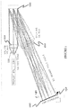
- the optical system 100 includes a lens subsystem including a collimating element 110 that receives and collimates light from the interrogation zone, a light dispersion element 120 that disperses the collimated light into a continuous wavelength spectrum of light, and a focusing lens 130 that focuses light spectrum onto an array of adjacent detection points 132, such that a detector array may collect the focused light at the adjacent detection points 132.
- the optical system 100 may further include a clean-up element that reduces spurious reflections and/or other undesired optical artifacts.
- the optical system 100 receives and directs light towards a detection system that includes photodiode light detectors, but may alternatively receive and direct light toward a detection system that includes phototransistor light detectors, or any suitable detector.
- the lens subsystem includes multiple lens and/or lens surfaces that function to manipulate the light from the illumination source into a form and/or to detection point locations where the light is detectable by a detector array.
- the collimating element 110 is a collimating lens that aligns light from the interrogation zone, and preferably an achromatic doublet lens, but may include any suitable combination of lenses or other collimating element.
- the collimating element 110 preferably perfectly or near-perfectly collimates the light into substantially parallel light rays, since the effects of imperfect collimation appear at subsequent stages of the lens subsystem, resulting in poorly-focused light at the detection points 132 and thereby degrading the detection of the light originating from the interrogation zone.
- the collimating element 110 may be coupled to or otherwise optically paired with an aplanatic meniscus lens 112.
- the pairing of the collimating element 110 and aplanatic meniscus lens 112 increases the effective numerical aperture of the first stage of the lens subsystem, thereby increasing the overall efficiency of light collection from the interrogation zone.
- the pairing also reduces the overall focal length of the first stage of the lens subsystem, without introducing additional undesirable spherical aberrations or other optical aberrations, which enables the lens subsystem to be made more compact.
- the collimating element 110 is an achromatic doublet lens with an effective focal length of approximately 30 millimeters and the aplanatic meniscus lens has an approximately 50 degree cone, such that the triplet lens combination of the collimating element and meniscus lens has an effective focal length of approximately 20 millimeters.
- the light dispersion element 120 functions to disperse the collimated light from the collimating element 110 into a continuous wavelength spectrum of light.
- the light dispersion element 120 is mounted in alignment with the output of the collimating element, such as in a frame, and may be permanently fixed or adjustable in position relative to the collimating element. As shown in FIGURE 1 , after passing through the light dispersion element 120, the light is preferably redirected such that light rays of the same wavelength are parallel and light rays of different wavelengths are nonparallel at relative angles corresponding to their relative position in the wavelength spectrum.
- the light dispersion element 120 is preferably one of multiple variations.
- the light dispersion element 120 includes a diffraction grating that splits and diffracts light into a continuous spectrum of light rays towards the third stage of the lens subsystem.
- the light dispersion element 120 includes a dispersive prism that breaks up the collimated light into a continuous spectrum of light rays towards the third stage of the lens subsystem.
- the dispersed light may follow a fold angle that is an acute angle, which may enable a more compact lens subsystem, or any suitable angle.
- the light dispersion element 120 is a diffraction grating or prism with a grating of approximately 600 lines/millimeter, and the light dispersion element provides a fold angle of approximately 22 degrees.
- the light dispersion element may include any suitable structure with any suitable level of grating and/or fold angle.
- the focusing lens 130 functions to focus the dispersed, continuous spectrum of light onto an array of adjacent detection points 132.
- the focusing lens 130 gathers light of similar wavelength together such that all light focused on the array of detection points 132 is arranged in spectral order, but the dispersed light may be focused in any suitable manner.
- beam splitters or additional stages in the lens subsystem may redirect selected spectral portions of the dispersed light to be arranged in any suitable spectral order, and/or focus selected spectral portions of the dispersed light onto detection points in any suitable location.
- Each detection point 132 may have a spot size of approximately 0.8 mm 2 , or any suitable spot size.
- the array of detection points 132 is preferably a linear array. For instance, light corresponding to shorter wavelengths is preferably focused near a first end of the array of detection points 132, and light corresponding to longer wavelengths is preferably focused near a second end of the array of detection points 132, opposite the first end.
- the array of detection points may alternatively be an arcuate array (e.g., an open arc segment or enclosed circle or ellipse) or any suitable shape.
- the focusing lens 130 has an effective focal length of approximately 160 millimeters and focuses the light to a linear array of detection points covering a dispersion distance of approximately 43 millimeters long.
- the focusing lens may be any suitable lens or lens surface, and may focus the light to any suitable arrangement of detection points.
- the optical system 100 may further include a clean-up element 140 that functions to reduce undesired optical artifacts or other aspects of the received light, such as crosstalk from spurious grating reflections.
- the clean-up element 140 includes an optical filter.
- the optical filter may be continuously variable, segmented, upper half, lower half, or any suitable type of filter.
- the filter may additionally and/or alternatively block one or more specific wavelengths from reaching the array of detector points 132, such as the wavelength of a laser or lasers used to excite fluorescent particles in the interrogation zone.
- such a blocking filter may include an optical notch filter, or a thin blocking bar that positioned at a particular detection point to absorb a particular wavelength or mask the detector from receiving light of the particular wavelength at the detection point, but the blocking filter may additionally and/or alternatively include any suitable filtering device.
- the clean-up element 140 includes a slit grid, which may include any suitable slit grid known to one ordinarily skilled in the art or other suitable slit grid.
- the optical system may include any suitable number of clean-up elements 140.
- One or more clean-up elements 140 may be positioned after the light dispersion stage of the lens subsystem and before or after the focusing stage of the lens subsystem, or in any suitable portion of the lens subsystem.
- the detection system 200 preferably includes one or more semiconductor light detector devices 212 in a detector array 210. Each semiconductor detector device 212 detects the light at a respective detection point 132 (focused by the optical system 100 described above, or any suitable optical system) and produces an electrical signal corresponding to the detected light. As shown in FIGURE 2 , the detection system 200 preferably further includes signal processing circuitry including: a low noise amplifier circuit 220 that boosts or amplifies the signal from the detector device 212 and that is characterized by a high gain-bandwidth product; and a noise filter 230 that reduces electronic noise from the amplified signal.
- a low noise amplifier circuit 220 that boosts or amplifies the signal from the detector device 212 and that is characterized by a high gain-bandwidth product
- a noise filter 230 that reduces electronic noise from the amplified signal.
- the semiconductor detector device 212 functions to convert light into an electrical signal having characteristics that correlate with the nature of the light received from the interrogation zone.
- the wavelength sensitivity of the detector device 212 is preferably optimized to detect light between a full range of approximately 400 nanometers and 900 nanometers in wavelength, either a subset of the full range or over the entire full range.
- the wavelength sensitivity of the detector device 212 may be optimized to minimize detection of light in the infrared range, such as to avoid responding to sources of heat in the flow cytometer or other instrument in which the detection system is integrated.
- the detector devices may be optimized to detect any suitable range of wavelengths of light.
- the angular sensitivity of the semiconductor detector device 212 may be optimized to receive light in a cone approximately corresponding to the focused cone of light emanating from the light focusing element of the optical system described above, while rejecting stray light passing outside of the cone, which may thereby minimize sensitivity to light traveling off-axis within the optical system. Furthermore, the semiconductor detector device 212 may be shielded from any backlight or other ambient light sources to minimize background noise in the signal and improve the accuracy of the resulting collected data set from the flow cytometer (or other instrument). The semiconductor device 212 may additionally and/or alternatively be shielded from electromagnetic fields to minimize induced electronic noise. Furthermore, the semiconductor detector device 212 may include temperature compensation to minimize any temperature-induced changes in gain or linearity of the output signal.
- the semiconductor detector device 212 may be any suitable semiconductor device or light detector device.
- the semiconductor detector device 212 is a photodiode, and more preferably a PIN photodiode, although the photodiode may be any suitable kind of diode.
- the photodiode preferably has a very low capacitance, such as approximately 20 pF or less. Since photodiodes with low capacitance are generally physically smaller and have a smaller light-sensitive region, the photodiode detector devices 212 are preferably placed at detection points 132 at which light is well-focused, such as by the optical system described above or any suitable optical system.
- the photodiode is preferably configured to output current that correlates with characteristics of the received light, but may alternatively be configured to output another suitable electrical characteristic, such as voltage.
- the semiconductor detector device 212 is a phototransistor.
- the phototransistor preferably has a very low capacitance and may have a small light-sensitive region such that the phototransistor requires placement at a detection point receiving well-focused light.
- the phototransistor may be configured to provide an output signal having a substantially linear gain response across the intended light power range of the input signals, such as by applying a suitable current bias to the base of the phototransistor, typically in the range of approximately 10 ⁇ m to 1mA.
- the output signal from the phototransistor may be converted from a current signal to a voltage signal, such as by feeding the output signal into the low-noise amplifier circuit, a load resistor or other suitable circuitry components.
- the phototransistor may provide additional current gain that may be leveraged to increase gain of the signal and/or increase the signal-to-noise ratio.
- the use of a phototransistor may reduce the required resistance value of the gain resistor in the amplifier circuit, and consequently may reduce the thermal noise contribution to overall detector noise.
- the low-noise amplifier circuit 220 functions to convert current input from the semiconductor detector device 212 to a voltage output and to amplify the signal from the semiconductor detector device 212.
- the low-noise amplifier circuit 220 preferably includes a transimpedance amplifier, but may be any suitable kind of amplifier.
- the amplifier circuit preferably has a high open-loop gain-bandwidth product, such as approximately 1 GHz or more.
- the combination of a semiconductor detector device 212 having low capacitance and a transimpedance amplifier having a high gain-bandwidth product may enable the detection system 200 to have high gain (to amplify the signal from the detector) while maintaining high sensitivity and high bandwidth.
- the amplifier circuit 220 may further be characterized with a high feedback resistance, low voltage noise and low current noise to reduce overall noise in the signal, and low input capacitance.
- the transimpedance amplifier has a feedback resistance between 1-20 MOhms and preferably more than approximately 10 MOhms, voltage noise of less than approximately 5 nV/rtHz, current noise of less than approximately 5fA/rtHz, and input capacitance less than approximately 6pF.
- the amplifier circuit 220 may additionally and/or alternatively include any suitable electronic components that perform current-to-voltage conversion, or the detection system may include any suitable conversion circuitry (e.g., a passive current-to-voltage converter).
- the amplifier circuit may additionally and/or alternatively include digital signal processing.
- the noise filter 230 functions to reduce electronic noise and/or photon-induced noise from the amplified signal, thereby increasing the signal-to-noise ratio.
- the noise filter 230 may include a low pass filter that quickly attenuates higher frequency noise above a predetermined cutoff point.
- the noise filter 230 may be implemented in hardware circuitry and/or digitally.
- the low pass filter includes 120 dB or better attenuation, preferably with a 500 kHz or smaller transition band.
- the noise filter may additionally and/or alternatively include further signal processing techniques such as a smoothing algorithm.
- the detection system 200 preferably includes multiple semiconductor light detector devices 212 in a detector array 210 that collectively detects a full spectral range 250 of input signals from the flow cytometer, and in which each detector detects a subset spectral range 252 of the full spectral range.
- the semiconductor detector device 212 e.g. photodiode or photo transistor
- the detection system detects a full spectral range 250 of input signals of approximately 400-900 nm, but may alternatively detect any suitable spectral range of light.
- the detection system 200 preferably is configured to have a bandwidth of at least approximately 400 kHz.
- the detection system 200 may have a bandwidth of at least approximately 2 MHz. Alternatively, the detection system 200 may have any suitable bandwidth. Furthermore, the detector array 210 preferably detects a wide range of input signals that includes at least a 1:100,000 ratio, and more preferably at least a 1:1,000,000 ratio, between the faintest objects and the brightest objects. In a preferred embodiment, the detector array 210 is a linear array, such that a dispersed spectrum of light may be incident on the detector array, with light of shorter wavelengths detected near a first end of the linear array and light of longer wavelengths detected near a second end of the linear array opposite the first end. Alternatively, the detector array 210 may be an arcuate array (e.g., an open arc segment or enclosed circle or ellipse) or any suitable shape, preferably with adjacent and contiguous detector devices 212.
- an arcuate array e.g., an open arc segment or enclosed circle or ellipse
- Each detector device 212 in the detector array 210 preferably detects a respective portion or subset of the full spectral range 250 of the detection system 200.
- the detector array 210 is preferably capable of detecting a continuous spectral range of light, and each detector device 212 may be configured to detect a subset spectral range based on its individual characteristics, and/or by its relative position in the detector array 210.
- the detector array 210 may include 50 detectors that each detects light of approximately 10 nm wavelength increments, from approximately 400-900 nm.
- the subset spectral ranges 252 of the detectors 212 may be of equal span (e.g.
- each detector detects, as a result of capability and/or respective position in the detector array, a subset range of 10 nm in the full spectral range), or may be of unequal span.
- some or all of the detectors may detect light of overlapping spectra. For example, one detector may detect light of 510-530 nm, and an adjacent detector may detect light of 520-540 nm, such that the two adjacent detectors both detect light of 10 nm (520-530 nm).
- the detector array 210 may include any suitable number of detectors, and the detectors may detect any suitable wavelength ranges of light and/or overlapping wavelength ranges of light.
- the "spillover" spectral overlap resulting from detection of a particular wavelength of light by multiple detectors may be automatically compensated by techniques known and used by one ordinarily skilled in the art, compensated by user-controlled techniques, and/or any suitable compensation methods.
- the detector array 210 preferably detects a continuous spectral range of light, the detector array may alternatively detect a discontinuous spectral range of light, or selected subsets of the full spectral range 250 of light.
- individual detectors may be grouped into virtual detector channels 240, and/or actual detector channels, through which the data set from the flow cytometer or other instrument may be collected.
- Each virtual detector channel 240 corresponds to a detector group and has a virtual detector channel range 242 that includes the sum of the subset spectral ranges 252 of the detectors in the corresponding detector group.
- each virtual detector channel 240 includes the summed or combined input signals collectively detected by the individual detectors 212 in the detector group corresponding to the virtual detector channel 240.
- Some or all of the virtual detector channels may include substantially equal virtual detector channel ranges or unequal virtual detector channel ranges.
- the detectors may be grouped in a first configuration corresponding to a first set of virtual detector channels 240 and in a second configuration corresponding to a second set of virtual detector channels 240, where the first and second configurations are different.
- the grouping of signals from the detectors may be arranged and repeatedly rearranged in different groups between uses and applications, without requiring physical rearrangement of the components of the optical system and detection system.
- the user interface 300 for a flow cytometer is used to enable the grouping of detector signals to form virtual detector channels through which data is collected and organized.
- the user interface 300 provides a method for collecting a data set for a flow cytometer sample in a flow cytometer including the steps of: providing a detector array S310 having a plurality of detectors that collectively detect a full spectral range of input signals from the flow cytometer, in which each detector detects a subset spectral range of the full spectral range; creating a set of virtual detector channels S320 by grouping detectors in the detector array, and collecting the full spectral range of input signals S370 from the flow cytometer sample with the detector array.
- Each virtual detector channel corresponds to a detector group and has a virtual detector channel range that includes the sum of subset spectral ranges of the detectors in the corresponding detector group.
- the step of creating a set of virtual detector channels S320 may be performed before and/or after the step of collecting input signals S370.
- the method may further include storing an initial data set based on the collected input signals S380 and/or storing a configuration file of the configuration of the virtual detector channels S390.
- the user interface 300 enables extraction of data from a flow cytometer system having the optical and/or detection systems as described above, or any suitable instrument having an array of multiple detectors that each detects a portion of a full spectrum of light input signals.
- the user interface 300 enables a more comprehensive collection of data, and simplifies the process for setting up and configuring the detector system of the flow cytometer.
- the user interface and method for collecting a data set may alternatively be used in any suitable system requiring detection of a substantial spectrum of signals, such as microscopy.
- the step of providing a detector array S310 includes providing a system that detects known subsets of an entire light (e.g., fluorescence) spectrum detected by the flow cytometer.
- the detector array is similar to the detection system described above and shown in FIGURES 2 and 3 , but may alternatively be any suitable detection system.
- the detector array includes separate individual detector devices that detect a dispersed full spectrum of light such that adjacent detectors may detect portions or subset spectral ranges of the full spectrum of light, and more preferably such that adjacent detectors detect contiguous subset spectral ranges of the full spectrum of light.
- each detector may detector light in 10 nm increments, such that a first detector may detect light having a wavelength of approximately 491-500 nm, a second middle detector may detect light having a wavelength of approximately 501-510 nm, and a third detector may detect light having a wavelength of approximately 511-521 nm.
- the detector array may include photodiodes, phototransistors, or any suitable kind of light detector.
- the step of creating a set of virtual detector channels S320 functions to organize the signals collected by detectors in the detector array into designated data channels.
- creating a set of virtual detector channels S320 includes grouping detectors in the detector array S322.
- Each virtual detector channel 240 corresponds to a detector group and has a virtual detector channel range that includes the sum of the subset spectral ranges of the detectors in the corresponding detector group.
- each virtual detector channel 240 includes the summed or combined input signals collectively detected by the individual detectors in the detector group corresponding to the virtual detector channel.
- One or more detector groups may include detectors that are physically contiguous with each other (e.g., a "block” of detectors and/or detect contiguous subset spectral ranges of light, such that the corresponding virtual detector channel range collects light of a continuous spectral range (as in virtual detector channels 240a, 240b, and 240d). Furthermore, one or more detector groups may include detectors that are not physical contiguous with each (e.g., a "split block” of detectors) and/or detect not contiguous subset spectral ranges of light, such that the corresponding virtual detector channel range collects light of a discontinuous spectral range, as in virtual detector channel 240c.
- the step of collecting the full spectral range of input signals S370 functions to gather raw data with the detector array.
- Collecting input signals S370 may include collecting a full dynamic range of input signals that provides at least a 1:100,000 ratio, and more preferably at least a 1:1,000,000 ratio, between the faintest signals and the brightest signals from the flow cytometer sample.
- the data is collected in a raw, unmodified format without adjustment in gain level of the detectors, but may be collected in any suitable manner.
- the step of creating a set of virtual detector channels S320 may be performed before and/or after the step of collecting input signals S370, such as before and/or after performing a sample run on the flow cytometer.
- the step of creating a set of virtual detector channels S320 is performed before collecting input signals.
- the step of creating a set of virtual detector channels S320 includes receiving a user selection of detector groups S330 in which the user manually enters or indicates detector groups that make up the detector channels. For example, each detector may be labeled or numbered, and the user may specify that detectors "x" through "y" is a detector group.
- each detector is designated for detecting a particular subset spectrum range of input signals
- the user selection of detector groups in turn creates virtual detector channels corresponding to the detector groups.
- the user may further specify which laser is assigned to each detector, detector group, and/or virtual detector channel.
- the step of creating a set of virtual detector channels S320 includes receiving a user selection of desired virtual detector channel ranges S340 (or summed subset spectrum ranges of input signals) and grouping detectors into detector groups that correspond to the selection of virtual detector channel ranges S342, thereby forming a set of virtual detector channels that define the desired virtual detector channel ranges.
- the user may specify a range of wavelengths, such as that between wavelength "a" and wavelength "b", to assign to a particular virtual detector channel, and the user interface 300 may automatically correlate the range of wavelengths to specific individual detectors, by determining which individual detectors to group together to form a virtual detector channel that detects light between wavelengths "a" and "b".
- the user interface 300 may automatically exclude certain detectors from any detector group or virtual detector channel, such as in scenarios in which lasers in the optical system are active.
- the step of creating a set of virtual detector channels S320 includes receiving one or more configuration parameters S350 and optimally grouping detectors based on the configuration parameters S352.
- the step of creating a set of virtual detector channels includes receiving a user selection of a set of fluorochromes S354 that tag a flow cytometer sample, determining an optimal detector group for each fluorochrome based on at least one configuration parameter, and assigning the optimal detector group to each fluorochrome S356 and thereby providing a virtual detector channel for each fluorochrome.
- the detector groups may be reassigned to provide different suitable virtual detector channels for different applications.
- Optimally grouping detectors S352 may be dependent on one or more of several configuration parameters, including: minimizing spillover (overlapping detection of a fluorochrome between multiple detector channels), simplifying requirements for spillover compensation (typically algorithms to compensate for spillover in the data), instrument-specific calibration parameters, maximizing sensitivity of the detector channels (such as based on previous sample runs with a particular set of fluorochromes), any suitable configuration parameter based on the user-selected set of fluorochromes or instrumentation, or any suitable parameter.
- Optimally grouping detectors S352 is preferably performed automatically by the user interface 300, but may additionally and/or alternatively be performed manually by the user.
- the user interface and/or user may further determine the optical laser configuration in the flow cytometer for each fluorochrome.
- the step of creating a set of virtual detector channels S320 includes receiving a configuration file S360 that defines a predetermined group of detectors, arrangement of virtual detector channels, laser configuration, and/or any suitable settings for the flow cytometer system.
- the step of grouping the detectors preferably incorporates the settings in the configuration file, and/or may include further modifications by the user or system.
- the configuration file may be directly provided by the user such as on portable media, selected from the user interface 300, selected and downloaded from a network or server, provided in a machine-read sample label such as a bar code, or by any suitable means.
- the configuration file may be a saved configuration file from a previous sample run from the same or different flow cytometer system or other instrument, or may be a template configuration file.
- a configuration file defining the virtual detector channel settings and/or other instrument settings may help increase usability of the instrument, and help ensure consistency in analysis for similar experiments or tests. This consistency in analysis for similar experiments or tests may be particularly important in some applications, such as clinical applications.
- the step of creating a set of virtual detector channels S320 is performed after collecting input signals S370 (such as after a sample run with the flow cytometer system).
- the step of creating a set of virtual detector channels S320 include receiving a user selection of detector groups S330 and receiving a user selection of desired virtual detector channel ranges S340, respectively, similar to the first and second variations of the first preferred embodiment.
- the step of creating a set of virtual detector channels S320 includes receiving one or more configuration parameters S350 and optimally grouping detectors based on the configuration parameters S352, similar to the third variation of the first embodiment.
- the user interface 300 may additionally and/or alternatively optimize the detector grouping based on bright and/or dim (or blank) peaks of a multi-intensity flow cytometer sample, which may be identified automatically by the user interface and/or manually by the user. This optimization may occur after a sample run, or after the user runs a set of experimental controls but before the actual sample run.
- the step of creating a set of virtual detector channels S320 includes receiving a configuration file S360, similar to the fourth variation of the first preferred embodiment.
- the step of creating a set of virtual detector channels S320 is preferably one of the above variations, in other embodiments the step of creating a set of virtual detector channels S320 may be any suitable combination or permutation of the above variations and/or any suitable processes for forming virtual detector channels.
- one or more of the variations of creating a set of virtual detector channels of the first embodiment may be implemented in some manner after the step of collecting input signals.
- one or more of the variations of creating a set of virtual detector channels of the second embodiment may be implemented in some manner before the step of collecting input signals.
- the virtual detector channels may be created in multiple configurations for a single sample run (e.g.
- sample runs in a first configuration before collecting the input signals and in a second configuration, different from the first configuration, after collecting the input signals
- sample runs e.g. in a first configuration for one sample run and in a second configuration, different from the first configuration, for another sample run.
- the user interface 300 may further enable storing the collected input signals from most, if not all, available detectors. Storing the collected input signals may include storing an input signal as the signal individually collected by each separate detector in the detector array S380 (e.g., FIGURE 6A ), and/or may include storing the input signal as the signal collected by each separate detector group through the virtual detector channel S380' (e.g., FIGURE 6F ).
- the data set of collected input signals may be saved to a local memory, portable media, server, network or any suitable memory.
- the stored data set preferably includes the full spectral range of the detectors, but may include any suitable portion of the spectral range or collected signals.
- the stored data set may also be useful for analysis and other manipulations, as described in U.S. Patent No. 7,996,188 entitled "User interface for a flow cytometer".
- the user interface 300 may further enable storing a configuration file S390 that defines a predetermined grouping of detectors, arrangement of virtual detector channels, laser configuration, and/or any suitable settings for the flow cytometer system.
- the step of storing the configuration file S390 may include saving to a local memory or portable media, saving to a server or network, or any suitable saving step.
- the stored configuration file may be used for future sample runs, as described above, and/or as a template. Multiple configuration files may be stored. For example, a first configuration file may be stored immediately after a sample run to save an initial configuration of detector groups and virtual detector channels, and a second configuration file may be stored after optimizing the grouping based on characteristics of the collected data. In this example, the first and second configuration files may be compared or analyzed for future reference.
- the user interface 300 may additionally and/or alternatively include exporting the configuration file to a different medium, such as a printout.
Landscapes
- Physics & Mathematics (AREA)
- Spectroscopy & Molecular Physics (AREA)
- General Physics & Mathematics (AREA)
- Life Sciences & Earth Sciences (AREA)
- Health & Medical Sciences (AREA)
- Chemical & Material Sciences (AREA)
- General Health & Medical Sciences (AREA)
- Engineering & Computer Science (AREA)
- Bioinformatics & Cheminformatics (AREA)
- Analytical Chemistry (AREA)
- Biochemistry (AREA)
- Dispersion Chemistry (AREA)
- Immunology (AREA)
- Pathology (AREA)
- Evolutionary Biology (AREA)
- Bioinformatics & Computational Biology (AREA)
- Biotechnology (AREA)
- Medical Informatics (AREA)
- Theoretical Computer Science (AREA)
- Biophysics (AREA)
- Signal Processing (AREA)
- Data Mining & Analysis (AREA)
- Molecular Biology (AREA)
- Physiology (AREA)
- Investigating, Analyzing Materials By Fluorescence Or Luminescence (AREA)
- Investigating Or Analysing Materials By Optical Means (AREA)
- Spectrometry And Color Measurement (AREA)
- Investigating Or Analysing Biological Materials (AREA)
Claims (13)
- Système pour collecter un ensemble de données pour un échantillon de cytomètre en flux dans un cytomètre en flux ayant un canal de flux avec une zone d'interrogation et une source d'éclairage qui entre en contact avec la zone d'interrogation depuis une direction particulière, le système comprenant :• un sous-système de lentilles incluant :∘ un élément collimateur (110) pour recevoir et collimater de la lumière en provenance de la zone d'interrogation ;∘ un élément de dispersion de lumière (120) pour disperser la lumière collimatée en un spectre continu de longueurs d'onde de lumière ; et∘ une lentille de focalisation (130) pour focaliser le spectre continu de longueurs d'onde de lumière sur une matrice de points de détection adjacents ;• un réseau de détecteurs (210, S310), incluant une pluralité de détecteurs (212), qui détecte collectivement un domaine spectral complet de signaux d'entrée en provenance du cytomètre en flux au niveau des points de détection adjacents, chaque détecteur détectant un domaine spectral de sous-ensemble du domaine spectral complet ; et• une interface d'utilisateur (300) qui permet à un utilisateur de créer un ensemble de canaux virtuels de détecteur (240, S320) en regroupant des détecteurs dans le réseau de détecteurs (S310), de sorte que chaque canal virtuel de détecteur corresponde à un groupe de détecteurs et ait une gamme de canaux virtuels de détecteur (242) incluant la somme de domaines spectraux de sous-ensemble des détecteurs dans le groupe de détecteurs correspondant.
- Système selon la revendication 1, dans lequel le réseau de détecteurs (210) est un réseau linéaire de détecteurs (212), le réseau linéaire de détecteurs incluant une pluralité de photodiodes et/ou une pluralité de phototransistors.
- Système selon la revendication 1, dans lequel les domaines spectraux de sous-ensemble de la pluralité de détecteurs (212) sont contigus et/ou se chevauchent et/ou sont d'étendue approximativement égale.
- Procédé pour collecter un ensemble de données pour un échantillon de cytomètre en flux dans un cytomètre en flux ayant un canal de flux avec une zone d'interrogation et une source d'éclairage qui entre en contact avec la zone d'interrogation depuis une direction particulière, le procédé comprenant les étapes consistant à :• fournir un sous-système de lentilles incluant un élément collimateur qui reçoit et collimate de la lumière en provenance de la zone d'interrogation ; un élément de dispersion de lumière qui disperse la lumière collimatée en un spectre continu de longueurs d'onde de lumière ; une lentille de focalisation qui focalise le spectre de lumière sur une matrice de points de détection adjacents ;• fournir un réseau de détecteurs (210) ayant une pluralité de détecteurs (212) qui détectent collectivement un domaine spectral complet de signaux d'entrée en provenance du cytomètre en flux au niveau des points de détection adjacents, chaque détecteur détectant un domaine spectral de sous-ensemble du domaine spectral complet ;• créer un ensemble de canaux virtuels de détecteur (240) en regroupant des détecteurs dans le réseau de détecteurs, chaque canal virtuel de détecteur (240) correspondant à un groupe de détecteurs et ayant une gamme de canaux virtuels de détecteur (242) incluant la somme de domaines spectraux de sous-ensemble des détecteurs dans le groupe de détecteurs correspondant ; et• collecter, avec le réseau de détecteurs, le domaine spectral complet de signaux d'entrée (S370) à partir de l'échantillon de cytomètre en flux.
- Procédé selon la revendication 4, dans lequel la collecte de signaux d'entrée (S370) consiste à collecter une large gamme de signaux d'entrée qui inclut au moins un rapport de 1:1 000 000 entre les objets les plus ténus et les objets les plus brillants.
- Procédé selon la revendication 4, dans lequel la création d'un ensemble de canaux virtuels de détecteur (240, S320) inclut au moins une des étapes consistant à recevoir une sélection, par un utilisateur, de groupes de détecteurs (S330), recevoir une sélection, par un utilisateur, de gammes de canaux virtuels de détecteur (242) et regrouper des détecteurs en des groupes de détecteurs (S330) qui correspondent à la sélection de gammes de canaux virtuels de détecteur (242).
- Procédé selon la revendication 4, dans lequel la création d'un ensemble de canaux virtuels de détecteur (240, S320) inclut au moins une des étapes suivantes :recevoir au moins un paramètre de configuration (S350) et regrouper de façon optimale des détecteurs sur la base de l'au moins un paramètre de configuration (S352), le regroupement optimal de détecteurs sur la base du paramètre de configuration incluant au moins une des étapes suivantes :minimiser un débordement entre des canaux virtuels de détecteur (240) ; etmaximiser une sensibilité des canaux virtuels de détecteur (240) ;recevoir une sélection, par un utilisateur, d'un ensemble de fluorochromes (S354) et attribuer un canal virtuel de détecteur à chacun des fluorochromes sélectionnés (S356) ; etrecevoir un fichier de configuration spécifiant des réglages de canal virtuel de détecteur.
- Procédé selon la revendication 4, consistant en outre à :stocker les signaux d'entrée collectés (S390), le stockage des signaux d'entrée collectés incluant l'étape consistant à stocker les signaux d'entrée comme ceux collectés individuellement par chaque détecteur (212) distinct dans le réseau de détecteurs et ceux collectés par chaque canal virtuel de détecteur (240) distinct ; etpermettre à un utilisateur de regrouper les détecteurs dans une première configuration correspondant à un premier ensemble de canaux virtuels de détecteur (240) et dans une seconde configuration correspondant à un second ensemble de canaux virtuels de détecteur (240), les première et seconde configurations étant différentes.
- Système selon la revendication 1, dans lequel l'élément collimateur (110) inclut une lentille doublet achromatique qui est appariée optiquement avec une lentille ménisque aplanétique (112).
- Système selon la revendication 1, dans lequel l'élément de dispersion de lumière (120) disperse la lumière collimatée avec un angle de pli aigu et dans lequel l'élément de dispersion de lumière (120) inclut un prisme dispersif et une grille de diffraction.
- Système selon la revendication 1, dans lequel :
∘ les détecteurs (212) sont des dispositifs à semi-conducteur qui produisent chacun un signal correspondant à la lumière détectée ; le système comprenant en outre :• un circuit amplificateur à faible bruit (220) qui amplifie le signal produit par chaque dispositif à semi-conducteur, le circuit amplificateur étant caractérisé par un produit élevé gain-largeur de bande ; et• un filtre de bruit (230) qui réduit le bruit électronique du signal amplifié. - Système selon la revendication 11, dans lequel la pluralité de dispositifs à semi-conducteur (212) sont agencés dans un réseau linéaire (210) pour détecter de la lumière au niveau d'une pluralité de points de détection adjacents (132) et dans lequel la pluralité de dispositifs à semi-conducteur inclut des photodiodes.
- Système selon la revendication 11, dans lequel le dispositif à semi-conducteur (212) est un phototransistor et le circuit amplificateur (220) inclut un amplificateur de transimpédance.
Applications Claiming Priority (4)
| Application Number | Priority Date | Filing Date | Title |
|---|---|---|---|
| US40625110P | 2010-10-25 | 2010-10-25 | |
| US40625510P | 2010-10-25 | 2010-10-25 | |
| US40625910P | 2010-10-25 | 2010-10-25 | |
| PCT/US2011/057747 WO2012061155A2 (fr) | 2010-10-25 | 2011-10-25 | Systèmes et interface utilisateur pour collecter un ensemble de données dans un cytomètre de flux |
Publications (3)
| Publication Number | Publication Date |
|---|---|
| EP2633284A2 EP2633284A2 (fr) | 2013-09-04 |
| EP2633284A4 EP2633284A4 (fr) | 2018-02-28 |
| EP2633284B1 true EP2633284B1 (fr) | 2021-08-25 |
Family
ID=46025026
Family Applications (1)
| Application Number | Title | Priority Date | Filing Date |
|---|---|---|---|
| EP11838544.2A Active EP2633284B1 (fr) | 2010-10-25 | 2011-10-25 | Systèmes et interface utilisateur pour collecter un ensemble de données dans un cytomètre de flux |
Country Status (6)
| Country | Link |
|---|---|
| US (5) | US9280635B2 (fr) |
| EP (1) | EP2633284B1 (fr) |
| JP (1) | JP5671623B2 (fr) |
| CN (1) | CN103168225B (fr) |
| ES (1) | ES2897531T3 (fr) |
| WO (1) | WO2012061155A2 (fr) |
Families Citing this family (64)
| Publication number | Priority date | Publication date | Assignee | Title |
|---|---|---|---|---|
| EP2633284B1 (fr) * | 2010-10-25 | 2021-08-25 | Accuri Cytometers, Inc. | Systèmes et interface utilisateur pour collecter un ensemble de données dans un cytomètre de flux |
| JP5772425B2 (ja) * | 2011-09-13 | 2015-09-02 | ソニー株式会社 | 微小粒子測定装置 |
| US9746412B2 (en) | 2012-05-30 | 2017-08-29 | Iris International, Inc. | Flow cytometer |
| US10761011B2 (en) | 2015-02-24 | 2020-09-01 | The University Of Tokyo | Dynamic high-speed high-sensitivity imaging device and imaging method |
| JP6959614B2 (ja) | 2015-10-28 | 2021-11-02 | 国立大学法人 東京大学 | 分析装置,及びフローサイトメータ |
| US11169076B2 (en) * | 2016-07-25 | 2021-11-09 | Cytek Biosciences, Inc. | Compact detection module for flow cytometers |
| CN109843149B (zh) * | 2016-07-22 | 2020-07-07 | 普罗秋斯数字健康公司 | 可摄入事件标记的电磁感测和检测 |
| EP3372966B1 (fr) * | 2017-03-10 | 2021-09-01 | Hitachi High-Tech Analytical Science Limited | Analyseur portatif pour la spectroscopie à émission optique |
| KR102838795B1 (ko) | 2018-01-23 | 2025-07-25 | 벡톤 디킨슨 앤드 컴퍼니 | 광 검출을 동적 차폐하기 위한 시스템 및 이를 사용하는 방법 |
| JP7129654B2 (ja) * | 2018-04-04 | 2022-09-02 | パナソニックIpマネジメント株式会社 | 赤外線検出装置 |
| GB2592113B (en) | 2018-06-13 | 2023-01-11 | Thinkcyte Inc | Methods and systems for cytometry |
| JP7416729B2 (ja) | 2018-06-19 | 2024-01-17 | ベクトン・ディキンソン・アンド・カンパニー | 検出器アレイのための可変多重化スイッチ、システム、およびその使用方法 |
| EP3814748B1 (fr) * | 2018-06-28 | 2026-03-25 | Becton, Dickinson and Company | Systèmes intégrés détection de lumière de pré-amplification et procédés d'utilisation associés |
| WO2020152609A2 (fr) * | 2019-01-24 | 2020-07-30 | Blue Cube Technology (Pty) Ltd | Obtention de données à partir d'un produit particulaire mobile |
| JP7556557B2 (ja) | 2019-12-27 | 2024-09-26 | シンクサイト株式会社 | フローサイトメータ性能評価方法 |
| CN115176139A (zh) | 2020-01-31 | 2022-10-11 | 贝克顿·迪金森公司 | 用于调整训练门以适应流式细胞仪数据的方法和系统 |
| CN115135986A (zh) | 2020-02-19 | 2022-09-30 | 贝克顿·迪金森公司 | 频闪激光器激发系统及其使用方法 |
| CN121476024A (zh) | 2020-04-01 | 2026-02-06 | 兴科尚株式会社 | 流式细胞仪 |
| WO2021200960A1 (fr) | 2020-04-01 | 2021-10-07 | シンクサイト株式会社 | Dispositif d'observation |
| WO2021225792A1 (fr) | 2020-05-06 | 2021-11-11 | Becton, Dickinson And Company | Procédés et systèmes de caractérisation d'un étalement de débordement dans des données de cytomètre en flux |
| US11867605B2 (en) | 2020-06-19 | 2024-01-09 | Becton, Dickinson And Company | Flow cytometer with adjustable positional offset sort deflection plates and methods of using the same |
| WO2021262359A1 (fr) | 2020-06-24 | 2021-12-30 | Becton, Dickinson And Company | Systèmes de distribution de gouttelettes de cytométrie en flux et procédés pour leur utilisation |
| EP4172592B1 (fr) | 2020-06-26 | 2025-07-16 | Becton, Dickinson and Company | Faisceaux d'excitation doubles pour irradier un échantillon dans un flux en écoulement et leurs procédés d'utilisation |
| EP4217709B1 (fr) | 2020-09-22 | 2025-07-09 | Becton, Dickinson and Company | Procédés de mesure continue de bruit de ligne de base dans un cytomètre de flux et systèmes associés |
| JP2023549475A (ja) | 2020-10-20 | 2023-11-27 | ベクトン・ディキンソン・アンド・カンパニー | 傾斜ビーム成形光学部品を含むフローサイトメータ、及びフローサイトメータを使用する方法 |
| JP7766690B2 (ja) | 2020-11-19 | 2025-11-10 | ベクトン・ディキンソン・アンド・カンパニー | 機械学習分析のためのサイトメトリックデータの最適なスケーリング方法及びそのシステム |
| WO2022155033A1 (fr) | 2021-01-13 | 2022-07-21 | Becton, Dickinson And Company | Cytomètres en flux comprenant des amplificateurs de collecte de lumière et leurs procédés d'utilisation |
| US12436086B2 (en) * | 2021-01-27 | 2025-10-07 | Becton, Dickinson And Company | Flow cytometers including fiber optic light collectors, and methods of use thereof |
| CN117098980A (zh) | 2021-02-04 | 2023-11-21 | 贝克顿·迪金森公司 | 集成光询问模块及其使用方法 |
| EP4314765A4 (fr) | 2021-03-24 | 2024-10-16 | Becton, Dickinson and Company | Adaptateurs de cytomètre en flux de tri à système fermé et leurs méthodes d'utilisation |
| WO2022240552A1 (fr) | 2021-05-14 | 2022-11-17 | Becton, Dickinson And Company | Systèmes de détection de lumière par discrimination spectrale et leurs procédés d'utilisation |
| US12135274B2 (en) | 2021-08-10 | 2024-11-05 | Becton, Dickinson And Company | Outlet fittings for reducing bubbles at the interface with a flow cell, and flow cytometers and methods using the same |
| US12467845B2 (en) | 2021-08-10 | 2025-11-11 | Becton, Dickinson And Company | Clamps for operably coupling an optical component to a mounting block, and methods and systems for using the same |
| WO2023048903A1 (fr) | 2021-09-21 | 2023-03-30 | Becton, Dickinson And Company | Circuit de restauration de ligne de base |
| DE102021126145A1 (de) * | 2021-10-08 | 2023-04-13 | Heidelberg Engineering Gmbh | Anordnung mit einem Detektor |
| KR20240118776A (ko) | 2021-11-17 | 2024-08-05 | 벡톤 디킨슨 앤드 컴퍼니 | 유세포 분석기에서 데이터 수집 매개변수의 동적 실시간 조정을 위한 방법 |
| US20230160807A1 (en) | 2021-11-24 | 2023-05-25 | Becton, Dickinson And Company | Integrated Flow Cytometry Data Quality Control |
| WO2023146623A1 (fr) * | 2022-01-28 | 2023-08-03 | Becton, Dickinson And Company | Procédés pour des données de cytométrie de flux de compartimentage de réseau et systèmes associés |
| US20240312191A1 (en) | 2023-03-14 | 2024-09-19 | Becton, Dickinson And Company | Methods for determining image filters for classifying particles of a sample and systems and methods for using same |
| US20240344983A1 (en) | 2023-03-30 | 2024-10-17 | Becton, Dickinson And Company | Methods and systems for visualizing spectral signatures |
| US20240377311A1 (en) | 2023-05-09 | 2024-11-14 | Becton, Dickinson And Company | Methods for image-based detection and sorting and systems for same |
| US20240377307A1 (en) | 2023-05-09 | 2024-11-14 | Becton, Dickinson And Company | Methods and systems for classifying analyte data into clusters |
| US20240377325A1 (en) | 2023-05-09 | 2024-11-14 | Becton, Dickinson And Company | Methods for assessing cell mitochondrial morphology and systems for same |
| US20250085212A1 (en) | 2023-09-07 | 2025-03-13 | Becton, Dickinson And Company | Integrated Optofluidic Interrogation Modules, Flow Cytometers Including the Same, and Methods of Use Thereof |
| US20250137905A1 (en) | 2023-10-27 | 2025-05-01 | Becton, Dickinson And Company | Fluid Supply Systems Having a Flow Control Circuit and Single Fluidic Connection, and Methods of Use Thereof |
| US12584902B2 (en) | 2023-12-10 | 2026-03-24 | Instrumentation Laboratory Company | Acoustic separation of a test sample |
| US20250237657A1 (en) | 2024-01-18 | 2025-07-24 | Becton, Dickinson And Company | Methods for spectrally resolving fluorophores of a sample by generalized least squares and systems for same |
| US20250244333A1 (en) | 2024-01-31 | 2025-07-31 | Becton, Dickinson And Company | Cell viability compensation (cvc) beads for flow cytometry applications and methods of using the same |
| US20250297940A1 (en) | 2024-03-25 | 2025-09-25 | Becton, Dickinson And Company | Methods and systems for classifying analyte data |
| US20250308080A1 (en) | 2024-04-02 | 2025-10-02 | Becton, Dickinson And Company | Methods for label-free cell sorting and systems for same |
| US20250314573A1 (en) | 2024-04-05 | 2025-10-09 | Becton, Dickinson And Company | Gate/population naming in flow cytometry data analysis based on geometry and data distribution |
| US20250314577A1 (en) | 2024-04-09 | 2025-10-09 | Becton, Dickinson And Company | Methods for assessing cell nuclei morphology and systems for same |
| US20250321179A1 (en) | 2024-04-10 | 2025-10-16 | Becton, Dickinson And Company | Quantitative flow cytometry light scatter detector alignment |
| US20250341455A1 (en) | 2024-05-03 | 2025-11-06 | Becton, Dickinson And Company | Flow cells having an optimized flow channel geometry, flow cytometers including the same, and methods of use thereof |
| US20250369861A1 (en) | 2024-05-31 | 2025-12-04 | Becton, Dickinson And Company | Methods and systems for singlet discrimination in flow cytometry data and systems for same |
| US20250377284A1 (en) | 2024-06-11 | 2025-12-11 | Becton, Dickinson And Company | Flow cells having optimized high voltage electrodes, flow cytometers including the same, and methods of use thereof |
| WO2025257775A1 (fr) | 2024-06-13 | 2025-12-18 | Nippon Becton Dickinson Company Ltd | Réactif de conservation de tumeur et de tissu |
| US20250389636A1 (en) | 2024-06-24 | 2025-12-25 | Becton, Dickinson And Company | Methods and systems for gain-independent data normalization in flow cytometry data and systems for same |
| US20260002864A1 (en) | 2024-06-28 | 2026-01-01 | Becton, Dickinson And Company | Methods for determining positional flow stream velocity and systems for same |
| US20260009715A1 (en) | 2024-07-03 | 2026-01-08 | Becton, Dickinson And Company | Method for flow cytometry quality scores and systems for same |
| EP4703707A1 (fr) | 2024-08-27 | 2026-03-04 | Becton Dickinson and Company | Procédés et compositions pour l'étalonnage d'un cytomètre en flux |
| US20260086018A1 (en) | 2024-09-26 | 2026-03-26 | Becton, Dickinson And Company | Methods for detector gain modulation and systems for same |
| EP4726362A1 (fr) | 2024-10-09 | 2026-04-15 | Becton Dickinson and Company | Procédés de surveillance du débit d'un flux d'écoulement et systèmes associés |
| US20260118250A1 (en) | 2024-10-25 | 2026-04-30 | Becton, Dickinson And Company | Methods for assessing collinearity of multi-autofluorescence spectra of a sample and systems for same |
Citations (1)
| Publication number | Priority date | Publication date | Assignee | Title |
|---|---|---|---|---|
| US20060273260A1 (en) * | 2005-04-27 | 2006-12-07 | Casstevens Martin K | Flow Cytometer Acquisition And Detection System |
Family Cites Families (281)
| Publication number | Priority date | Publication date | Assignee | Title |
|---|---|---|---|---|
| US448538A (en) | 1891-03-17 | Flour-bolting apparatus | ||
| US3347273A (en) | 1965-10-22 | 1967-10-17 | Peters & Russel Inc | Surge chambers employing flexible membranes |
| US3601128A (en) | 1968-12-26 | 1971-08-24 | Salomon Hakim | Ventriculoatrial shunt accumulator |
| US3672402A (en) | 1970-09-14 | 1972-06-27 | Eaton Yale & Towne | Automatic precharge adjuster |
| US3819272A (en) | 1973-03-29 | 1974-06-25 | American Mfg Co Inc | Projective-reflective optical apparatus |
| JPS5913689B2 (ja) | 1976-08-06 | 1984-03-31 | 武利 植松 | 計器用圧力脈動防止器 |
| GB1556461A (en) | 1976-09-13 | 1979-11-28 | Atomic Energy Authority Uk | Detection of bubbles in a liquid |
| US4138879A (en) | 1977-08-22 | 1979-02-13 | Tif Instruments, Inc. | Sightless bubble detector |
| US4293221A (en) | 1979-04-17 | 1981-10-06 | Research Corporation | Multidimensional slit-scan flow system |
| JPS56169978A (en) | 1980-06-02 | 1981-12-26 | Sony Corp | A-d converter for image sensor |
| US4371786A (en) | 1980-10-29 | 1983-02-01 | Miles Laboratories, Inc. | Method and apparatus for detecting bubbles in a liquid |
| US4691829A (en) | 1980-11-03 | 1987-09-08 | Coulter Corporation | Method of and apparatus for detecting change in the breakoff point in a droplet generation system |
| US4818103A (en) | 1981-05-15 | 1989-04-04 | Ratcom | Flow cytometry |
| JPS5813452A (ja) | 1981-07-16 | 1983-01-25 | Sumitomo Metal Ind Ltd | 溶融金属への粉体添加方法 |
| US5055556A (en) | 1981-10-06 | 1991-10-08 | The Board Of Trustees Of The Leland Stanford Jr. Univ. | Fluorescent conjugates for analysis of molecules and cells |
| US4448538A (en) | 1982-04-06 | 1984-05-15 | Juval Mantel | Device for reducing static and dynamic pressures in pipelines, particularly of solid-borne sound in tubular conduits |
| US4755021A (en) | 1982-08-02 | 1988-07-05 | Andrew Corporation | Self-aligning optical fiber directional coupler and fiber-ring optical rotation sensor using same |
| US4448536A (en) | 1982-08-09 | 1984-05-15 | Strong William A | Concrete mixer device |
| US4570639A (en) | 1982-12-30 | 1986-02-18 | Memorial Hospital For Cancer And Allied Diseases | Discontinuity detector |
| US4559454A (en) | 1983-04-01 | 1985-12-17 | Kramer Donald L | Bubble detecting infusion apparatus |
| JPS6194299A (ja) | 1984-10-16 | 1986-05-13 | Matsushita Electric Ind Co Ltd | 連想記憶装置 |
| DE3579124D1 (de) * | 1984-12-04 | 1990-09-13 | Dow Chemical Co | Faseroptische sonde und verfahren zur bestimmung der groesse und/oder konzentration von stoffen in einer suspension. |
| US4774189A (en) | 1984-12-24 | 1988-09-27 | Flow Cytometry Standards Corp. | Fluorescent calibration microbeads simulating stained cells |
| GB8507610D0 (en) | 1985-03-23 | 1985-05-01 | Int Computers Ltd | Data processing apparatus |
| US4933813A (en) | 1986-04-14 | 1990-06-12 | Berger Daniel S | Sunlight simulator |
| US4790653A (en) | 1986-05-22 | 1988-12-13 | Becton Dickinson And Company | Housing for a flow cytometry apparatus with particle unclogging feature |
| US5403552A (en) | 1986-06-05 | 1995-04-04 | Pardikes; Dennis | Module for automatically controlling a polymer processing system |
| US4824641A (en) | 1986-06-20 | 1989-04-25 | Cetus Corporation | Carousel and tip |
| JPS6353901A (ja) | 1986-08-22 | 1988-03-08 | 松下電器産業株式会社 | 可変式電子部品 |
| DE3710986A1 (de) * | 1987-04-01 | 1988-10-20 | Messerschmitt Boelkow Blohm | Lichtempfindliche detektorvorrichtung |
| US4826660A (en) | 1987-05-07 | 1989-05-02 | Becton, Dickinson And Company | Detector assembly for analyzer instrument |
| US5040890A (en) | 1987-11-25 | 1991-08-20 | Becton, Dickinson And Company | Sheathed particle flow controlled by differential pressure |
| US4844610A (en) | 1988-04-29 | 1989-07-04 | Becton, Dickinson And Company | Backflow isolator and capture system |
| US5301685A (en) | 1989-01-10 | 1994-04-12 | Guirguis Raouf A | Method and apparatus for obtaining a cytology monolayer |
| US5030002A (en) | 1989-08-11 | 1991-07-09 | Becton, Dickinson And Company | Method and apparatus for sorting particles with a moving catcher tube |
| US5028127A (en) | 1989-08-14 | 1991-07-02 | Spitzberg Larry A | Wafer thin reading telescope |
| JPH0336944U (fr) | 1989-08-22 | 1991-04-10 | ||
| US6039078A (en) | 1989-09-22 | 2000-03-21 | Tamari; Yehuda | Inline extracorporeal reservoir and pressure isolator |
| US5150313A (en) | 1990-04-12 | 1992-09-22 | Regents Of The University Of California | Parallel pulse processing and data acquisition for high speed, low error flow cytometry |
| US5224058A (en) | 1990-05-01 | 1993-06-29 | Becton, Dickinson And Company | Method for data transformation |
| JP2874008B2 (ja) | 1990-05-18 | 1999-03-24 | スズキ株式会社 | 粒子凝集パターン判定装置 |
| JPH0429860U (fr) * | 1990-06-28 | 1992-03-10 | ||
| JPH0465654A (ja) * | 1990-07-05 | 1992-03-02 | Hitachi Ltd | 細胞分析装置 |
| DE69119984T2 (de) | 1990-07-11 | 1997-04-17 | De Beers Ind Diamond | Faseroptik verwendende Abfragevorrichtung |
| JPH0486546A (ja) | 1990-07-27 | 1992-03-19 | Canon Inc | 検体検査装置 |
| US5083862A (en) | 1990-08-13 | 1992-01-28 | City Of Hope | Liquid bubble detector |
| US5204884A (en) | 1991-03-18 | 1993-04-20 | University Of Rochester | System for high-speed measurement and sorting of particles |
| US5043706A (en) | 1990-10-19 | 1991-08-27 | Eastman Kodak Company | System and method for detecting bubbles in a flowing fluid |
| JP2965688B2 (ja) | 1990-11-30 | 1999-10-18 | シスメックス株式会社 | 粒子検出装置 |
| US5139609A (en) | 1991-02-11 | 1992-08-18 | The Aerospace Corporation | Apparatus and method for longitudinal diode bar pumping of solid state lasers |
| US5138868A (en) | 1991-02-13 | 1992-08-18 | Pb Diagnostic Systems, Inc. | Calibration method for automated assay instrument |
| JPH04337446A (ja) | 1991-05-15 | 1992-11-25 | Hitachi Ltd | 微粒子計測方法、定量方法および微粒子計測装置 |
| JP3130628B2 (ja) | 1992-01-30 | 2001-01-31 | シスメックス株式会社 | 粒子判定装置 |
| US5382232A (en) | 1992-03-13 | 1995-01-17 | Ivac Corporation | Infusion system with air-in-line clear function |
| US5270548A (en) | 1992-07-31 | 1993-12-14 | The United States Of America As Represented By The United States Department Of Energy | Phase-sensitive flow cytometer |
| US5395588A (en) | 1992-12-14 | 1995-03-07 | Becton Dickinson And Company | Control of flow cytometer having vacuum fluidics |
| JPH06194299A (ja) | 1992-12-24 | 1994-07-15 | Canon Inc | フローセル装置 |
| US5367474A (en) | 1993-02-08 | 1994-11-22 | Coulter Corporation | Flow cytometer |
| FR2701477B1 (fr) | 1993-02-16 | 1995-03-31 | Adir | Nouveaux composés (cyclohexyl)alcéniques, leurs procédés de préparation, et les compositions pharmaceutiques qui les contiennent. |
| IT1272120B (it) | 1993-03-22 | 1997-06-11 | Bio Rad Spd Srl | Camera di misurazione per citometro a flusso |
| US6203759B1 (en) | 1996-05-31 | 2001-03-20 | Packard Instrument Company | Microvolume liquid handling system |
| DE4318553C2 (de) | 1993-06-04 | 1995-05-18 | Daimler Benz Ag | Adaptiver hydropneumatischer Pulsationsdämpfer |
| NO932088L (no) | 1993-06-08 | 1995-01-05 | Oddbjoern Gjelsnes | Anordning for anvendelse ved væskeströmscytometri |
| CA2125546A1 (fr) | 1993-08-13 | 1995-02-14 | David Kleinschmitt | Methode et appareil pour detecter une interface entre liquides et gaz |
| US5374395A (en) | 1993-10-14 | 1994-12-20 | Amoco Corporation | Diagnostics instrument |
| JP3338159B2 (ja) | 1994-02-10 | 2002-10-28 | 三菱電機株式会社 | 振幅・位相検出装置 |
| US20030017081A1 (en) | 1994-02-10 | 2003-01-23 | Affymetrix, Inc. | Method and apparatus for imaging a sample on a device |
| US5539386A (en) | 1994-03-07 | 1996-07-23 | J-Kem Electronics, Inc. | Sensor for detecting air/liquid transitions in a transparent tubing |
| JPH07260084A (ja) | 1994-03-16 | 1995-10-13 | Tokai Rubber Ind Ltd | 脈動吸収装置 |
| US5891734A (en) | 1994-08-01 | 1999-04-06 | Abbott Laboratories | Method for performing automated analysis |
| US5559339A (en) | 1994-10-31 | 1996-09-24 | Abbott Laboratories | Method and apparatus for verifying dispense of a fluid from a dispense nozzle |
| JP3158929B2 (ja) | 1995-01-27 | 2001-04-23 | 株式会社日立製作所 | 粒子分析装置 |
| US5684480A (en) | 1995-01-30 | 1997-11-04 | Telefonaktiebolaget Lm Ericsson | Wide dynamic range analog to digital conversion |
| US5798222A (en) | 1995-07-17 | 1998-08-25 | Guava Technologies, Inc. | Apparatus for monitoring substances in organisms |
| JPH0960084A (ja) | 1995-08-30 | 1997-03-04 | Mitsubishi Electric Corp | 温水洗浄装置 |
| US5981180A (en) | 1995-10-11 | 1999-11-09 | Luminex Corporation | Multiplexed analysis of clinical specimens apparatus and methods |
| US5804507A (en) | 1995-10-27 | 1998-09-08 | Applied Materials, Inc. | Radially oscillating carousel processing system for chemical mechanical polishing |
| DE69628187D1 (de) | 1995-11-07 | 2003-06-18 | California Inst Of Techn | Bildsensor mit linearem ausgang mit grossem dynamikbereich |
| JPH09288053A (ja) | 1996-02-22 | 1997-11-04 | Hitachi Ltd | 粒子分析装置 |
| US6108463A (en) | 1996-03-19 | 2000-08-22 | University Of Utah Research Foundation | Lens and associatable flow cell |
| US5883378A (en) | 1996-07-30 | 1999-03-16 | Bayer Corporation | Apparatus and methods for transmitting electrical signals indicative of optical interactions between a light beam and a flowing suspension of particles |
| US6449562B1 (en) | 1996-10-10 | 2002-09-10 | Luminex Corporation | Multiplexed analysis of clinical specimens apparatus and method |
| US5920388A (en) | 1996-10-15 | 1999-07-06 | Research Electro-Optics, Inc. | Small particle characteristic determination |
| AU7208196A (en) | 1996-10-15 | 1998-05-11 | Renner Herrmann S.A. | Fluid analysis system and method, for analysing characteristic properties of a fluid |
| EP1396736A3 (fr) | 1997-03-11 | 2004-12-29 | Nihon Kohden Corporation | Analyseur de particules et lentille-composite formée de lentilles de foyers differents |
| US6327410B1 (en) | 1997-03-14 | 2001-12-04 | The Trustees Of Tufts College | Target analyte sensors utilizing Microspheres |
| JP3620946B2 (ja) | 1997-03-17 | 2005-02-16 | シスメックス株式会社 | スキャッタグラムの表示方法および粒子計測装置 |
| JPH10274562A (ja) * | 1997-03-31 | 1998-10-13 | Olympus Optical Co Ltd | 光電変換装置 |
| ATE514072T1 (de) * | 1997-05-05 | 2011-07-15 | Chemometec As | Verfahren zur bestimmung von teilchen in einer flüssigen probe |
| US6183697B1 (en) | 1997-05-27 | 2001-02-06 | Sysmex Corporation | Particle measuring apparatus |
| EP0988523B1 (fr) * | 1997-06-09 | 2013-08-14 | EMD Millipore Corporation | Procede et dispositif pour deceler des microparticules dans des echantillons de fluides |
| US6710871B1 (en) | 1997-06-09 | 2004-03-23 | Guava Technologies, Inc. | Method and apparatus for detecting microparticles in fluid samples |
| US6139800A (en) | 1997-06-23 | 2000-10-31 | Luminex Corporation | Interlaced lasers for multiple fluorescence measurement |
| AU8497398A (en) | 1997-07-17 | 1999-02-10 | Regents Of The University Of California, The | Collapsible sheath fluid reservoirs for flow cytometers |
| US6323035B1 (en) | 1997-09-24 | 2001-11-27 | Glaxo Wellcome, Inc. | Systems and methods for handling and manipulating multi-well plates |
| US6016376A (en) | 1997-10-06 | 2000-01-18 | Nec Research Institute, Inc. | Tapered coherent fiber bundle imaging device for near-field optical microscopy |
| US5960129A (en) | 1997-12-22 | 1999-09-28 | Bayer Corporation | Method and apparatus for detecting liquid and gas segment flow through a tube |
| US6154276A (en) | 1998-02-23 | 2000-11-28 | The Regents Of The University Of California | Waveguide detection of right-angle-scattered light in flow cytometry |
| US6210910B1 (en) | 1998-03-02 | 2001-04-03 | Trustees Of Tufts College | Optical fiber biosensor array comprising cell populations confined to microcavities |
| JP3392879B2 (ja) | 1998-04-24 | 2003-03-31 | 日立建機株式会社 | 流体の脈動低減装置 |
| IL124514A (en) | 1998-05-17 | 2002-02-10 | Davidson Chaim | Method and apparatus for magnetically separating selected particles, particularly biological cells |
| JP4215397B2 (ja) | 1998-05-14 | 2009-01-28 | ルミネックス コーポレイション | 多重分析物診断システム |
| CA2320296A1 (fr) | 1998-05-18 | 1999-11-25 | University Of Washington | Cartouche d'analyse liquide |
| US6156208A (en) | 1998-05-20 | 2000-12-05 | Institute Guilfoyle | Ferrographic method |
| FI104447B (fi) | 1998-07-10 | 2000-01-31 | Valmet Automation Inc | Menetelmä ja mittalaite nestemäisen aineen kaasupitoisuuden mittaamiseksi |
| US6110427A (en) | 1998-08-14 | 2000-08-29 | Becton, Dickinson And Company | Flow regulator to maintain controllable volumetric flow rate |
| US6603537B1 (en) | 1998-08-21 | 2003-08-05 | Surromed, Inc. | Optical architectures for microvolume laser-scanning cytometers |
| US6067157A (en) | 1998-10-09 | 2000-05-23 | University Of Washington | Dual large angle light scattering detection |
| JP2000199855A (ja) * | 1998-11-02 | 2000-07-18 | Olympus Optical Co Ltd | 走査型光学顕微鏡装置 |
| US6602469B1 (en) | 1998-11-09 | 2003-08-05 | Lifestream Technologies, Inc. | Health monitoring and diagnostic device and network-based health assessment and medical records maintenance system |
| US6091502A (en) | 1998-12-23 | 2000-07-18 | Micronics, Inc. | Device and method for performing spectral measurements in flow cells with spatial resolution |
| EP1018644A2 (fr) | 1999-01-06 | 2000-07-12 | Bayer Corporation | Compteur de particules de débit variable et procédé d'utilisation |
| US6473171B1 (en) | 1999-01-15 | 2002-10-29 | Coors Brewing Company | Biocompatible apparatus for ultrasensitive and rapid detection of contaminants in liquids |
| US6097485A (en) | 1999-03-08 | 2000-08-01 | Integrated Waveguides, Inc. | Microchip optical transport technology for use in a personal flow cytometer |
| US20050270528A1 (en) * | 1999-04-09 | 2005-12-08 | Frank Geshwind | Hyper-spectral imaging methods and devices |
| US20030134330A1 (en) | 1999-04-15 | 2003-07-17 | Ilya Ravkin | Chemical-library composition and method |
| US6718415B1 (en) | 1999-05-14 | 2004-04-06 | Acqis Technology, Inc. | Computer system and method including console housing multiple computer modules having independent processing units, mass storage devices, and graphics controllers |
| JP2001050887A (ja) | 1999-08-11 | 2001-02-23 | Sysmex Corp | 粒子分析装置 |
| JP3869589B2 (ja) | 1999-09-02 | 2007-01-17 | ペンタックス株式会社 | ファイババンドル及び内視鏡装置 |
| US6890487B1 (en) | 1999-09-30 | 2005-05-10 | Science & Technology Corporation ©UNM | Flow cytometry for high throughput screening |
| JP3905291B2 (ja) | 1999-10-06 | 2007-04-18 | 株式会社ニデック | 眼科用灌流吸引装置 |
| US7024316B1 (en) | 1999-10-21 | 2006-04-04 | Dakocytomation Colorado, Inc. | Transiently dynamic flow cytometer analysis system |
| US7555492B2 (en) | 1999-11-05 | 2009-06-30 | The Board Of Trustees At The Leland Stanford Junior University | System and method for internet-accessible tools and knowledge base for protocol design, metadata capture and laboratory experiment management |
| US6947953B2 (en) | 1999-11-05 | 2005-09-20 | The Board Of Trustees Of The Leland Stanford Junior University | Internet-linked system for directory protocol based data storage, retrieval and analysis |
| US6688176B2 (en) | 2000-01-13 | 2004-02-10 | Halliburton Energy Services, Inc. | Single tube densitometer |
| US6587203B2 (en) | 2000-02-17 | 2003-07-01 | Cornell Research Foundation, Inc. | Sort stream stabilizer for flow cytometer |
| CN1310980A (zh) | 2000-02-29 | 2001-09-05 | 迪亚西斯公司 | 处理各种体液的方法和设备 |
| US6809804B1 (en) | 2000-05-11 | 2004-10-26 | Becton, Dickinson And Company | System and method for providing improved event reading and data processing capabilities in a flow cytometer |
| US6545782B1 (en) | 2000-05-18 | 2003-04-08 | Hongchuan Wang | Assymmetric wavelength slicing based dense wavelength division multiplexing |
| US6700130B2 (en) | 2001-06-29 | 2004-03-02 | Honeywell International Inc. | Optical detection system for flow cytometry |
| US7016022B2 (en) | 2000-08-02 | 2006-03-21 | Honeywell International Inc. | Dual use detectors for flow cytometry |
| US7262838B2 (en) * | 2001-06-29 | 2007-08-28 | Honeywell International Inc. | Optical detection system for flow cytometry |
| US7130046B2 (en) | 2004-09-27 | 2006-10-31 | Honeywell International Inc. | Data frame selection for cytometer analysis |
| EP1162449A1 (fr) | 2000-06-06 | 2001-12-12 | Universiteit Gent | Méthode et dispositif de détection à courant alternatif pour déterminer la taille des particules colloidales, des cellules et des bactéries |
| US6692702B1 (en) | 2000-07-07 | 2004-02-17 | Coulter International Corp. | Apparatus for biological sample preparation and analysis |
| US6833920B2 (en) | 2000-07-11 | 2004-12-21 | Maven Technologies Llc | Apparatus and method for imaging |
| US7061595B2 (en) | 2000-08-02 | 2006-06-13 | Honeywell International Inc. | Miniaturized flow controller with closed loop regulation |
| US6382228B1 (en) | 2000-08-02 | 2002-05-07 | Honeywell International Inc. | Fluid driving system for flow cytometry |
| US20020028434A1 (en) | 2000-09-06 | 2002-03-07 | Guava Technologies, Inc. | Particle or cell analyzer and method |
| US6431950B1 (en) | 2000-10-18 | 2002-08-13 | Micron Technology, Inc. | Point-of-use fluid regulating system for use in the chemical-mechanical planarization of semiconductor wafers |
| US20030072549A1 (en) | 2000-10-26 | 2003-04-17 | The Trustees Of Princeton University | Method and apparatus for dielectric spectroscopy of biological solutions |
| JP4065654B2 (ja) | 2000-10-30 | 2008-03-26 | 日立アプライアンス株式会社 | 複数シリンダロータリ圧縮機 |
| JP2002195932A (ja) | 2000-12-22 | 2002-07-10 | Sysmex Corp | フローサイトメータ |
| US6416719B1 (en) | 2001-01-19 | 2002-07-09 | Gilson, Inc. | Plate locator for precision liquid handler |
| US6888636B2 (en) | 2001-03-19 | 2005-05-03 | E. I. Du Pont De Nemours And Company | Method and apparatus for measuring the color properties of fluids |
| US6522775B2 (en) | 2001-03-28 | 2003-02-18 | Alan C. Nelson | Apparatus and method for imaging small objects in a flow stream using optical tomography |
| US20060023219A1 (en) | 2001-03-28 | 2006-02-02 | Meyer Michael G | Optical tomography of small objects using parallel ray illumination and post-specimen optical magnification |
| JP4050477B2 (ja) | 2001-03-28 | 2008-02-20 | テルモ株式会社 | 血液成分採取装置 |
| US6944322B2 (en) | 2001-03-28 | 2005-09-13 | Visiongate, Inc. | Optical tomography of small objects using parallel ray illumination and post-specimen optical magnification |
| US6519355B2 (en) | 2001-03-28 | 2003-02-11 | Alan C. Nelson | Optical projection imaging system and method for automatically detecting cells having nuclear and cytoplasmic densitometric features associated with disease |
| US6901964B2 (en) | 2001-03-30 | 2005-06-07 | Saturn Electronics & Engineering, Inc. | Vehicle fuel pulse damper |
| US6469787B1 (en) | 2001-04-03 | 2002-10-22 | Ohio Aerospace Institute | Dynamic light scattering homodyne probe |
| AU2002308693A1 (en) | 2001-04-25 | 2002-11-05 | Amnis Corporation | Method and apparatus for correcting crosstalk and spatial resolution for multichannel imaging |
| US6403378B1 (en) | 2001-04-26 | 2002-06-11 | Guava Technologies, Inc. | Cell viability assay reagent |
| US6568271B2 (en) | 2001-05-08 | 2003-05-27 | Halliburton Energy Services, Inc. | Guided acoustic wave sensor for pipeline build-up monitoring and characterization |
| EP1395374B1 (fr) | 2001-05-17 | 2013-04-17 | Beckman Coulter, Inc. | Cytometre de flux a systeme d'alignement optique automatise actif |
| US20030211009A1 (en) | 2001-05-18 | 2003-11-13 | Buchanan Kris S. | Rapid multi-material sample input system |
| JP2004535572A (ja) | 2001-06-13 | 2004-11-25 | ケニス エフ. ウーヘンハイマー, | 自動化流体操作システムおよび方法 |
| US6675835B2 (en) | 2001-07-10 | 2004-01-13 | Systec, Inc. | Elliptical tubing in degassing and pulsation dampener application |
| JP4181034B2 (ja) | 2001-07-11 | 2008-11-12 | ナショナル ヘルス ラボラトリー サービス | 細胞計数 |
| AU2002318269A1 (en) | 2001-07-18 | 2003-03-03 | The Regents Of The University Of Michigan | Gas-focusing flow cytometer cell and flow cytometer detection system with waveguide optics |
| US6774995B2 (en) | 2001-08-03 | 2004-08-10 | Pointsource Technologies, Llc | Identification of particles in fluid |
| US6636623B2 (en) | 2001-08-10 | 2003-10-21 | Visiongate, Inc. | Optical projection imaging system and method for automatically detecting cells with molecular marker compartmentalization associated with malignancy and disease |
| US6683314B2 (en) | 2001-08-28 | 2004-01-27 | Becton, Dickinson And Company | Fluorescence detection instrument with reflective transfer legs for color decimation |
| EP1436586A2 (fr) | 2001-10-19 | 2004-07-14 | MonoGen, Inc. | Systeme et procede automatises de traitement d'echantillons multiples a base de liquide |
| US20030078703A1 (en) | 2001-10-19 | 2003-04-24 | Surromed, Inc. | Cytometry analysis system and method using database-driven network of cytometers |
| JP3885933B2 (ja) * | 2001-11-28 | 2007-02-28 | 横河電機株式会社 | 分光測定装置 |
| US20020059959A1 (en) | 2002-01-08 | 2002-05-23 | Qatu Mohamad S. | System and apparatus for noise suppression in a fluid line |
| WO2003064585A1 (fr) | 2002-01-25 | 2003-08-07 | Irm, Llc | Dispositifs, systemes et procedes permettant de collecter des materiaux |
| US20030148379A1 (en) | 2002-02-06 | 2003-08-07 | Roitman Daniel B. | Methods for making microbar encoders for bioprobes |
| US6694799B2 (en) | 2002-02-22 | 2004-02-24 | Eastern Washington University | Method and apparatus for detection of particles |
| JP2003262201A (ja) | 2002-03-08 | 2003-09-19 | Nok Corp | アキュムレータ |
| US6872180B2 (en) | 2002-03-28 | 2005-03-29 | Schering Ag | Device and process for quantifying bodies by means of ultrasound |
| US7362424B2 (en) | 2002-04-24 | 2008-04-22 | The Institute For Systems Biology | Compositions and methods for drop boundary detection and radiation beam alignment |
| US20040025039A1 (en) * | 2002-04-30 | 2004-02-05 | Adam Kuenzi | Lock box security system with improved communication |
| US20070096039A1 (en) | 2002-05-03 | 2007-05-03 | Rakesh Kapoor | Evaluation Of Multicomponent Mixtures Using Modulated Light Beams |
| US7019834B2 (en) | 2002-06-04 | 2006-03-28 | Lockheed Martin Corporation | Tribological debris analysis system |
| US20040096368A1 (en) | 2002-06-28 | 2004-05-20 | Igen International, Inc. | Assay systems and components |
| US6767188B2 (en) | 2002-08-15 | 2004-07-27 | Becton, Dickinson And Company | Constant output fluidic system |
| US6743634B2 (en) | 2002-08-23 | 2004-06-01 | Coulter International Corp. | Method and apparatus for differentiating blood cells using back-scatter |
| US6859277B2 (en) * | 2002-08-27 | 2005-02-22 | Particle Measuring Systems, Inc. | Particle counter with strip laser diode |
| US20060015291A1 (en) | 2002-10-18 | 2006-01-19 | Leland Stanford Junior University | Methods and systems for data analysis |
| US6954722B2 (en) | 2002-10-18 | 2005-10-11 | Leland Stanford Junior University | Methods and systems for data analysis |
| US6941005B2 (en) | 2002-11-01 | 2005-09-06 | Coulter International Corp. | Monitoring and control of droplet sorting |
| US6825926B2 (en) | 2002-11-19 | 2004-11-30 | International Remote Imaging Systems, Inc. | Flow cell for urinalysis diagnostic system and method of making same |
| US20040175837A1 (en) | 2002-12-04 | 2004-09-09 | Ulrich Bonne | Compact opto-fluidic chemical sensor |
| US7046888B2 (en) | 2002-12-18 | 2006-05-16 | The Regents Of The University Of Michigan | Enhancing fiber-optic sensing technique using a dual-core fiber |
| US6897954B2 (en) | 2002-12-20 | 2005-05-24 | Becton, Dickinson And Company | Instrument setup system for a fluorescence analyzer |
| US6908226B2 (en) | 2003-02-07 | 2005-06-21 | Beckman Coulter, Inc. | Method and apparatus for aspirating liquid from a container |
| US6936828B2 (en) | 2003-02-14 | 2005-08-30 | Honeywell International Inc. | Particle detection system and method |
| US6778910B1 (en) | 2003-02-26 | 2004-08-17 | Coulter International Corp. | Statistical probability distribution-preserving accumulation of log transformed data |
| JP4598766B2 (ja) | 2003-04-29 | 2010-12-15 | エス3アイ, エル エル シィ | 生物学的微粒子及び非生物学的微粒子を検出し且つ分類するためのマルチスペクトル光学方法及びシステム |
| US7068363B2 (en) | 2003-06-06 | 2006-06-27 | Kla-Tencor Technologies Corp. | Systems for inspection of patterned or unpatterned wafers and other specimen |
| US7003338B2 (en) | 2003-07-08 | 2006-02-21 | Masimo Corporation | Method and apparatus for reducing coupling between signals |
| WO2005017633A2 (fr) * | 2003-08-04 | 2005-02-24 | Nordson Corporation | Systeme d'identification de partie configurable |
| KR101135138B1 (ko) | 2003-08-13 | 2012-04-16 | 루미넥스 코포레이션 | 유세포 분석기식 측정 시스템의 하나 이상의 파라미터의제어 방법 |
| US7298478B2 (en) * | 2003-08-14 | 2007-11-20 | Cytonome, Inc. | Optical detector for a particle sorting system |
| KR100524986B1 (ko) | 2003-08-26 | 2005-10-31 | 삼성전자주식회사 | 광픽업 및 이를 채용한 광 기록 및/또는 재생기기 |
| US7431883B2 (en) | 2003-09-30 | 2008-10-07 | Beckman Coulter, Inc. | Clinical analysis system |
| JP4027872B2 (ja) | 2003-10-03 | 2007-12-26 | シスメックス株式会社 | シースフロー形成装置およびそれを備えた試料分析装置 |
| JP2005141892A (ja) | 2003-10-16 | 2005-06-02 | Nec Corp | 光ヘッド装置および光学式情報記録又は再生装置 |
| EP1704402B1 (fr) | 2004-01-14 | 2016-05-11 | Luminex Corporation | Procedes et systemes d'expansion de plage dynamique |
| US7440101B2 (en) | 2004-01-23 | 2008-10-21 | Beckman Coulter, Inc. | System and method for multiple laser triggering |
| US7590500B2 (en) | 2004-03-03 | 2009-09-15 | Beckman Coulter, Inc. | System for high dynamic range analysis in flow cytometry |
| US7151604B2 (en) | 2004-03-05 | 2006-12-19 | Honeywell International Inc. | Optical system and method for particle detection |
| GB2429058B (en) | 2004-03-06 | 2008-12-03 | Michael Trainer | Method and apparatus for determining the size and shape of particles |
| WO2005098430A2 (fr) | 2004-03-16 | 2005-10-20 | Amnis Corporation | Quantification par image de la translocation moleculaire |
| EP1725854B1 (fr) | 2004-03-16 | 2019-05-08 | Luminex Corporation | Procede d'imagerie et d'analyse differentielle de cellules |
| US7232687B2 (en) | 2004-04-07 | 2007-06-19 | Beckman Coulter, Inc. | Multiple sorter monitor and control subsystem for flow cytometer |
| US7343943B2 (en) | 2004-05-13 | 2008-03-18 | Forhealth Technologies, Inc. | Medication dose underfill detection system and application in an automated syringe preparing system |
| US7280204B2 (en) * | 2004-04-08 | 2007-10-09 | Purdue Research Foundation | Multi-spectral detector and analysis system |
| US7075647B2 (en) | 2004-06-30 | 2006-07-11 | Beckman Coulter, Inc. | Back-scatter detection in flow cytometers |
| US7572640B2 (en) | 2004-09-28 | 2009-08-11 | Singulex, Inc. | Method for highly sensitive detection of single protein molecules labeled with fluorescent moieties |
| US20070070349A1 (en) | 2005-09-23 | 2007-03-29 | Helicos Biosciences Corporation | Optical train and method for TIRF single molecule detection and analysis |
| CA2587956A1 (fr) | 2004-11-17 | 2006-05-26 | Luminex Corporation | Dispositif et methode pour gerer des donnees provenant d'un analyseur de flux |
| US7780439B2 (en) | 2004-11-17 | 2010-08-24 | Duncan Enterprises | Kilns for the processing ceramics and methods for using such kilns |
| US7113266B1 (en) | 2005-03-30 | 2006-09-26 | Beckman Coulter, Inc. | Flow cytometer for differentiating small particles in suspension |
| US20060219873A1 (en) | 2005-04-01 | 2006-10-05 | Martin Steven M | Detection system for a flow cytometer |
| US20060281143A1 (en) | 2005-04-01 | 2006-12-14 | Msp Corporation | Method and apparatus for automatic cell and biological sample preparation and detection |
| US7403125B2 (en) | 2005-05-06 | 2008-07-22 | Accuri Cytometers, Inc. | Flow cytometry system with bubble detection |
| CA2607579A1 (fr) | 2005-05-06 | 2006-11-23 | The Regents Of The University Of California | Systeme microfluidique permettant d'identifier ou de calibrer des particules individuelles circulant dans un canal |
| CN1877716B (zh) | 2005-05-23 | 2011-11-16 | Hoya株式会社 | 物镜和光学信息读取/写入装置 |
| US8361410B2 (en) | 2005-07-01 | 2013-01-29 | Honeywell International Inc. | Flow metered analyzer |
| EP1907818A4 (fr) | 2005-07-15 | 2012-03-14 | Biovigilant Systems Inc | Systeme detecteur d'agents pathogenes et de particules et procede associe |
| US7843563B2 (en) * | 2005-08-16 | 2010-11-30 | Honeywell International Inc. | Light scattering and imaging optical system |
| US7996188B2 (en) | 2005-08-22 | 2011-08-09 | Accuri Cytometers, Inc. | User interface for a flow cytometer system |
| US8163238B2 (en) | 2005-09-12 | 2012-04-24 | Let 's Go Robotics, Inc. | Automated micro-well plate handling device |
| US7275430B2 (en) | 2005-10-07 | 2007-10-02 | Beckman Coulter, Inc. | Method and apparatus for detecting liquid levels in liquid-storage containers |
| US8303894B2 (en) | 2005-10-13 | 2012-11-06 | Accuri Cytometers, Inc. | Detection and fluidic system of a flow cytometer |
| US8017402B2 (en) | 2006-03-08 | 2011-09-13 | Accuri Cytometers, Inc. | Fluidic system for a flow cytometer |
| US7776268B2 (en) | 2005-10-13 | 2010-08-17 | Accuri Cytometers, Inc. | User interface for a fluidic system of a flow cytometer |
| EP1948074A2 (fr) * | 2005-11-18 | 2008-07-30 | C.R.Bard, Inc. | Filtre de veine cave avec filament |
| US20070127863A1 (en) | 2005-12-07 | 2007-06-07 | Accuri Instruments Inc. | System and method for guiding light from an interrogation zone to a detector system |
| US7857005B2 (en) | 2005-12-07 | 2010-12-28 | Accuri Cytometers, Inc. | Pulsation attenuator for a fluidic system |
| US7328722B2 (en) | 2005-12-07 | 2008-02-12 | Accuri Cytometers, Inc. | Pulsation attenuator for a fluidic system |
| US7485153B2 (en) | 2005-12-27 | 2009-02-03 | Honeywell International Inc. | Fluid free interface for a fluidic analyzer |
| US8031340B2 (en) | 2006-02-22 | 2011-10-04 | Accuri Cytometers, Inc. | Optical system for a flow cytometer |
| US8149402B2 (en) | 2006-02-22 | 2012-04-03 | Accuri Cytometers, Inc. | Optical system for a flow cytometer |
| JP5260323B2 (ja) | 2006-02-22 | 2013-08-14 | アキュリ サイトメーターズ インク. | フローサイトメータ用の光学システム |
| US8283177B2 (en) | 2006-03-08 | 2012-10-09 | Accuri Cytometers, Inc. | Fluidic system with washing capabilities for a flow cytometer |
| US7780916B2 (en) | 2006-03-08 | 2010-08-24 | Accuri Cytometers, Inc. | Flow cytometer system with unclogging feature |
| US20070224684A1 (en) | 2006-03-22 | 2007-09-27 | Olson David C | Transportable flow cytometer |
| US7981661B2 (en) | 2006-04-17 | 2011-07-19 | Accuri Cytometers, Inc. | Flow cytometer system with sheath and waste fluid measurement |
| US7832292B2 (en) | 2006-05-19 | 2010-11-16 | Npe Systems, Inc. | Polar coordinate positioning system |
| US20080010019A1 (en) * | 2006-07-06 | 2008-01-10 | Thomas Richard A | High speed spectrum analyzer |
| WO2008019448A1 (fr) | 2006-08-18 | 2008-02-21 | Macquarie University | Cytomètre en flux fluorescent à déclenchement périodique |
| US8077310B2 (en) | 2006-08-30 | 2011-12-13 | Accuri Cytometers, Inc. | System and method of capturing multiple source excitations from a single location on a flow channel |
| US7623278B2 (en) * | 2006-09-26 | 2009-11-24 | Xerox Corporation | MEMS Fabry-Perot inline color scanner for printing applications using stationary membranes |
| US7583418B2 (en) * | 2006-09-26 | 2009-09-01 | Xerox Corporation | Array based sensor to measure single separation or mixed color (or IOI) patches on the photoreceptor using MEMS based hyperspectral imaging technology |
| US8715573B2 (en) | 2006-10-13 | 2014-05-06 | Accuri Cytometers, Inc. | Fluidic system for a flow cytometer with temporal processing |
| US8445286B2 (en) | 2006-11-07 | 2013-05-21 | Accuri Cytometers, Inc. | Flow cell for a flow cytometer system |
| US7739060B2 (en) * | 2006-12-22 | 2010-06-15 | Accuri Cytometers, Inc. | Detection system and user interface for a flow cytometer system |
| JP2008197043A (ja) * | 2007-02-15 | 2008-08-28 | Yokogawa Electric Corp | 光信号測定装置 |
| WO2008104928A1 (fr) * | 2007-03-01 | 2008-09-04 | Philips Intellectual Property & Standards Gmbh | Dispositif de photodétection |
| US8959448B2 (en) * | 2007-04-17 | 2015-02-17 | Emd Millipore Corporation | Graphical user interface for analysis and comparison of location-specific multiparameter data sets |
| US7843561B2 (en) | 2007-12-17 | 2010-11-30 | Accuri Cytometers, Inc. | Optical system for a flow cytometer with an interrogation zone |
| US8432541B2 (en) | 2007-12-17 | 2013-04-30 | Accuri Cytometers, Inc. | Optical system for a flow cytometer with an interrogation zone |
| US7613583B2 (en) | 2008-02-22 | 2009-11-03 | Beckman Coulter, Inc. | Method and system for particle data processing |
| JP4834024B2 (ja) * | 2008-03-31 | 2011-12-07 | 三井造船株式会社 | 蛍光検出装置 |
| US7903706B2 (en) | 2008-04-04 | 2011-03-08 | O'shaughnessy John | Compact, thermally stable multi-laser engine |
| US8060353B2 (en) | 2008-05-02 | 2011-11-15 | Iguran LLC | Flow cytometer remote monitoring system |
| JP2009270990A (ja) * | 2008-05-09 | 2009-11-19 | Sony Corp | 流路を用いた光学的測定方法、および光学的測定装置 |
| US7932503B2 (en) | 2008-05-16 | 2011-04-26 | David R. Parks | Method for pre-identification of spectral overlaps within fluorescent dye and detector combinations used in flow cytometry |
| KR20100006893A (ko) | 2008-07-10 | 2010-01-22 | 삼성전자주식회사 | 다파장 마이크로 홀로그래픽 데이터 기록/재생 장치 |
| JP4711009B2 (ja) * | 2008-10-16 | 2011-06-29 | ソニー株式会社 | 光学的測定装置 |
| JP2012508366A (ja) * | 2008-11-04 | 2012-04-05 | ウィリアム・マーシュ・ライス・ユニバーシティ | 画像マッピング分光計 |
| US8415161B2 (en) | 2008-11-13 | 2013-04-09 | Becton, Dickinson And Company | Instrument setup system for a fluorescence analyzer |
| TWI356868B (en) | 2008-11-13 | 2012-01-21 | Hannspree Inc | Connecting member |
| EP2194368B1 (fr) * | 2008-12-03 | 2019-07-17 | Grundfos Management A/S | Système de détection destiné à détecter et spécifier des particules individuelles dans un fluide |
| US20110061471A1 (en) | 2009-06-02 | 2011-03-17 | Rich Collin A | System and method of verification of a sample for a flow cytometer |
| US8004674B2 (en) | 2009-06-02 | 2011-08-23 | Accuri Cytometers, Inc. | Data collection system and method for a flow cytometer |
| US9551600B2 (en) * | 2010-06-14 | 2017-01-24 | Accuri Cytometers, Inc. | System and method for creating a flow cytometer network |
| EP2633284B1 (fr) * | 2010-10-25 | 2021-08-25 | Accuri Cytometers, Inc. | Systèmes et interface utilisateur pour collecter un ensemble de données dans un cytomètre de flux |
| JP5812444B2 (ja) | 2012-04-13 | 2015-11-11 | 日東電工株式会社 | 光学部材、偏光板のセットおよび液晶表示装置 |
| JP6353901B2 (ja) | 2013-11-01 | 2018-07-04 | ザ ボード オブ トラスティーズ オブ ザ ユニヴァーシティ オブ アラバマ | 磁性材料 |
| JP6194299B2 (ja) | 2014-09-19 | 2017-09-06 | 東芝キヤリア株式会社 | 空調システム |
| CN107532999B (zh) * | 2015-03-02 | 2021-03-23 | 前视红外系统股份公司 | 基于波长带的无源红外气体成像 |
| US20190239753A1 (en) * | 2018-02-06 | 2019-08-08 | Kendall Research Systems, LLC | Interleaved photon detection array for optically measuring a physical sample |
| WO2020139848A1 (fr) * | 2018-12-28 | 2020-07-02 | Becton, Dickinson And Company | Procédés de résolution spectrale de fluorophores d'un échantillon et systèmes associés |
| KR20240118776A (ko) * | 2021-11-17 | 2024-08-05 | 벡톤 디킨슨 앤드 컴퍼니 | 유세포 분석기에서 데이터 수집 매개변수의 동적 실시간 조정을 위한 방법 |
| JP7260084B1 (ja) | 2022-03-15 | 2023-04-18 | 株式会社Katoホールディングス | 電力運用管理システム |
-
2011
- 2011-10-25 EP EP11838544.2A patent/EP2633284B1/fr active Active
- 2011-10-25 JP JP2013535152A patent/JP5671623B2/ja active Active
- 2011-10-25 ES ES11838544T patent/ES2897531T3/es active Active
- 2011-10-25 WO PCT/US2011/057747 patent/WO2012061155A2/fr not_active Ceased
- 2011-10-25 US US13/820,968 patent/US9280635B2/en active Active
- 2011-10-25 CN CN201180050245.XA patent/CN103168225B/zh active Active
-
2016
- 2016-01-22 US US15/004,521 patent/US10031064B2/en active Active
-
2018
- 2018-06-22 US US16/015,807 patent/US10481074B2/en active Active
-
2019
- 2019-10-02 US US16/591,453 patent/US11125674B2/en active Active
-
2021
- 2021-08-12 US US17/400,781 patent/US12504362B2/en active Active
Patent Citations (1)
| Publication number | Priority date | Publication date | Assignee | Title |
|---|---|---|---|---|
| US20060273260A1 (en) * | 2005-04-27 | 2006-12-07 | Casstevens Martin K | Flow Cytometer Acquisition And Detection System |
Also Published As
| Publication number | Publication date |
|---|---|
| US10481074B2 (en) | 2019-11-19 |
| ES2897531T3 (es) | 2022-03-01 |
| JP5671623B2 (ja) | 2015-02-18 |
| US12504362B2 (en) | 2025-12-23 |
| US11125674B2 (en) | 2021-09-21 |
| EP2633284A4 (fr) | 2018-02-28 |
| US20200088625A1 (en) | 2020-03-19 |
| US20130204538A1 (en) | 2013-08-08 |
| CN103168225A (zh) | 2013-06-19 |
| EP2633284A2 (fr) | 2013-09-04 |
| US20180364145A1 (en) | 2018-12-20 |
| US20220003658A1 (en) | 2022-01-06 |
| WO2012061155A2 (fr) | 2012-05-10 |
| JP2013541717A (ja) | 2013-11-14 |
| CN103168225B (zh) | 2015-11-25 |
| US9280635B2 (en) | 2016-03-08 |
| US20160139025A1 (en) | 2016-05-19 |
| US10031064B2 (en) | 2018-07-24 |
| WO2012061155A3 (fr) | 2012-08-02 |
Similar Documents
| Publication | Publication Date | Title |
|---|---|---|
| US12504362B2 (en) | Systems and user interface for collecting a data set in a flow cytometer | |
| JP4602975B2 (ja) | 粒子分類システム用光検出器 | |
| JP5381741B2 (ja) | 光学的測定装置及び光学的測定方法 | |
| US20220221392A1 (en) | Flow cytometers including light collection enhancers, and methods of using the same | |
| US20230304915A1 (en) | Methods for Group-Wise Cytometry Data Analysis and Systems for Same | |
| US12566123B2 (en) | Method and systems for characterizing and encoding a light detection system | |
| US12222277B2 (en) | Flow cytometers including laser assessors, and methods for using the same | |
| US20230014629A1 (en) | Methods for determining photodetector gain-voltage using optical signals | |
| US20230341313A1 (en) | Graphical User Interface for Group-Wise Flow Cytometry Data Analysis and Methods for Using Same | |
| EP3814748B1 (fr) | Systèmes intégrés détection de lumière de pré-amplification et procédés d'utilisation associés | |
| US20210325292A1 (en) | Systems for light detection array multiplexing and methods for same | |
| CN101072997A (zh) | 用于粒子分类系统的光学检测器 | |
| US11609176B2 (en) | Methods and devices for evaluating performance of a diode laser | |
| JP2024066938A (ja) | 光学システムおよび検体分析装置 | |
| CN116067941A (zh) | 基于光流控的拉曼光谱传感器 | |
| US12571717B2 (en) | Adjustable aperture for flow cytometer | |
| CN223883460U (zh) | 一种微流控流式细胞荧光检测器 | |
| US20250321179A1 (en) | Quantitative flow cytometry light scatter detector alignment |
Legal Events
| Date | Code | Title | Description |
|---|---|---|---|
| PUAI | Public reference made under article 153(3) epc to a published international application that has entered the european phase |
Free format text: ORIGINAL CODE: 0009012 |
|
| 17P | Request for examination filed |
Effective date: 20130314 |
|
| AK | Designated contracting states |
Kind code of ref document: A2 Designated state(s): AL AT BE BG CH CY CZ DE DK EE ES FI FR GB GR HR HU IE IS IT LI LT LU LV MC MK MT NL NO PL PT RO RS SE SI SK SM TR |
|
| DAX | Request for extension of the european patent (deleted) | ||
| RIC1 | Information provided on ipc code assigned before grant |
Ipc: G01J 3/02 20060101ALI20171011BHEP Ipc: G01N 21/00 20060101AFI20171011BHEP |
|
| A4 | Supplementary search report drawn up and despatched |
Effective date: 20180129 |
|
| RIC1 | Information provided on ipc code assigned before grant |
Ipc: G01N 21/00 20060101AFI20180123BHEP Ipc: G01J 3/02 20060101ALI20180123BHEP |
|
| STAA | Information on the status of an ep patent application or granted ep patent |
Free format text: STATUS: EXAMINATION IS IN PROGRESS |
|
| 17Q | First examination report despatched |
Effective date: 20191106 |
|
| GRAP | Despatch of communication of intention to grant a patent |
Free format text: ORIGINAL CODE: EPIDOSNIGR1 |
|
| STAA | Information on the status of an ep patent application or granted ep patent |
Free format text: STATUS: GRANT OF PATENT IS INTENDED |
|
| INTG | Intention to grant announced |
Effective date: 20210319 |
|
| GRAS | Grant fee paid |
Free format text: ORIGINAL CODE: EPIDOSNIGR3 |
|
| GRAA | (expected) grant |
Free format text: ORIGINAL CODE: 0009210 |
|
| STAA | Information on the status of an ep patent application or granted ep patent |
Free format text: STATUS: THE PATENT HAS BEEN GRANTED |
|
| AK | Designated contracting states |
Kind code of ref document: B1 Designated state(s): AL AT BE BG CH CY CZ DE DK EE ES FI FR GB GR HR HU IE IS IT LI LT LU LV MC MK MT NL NO PL PT RO RS SE SI SK SM TR |
|
| REG | Reference to a national code |
Ref country code: GB Ref legal event code: FG4D |
|
| REG | Reference to a national code |
Ref country code: CH Ref legal event code: EP |
|
| REG | Reference to a national code |
Ref country code: IE Ref legal event code: FG4D Ref country code: AT Ref legal event code: REF Ref document number: 1424287 Country of ref document: AT Kind code of ref document: T Effective date: 20210915 |
|
| REG | Reference to a national code |
Ref country code: DE Ref legal event code: R096 Ref document number: 602011071660 Country of ref document: DE |
|
| REG | Reference to a national code |
Ref country code: LT Ref legal event code: MG9D |
|
| REG | Reference to a national code |
Ref country code: NL Ref legal event code: MP Effective date: 20210825 |
|
| REG | Reference to a national code |
Ref country code: AT Ref legal event code: MK05 Ref document number: 1424287 Country of ref document: AT Kind code of ref document: T Effective date: 20210825 |
|
| PG25 | Lapsed in a contracting state [announced via postgrant information from national office to epo] |
Ref country code: HR Free format text: LAPSE BECAUSE OF FAILURE TO SUBMIT A TRANSLATION OF THE DESCRIPTION OR TO PAY THE FEE WITHIN THE PRESCRIBED TIME-LIMIT Effective date: 20210825 Ref country code: SE Free format text: LAPSE BECAUSE OF FAILURE TO SUBMIT A TRANSLATION OF THE DESCRIPTION OR TO PAY THE FEE WITHIN THE PRESCRIBED TIME-LIMIT Effective date: 20210825 Ref country code: RS Free format text: LAPSE BECAUSE OF FAILURE TO SUBMIT A TRANSLATION OF THE DESCRIPTION OR TO PAY THE FEE WITHIN THE PRESCRIBED TIME-LIMIT Effective date: 20210825 Ref country code: NO Free format text: LAPSE BECAUSE OF FAILURE TO SUBMIT A TRANSLATION OF THE DESCRIPTION OR TO PAY THE FEE WITHIN THE PRESCRIBED TIME-LIMIT Effective date: 20211125 Ref country code: PT Free format text: LAPSE BECAUSE OF FAILURE TO SUBMIT A TRANSLATION OF THE DESCRIPTION OR TO PAY THE FEE WITHIN THE PRESCRIBED TIME-LIMIT Effective date: 20211227 Ref country code: FI Free format text: LAPSE BECAUSE OF FAILURE TO SUBMIT A TRANSLATION OF THE DESCRIPTION OR TO PAY THE FEE WITHIN THE PRESCRIBED TIME-LIMIT Effective date: 20210825 Ref country code: LT Free format text: LAPSE BECAUSE OF FAILURE TO SUBMIT A TRANSLATION OF THE DESCRIPTION OR TO PAY THE FEE WITHIN THE PRESCRIBED TIME-LIMIT Effective date: 20210825 Ref country code: AT Free format text: LAPSE BECAUSE OF FAILURE TO SUBMIT A TRANSLATION OF THE DESCRIPTION OR TO PAY THE FEE WITHIN THE PRESCRIBED TIME-LIMIT Effective date: 20210825 Ref country code: BG Free format text: LAPSE BECAUSE OF FAILURE TO SUBMIT A TRANSLATION OF THE DESCRIPTION OR TO PAY THE FEE WITHIN THE PRESCRIBED TIME-LIMIT Effective date: 20211125 |
|
| PG25 | Lapsed in a contracting state [announced via postgrant information from national office to epo] |
Ref country code: PL Free format text: LAPSE BECAUSE OF FAILURE TO SUBMIT A TRANSLATION OF THE DESCRIPTION OR TO PAY THE FEE WITHIN THE PRESCRIBED TIME-LIMIT Effective date: 20210825 Ref country code: LV Free format text: LAPSE BECAUSE OF FAILURE TO SUBMIT A TRANSLATION OF THE DESCRIPTION OR TO PAY THE FEE WITHIN THE PRESCRIBED TIME-LIMIT Effective date: 20210825 Ref country code: GR Free format text: LAPSE BECAUSE OF FAILURE TO SUBMIT A TRANSLATION OF THE DESCRIPTION OR TO PAY THE FEE WITHIN THE PRESCRIBED TIME-LIMIT Effective date: 20211126 |
|
| REG | Reference to a national code |
Ref country code: ES Ref legal event code: FG2A Ref document number: 2897531 Country of ref document: ES Kind code of ref document: T3 Effective date: 20220301 |
|
| PG25 | Lapsed in a contracting state [announced via postgrant information from national office to epo] |
Ref country code: NL Free format text: LAPSE BECAUSE OF FAILURE TO SUBMIT A TRANSLATION OF THE DESCRIPTION OR TO PAY THE FEE WITHIN THE PRESCRIBED TIME-LIMIT Effective date: 20210825 |
|
| PG25 | Lapsed in a contracting state [announced via postgrant information from national office to epo] |
Ref country code: DK Free format text: LAPSE BECAUSE OF FAILURE TO SUBMIT A TRANSLATION OF THE DESCRIPTION OR TO PAY THE FEE WITHIN THE PRESCRIBED TIME-LIMIT Effective date: 20210825 |
|
| REG | Reference to a national code |
Ref country code: DE Ref legal event code: R097 Ref document number: 602011071660 Country of ref document: DE |
|
| REG | Reference to a national code |
Ref country code: CH Ref legal event code: PL |
|
| PG25 | Lapsed in a contracting state [announced via postgrant information from national office to epo] |
Ref country code: SM Free format text: LAPSE BECAUSE OF FAILURE TO SUBMIT A TRANSLATION OF THE DESCRIPTION OR TO PAY THE FEE WITHIN THE PRESCRIBED TIME-LIMIT Effective date: 20210825 Ref country code: SK Free format text: LAPSE BECAUSE OF FAILURE TO SUBMIT A TRANSLATION OF THE DESCRIPTION OR TO PAY THE FEE WITHIN THE PRESCRIBED TIME-LIMIT Effective date: 20210825 Ref country code: RO Free format text: LAPSE BECAUSE OF FAILURE TO SUBMIT A TRANSLATION OF THE DESCRIPTION OR TO PAY THE FEE WITHIN THE PRESCRIBED TIME-LIMIT Effective date: 20210825 Ref country code: EE Free format text: LAPSE BECAUSE OF FAILURE TO SUBMIT A TRANSLATION OF THE DESCRIPTION OR TO PAY THE FEE WITHIN THE PRESCRIBED TIME-LIMIT Effective date: 20210825 Ref country code: CZ Free format text: LAPSE BECAUSE OF FAILURE TO SUBMIT A TRANSLATION OF THE DESCRIPTION OR TO PAY THE FEE WITHIN THE PRESCRIBED TIME-LIMIT Effective date: 20210825 Ref country code: AL Free format text: LAPSE BECAUSE OF FAILURE TO SUBMIT A TRANSLATION OF THE DESCRIPTION OR TO PAY THE FEE WITHIN THE PRESCRIBED TIME-LIMIT Effective date: 20210825 |
|
| REG | Reference to a national code |
Ref country code: BE Ref legal event code: MM Effective date: 20211031 |
|
| PG25 | Lapsed in a contracting state [announced via postgrant information from national office to epo] |
Ref country code: MC Free format text: LAPSE BECAUSE OF FAILURE TO SUBMIT A TRANSLATION OF THE DESCRIPTION OR TO PAY THE FEE WITHIN THE PRESCRIBED TIME-LIMIT Effective date: 20210825 |
|
| PLBE | No opposition filed within time limit |
Free format text: ORIGINAL CODE: 0009261 |
|
| STAA | Information on the status of an ep patent application or granted ep patent |
Free format text: STATUS: NO OPPOSITION FILED WITHIN TIME LIMIT |
|
| PG25 | Lapsed in a contracting state [announced via postgrant information from national office to epo] |
Ref country code: LU Free format text: LAPSE BECAUSE OF NON-PAYMENT OF DUE FEES Effective date: 20211025 Ref country code: BE Free format text: LAPSE BECAUSE OF NON-PAYMENT OF DUE FEES Effective date: 20211031 |
|
| 26N | No opposition filed |
Effective date: 20220527 |
|
| PG25 | Lapsed in a contracting state [announced via postgrant information from national office to epo] |
Ref country code: SI Free format text: LAPSE BECAUSE OF FAILURE TO SUBMIT A TRANSLATION OF THE DESCRIPTION OR TO PAY THE FEE WITHIN THE PRESCRIBED TIME-LIMIT Effective date: 20210825 Ref country code: LI Free format text: LAPSE BECAUSE OF NON-PAYMENT OF DUE FEES Effective date: 20211031 Ref country code: CH Free format text: LAPSE BECAUSE OF NON-PAYMENT OF DUE FEES Effective date: 20211031 |
|
| PG25 | Lapsed in a contracting state [announced via postgrant information from national office to epo] |
Ref country code: IE Free format text: LAPSE BECAUSE OF NON-PAYMENT OF DUE FEES Effective date: 20211025 |
|
| PG25 | Lapsed in a contracting state [announced via postgrant information from national office to epo] |
Ref country code: HU Free format text: LAPSE BECAUSE OF FAILURE TO SUBMIT A TRANSLATION OF THE DESCRIPTION OR TO PAY THE FEE WITHIN THE PRESCRIBED TIME-LIMIT; INVALID AB INITIO Effective date: 20111025 Ref country code: CY Free format text: LAPSE BECAUSE OF FAILURE TO SUBMIT A TRANSLATION OF THE DESCRIPTION OR TO PAY THE FEE WITHIN THE PRESCRIBED TIME-LIMIT Effective date: 20210825 |
|
| PG25 | Lapsed in a contracting state [announced via postgrant information from national office to epo] |
Ref country code: MK Free format text: LAPSE BECAUSE OF FAILURE TO SUBMIT A TRANSLATION OF THE DESCRIPTION OR TO PAY THE FEE WITHIN THE PRESCRIBED TIME-LIMIT Effective date: 20210825 |
|
| PG25 | Lapsed in a contracting state [announced via postgrant information from national office to epo] |
Ref country code: TR Free format text: LAPSE BECAUSE OF FAILURE TO SUBMIT A TRANSLATION OF THE DESCRIPTION OR TO PAY THE FEE WITHIN THE PRESCRIBED TIME-LIMIT Effective date: 20210825 |
|
| PG25 | Lapsed in a contracting state [announced via postgrant information from national office to epo] |
Ref country code: MT Free format text: LAPSE BECAUSE OF FAILURE TO SUBMIT A TRANSLATION OF THE DESCRIPTION OR TO PAY THE FEE WITHIN THE PRESCRIBED TIME-LIMIT Effective date: 20210825 |
|
| PGFP | Annual fee paid to national office [announced via postgrant information from national office to epo] |
Ref country code: IT Payment date: 20250923 Year of fee payment: 15 |
|
| PGFP | Annual fee paid to national office [announced via postgrant information from national office to epo] |
Ref country code: GB Payment date: 20250923 Year of fee payment: 15 |
|
| PGFP | Annual fee paid to national office [announced via postgrant information from national office to epo] |
Ref country code: FR Payment date: 20250924 Year of fee payment: 15 |
|
| PGFP | Annual fee paid to national office [announced via postgrant information from national office to epo] |
Ref country code: DE Payment date: 20250923 Year of fee payment: 15 |
|
| PGFP | Annual fee paid to national office [announced via postgrant information from national office to epo] |
Ref country code: ES Payment date: 20251103 Year of fee payment: 15 |