EP0924577A2 - Fixiervorrichtung - Google Patents
Fixiervorrichtung Download PDFInfo
- Publication number
- EP0924577A2 EP0924577A2 EP98310195A EP98310195A EP0924577A2 EP 0924577 A2 EP0924577 A2 EP 0924577A2 EP 98310195 A EP98310195 A EP 98310195A EP 98310195 A EP98310195 A EP 98310195A EP 0924577 A2 EP0924577 A2 EP 0924577A2
- Authority
- EP
- European Patent Office
- Prior art keywords
- roller
- cooling
- heating roller
- size
- temperature
- Prior art date
- Legal status (The legal status is an assumption and is not a legal conclusion. Google has not performed a legal analysis and makes no representation as to the accuracy of the status listed.)
- Withdrawn
Links
Images








Classifications
-
- G—PHYSICS
- G03—PHOTOGRAPHY; CINEMATOGRAPHY; ANALOGOUS TECHNIQUES USING WAVES OTHER THAN OPTICAL WAVES; ELECTROGRAPHY; HOLOGRAPHY
- G03G—ELECTROGRAPHY; ELECTROPHOTOGRAPHY; MAGNETOGRAPHY
- G03G15/00—Apparatus for electrographic processes using a charge pattern
- G03G15/20—Apparatus for electrographic processes using a charge pattern for fixing, e.g. by using heat
- G03G15/2003—Apparatus for electrographic processes using a charge pattern for fixing, e.g. by using heat using heat
- G03G15/2014—Apparatus for electrographic processes using a charge pattern for fixing, e.g. by using heat using heat using contact heat
- G03G15/2039—Apparatus for electrographic processes using a charge pattern for fixing, e.g. by using heat using heat using contact heat with means for controlling the fixing temperature
- G03G15/2042—Apparatus for electrographic processes using a charge pattern for fixing, e.g. by using heat using heat using contact heat with means for controlling the fixing temperature specially for the axial heat partition
-
- G—PHYSICS
- G03—PHOTOGRAPHY; CINEMATOGRAPHY; ANALOGOUS TECHNIQUES USING WAVES OTHER THAN OPTICAL WAVES; ELECTROGRAPHY; HOLOGRAPHY
- G03G—ELECTROGRAPHY; ELECTROPHOTOGRAPHY; MAGNETOGRAPHY
- G03G15/00—Apparatus for electrographic processes using a charge pattern
- G03G15/20—Apparatus for electrographic processes using a charge pattern for fixing, e.g. by using heat
- G03G15/2003—Apparatus for electrographic processes using a charge pattern for fixing, e.g. by using heat using heat
- G03G15/2014—Apparatus for electrographic processes using a charge pattern for fixing, e.g. by using heat using heat using contact heat
- G03G15/2017—Structural details of the fixing unit in general, e.g. cooling means, heat shielding means
Definitions
- the present invention relates to a fixing device composed of a heating roller having a heating means and a pressure roller which is brought to pressure contact with aforesaid heating roller, wherein a transfer sheet on which a toner image is transferred is passed between aforesaid heating roller and pressure roller so that the above-mentioned toner image is subjected to heat fixing on the above-mentioned transfer sheet.
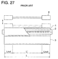
- Fig. 27 shows a block diagram of a conventional fixing device.
- numeral 1 represents a heating roller having heating means 2 inside thereof
- numeral 3 represents a pressure roller which is brought into contact with heating roller 1.
- the transfer sheet on which the toner image has been transferred passes heating roller 1 and pressure roller 3, the toner image is thermally fixed on the transfer sheet.
- the fixing device can fix plural kinds of transfer sheets having different sizes of width, for example, a transfer sheet having a width L and a transfer sheet having a width L'.
- the fixing device having the above-mentioned constitution, for example, if a under-sizedd transfer sheet having a width L' is continuously fixed, there is a possibility that the temperature in the non-passing portion (Lout) of the under-sizedd transfer sheet rises and hot offset occurs.
- cooling roller 4 provided on both ends of heating roller 1 contactably/separably is provided.
- cooling roller When fixing the under-sizedd transfer sheet, cooling roller is brought into contact with heating roller 1 and portions out of the passing region of the under-sizedd transfer sheet is cooled.
- the heating roller is a hard roller laminated with a fluorine-containing resin on a metallic roller substrate and the cooling roller is a metal roller, there is a possibility that the contact area between the heating roller and the cooling roller is narrow so that sufficient cooling is prevented. Accordingly, hot offset easily occurs.
- the temperature on the surface of the cooling roller is lower than the heating roller. Accordingly, contamination on the heating roller easily transfers on the surface of the cooling roller.
- An objective of the invention is to provide a fixing device in which hot offset is difficult to occur.
- a device for fixing a toner image comprises
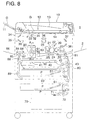
- automatic document feeding device 10 On the upper portion of image forming apparatus 1, automatic document feeding device 10 is provided. Document G set on document loading tray 11 is fed onto document loading plate 14 by means of conveyance mechanism 12. Document G loaded on aforesaid document loading plate 14 is discharged to document receiving section 13 by means of conveyance mechanism 12 at the timing of exposure end.
- drum-shaped photoreceptor 21 which is an image forming means
- charger 22, developing device 23, transfer device 24, separation device 25 and cleaning device 26 are located in accordance with their functions.
- Aforesaid devices are formed integrally as an image forming unit.
- electrostatic latent image is developed in developing device 23 inside image forming unit 20.
- visible image by means of toner image is formed on the surface of photosensitive layer of photoreceptor 21.
- double-sided copying paper feeding unit 40 and paper feeding units 50, 60 and 70 are located vertically.
- paper feeding units 50, 60 and 70 different sizes of recording paper P, used as transfer sheets, are housed.
- two modes i.e., an automatic mode which detects the size of document loaded on document loading plate 14 and automatically selects recording paper P relevantly and a manual mode in which an operator selects recording paper P by the use of a selection switch for recording paper P provided on an operation panel, are provided.
- recording paper P housed in paper feeding unit 50 When recording paper P housed in paper feeding unit 50 is selected, only one sheet of recording paper P is fed by means of paper feeding roller 51. Aforesaid recording paper P is conveyed by the use of guiding roller 52.
- recording paper P housed in paper feeding unit 60 or 70 when recording paper P housed in paper feeding unit 60 or 70 is selected, only one sheet of recording paper P is fed by means of paper feeding roller 61 or 71. Aforesaid recording paper P is conveyed by the use of guiding roller 62 or 72.
- Recording paper P is conveyed to photoreceptor 21 on which toner images are formed, through conveyance path 80 by means of conveyance mechanism 81. Recording paper P is force to temporarily stop by means of registration roller 82 provided in image forming apparatus 1. Paper feeding is conducted in such a manner that toner images formed on photoreceptor 21 coincides with recording paper P.
- toner images on photoreceptor 21 is transferred onto recording paper P by means of transfer device 24.
- Aforesaid recording paper P is withdrawn from the surface of photoreceptor 21 by means of separation device 25.
- Recording paper P is conveyed to fixing device 90 by means of conveyance device 83.
- Fixing device 90 is equipped with heating roller 91 and pressure roller 92 which is brought into contact with aforesaid heating roller 91. Due to that recording paper P on which toner image is transferred is fixed between heating roller 91 and pressure roller 92, toner images are thermally fixed on recording paper P.
- Recording paper P in which fixing is finished is ejected by means of paper ejecting guiding roller 84.
- paper ejecting switching member 85 falls.
- recording paper P is ejected on paper ejecting tray 86.
- paper ejecting switching member 85 rises. Recording paper guiding section 87 is opened. Recording paper P is conveyed to the dashed arrowed line.
- recording paper P is conveyed downward by means of conveyance mechanism 88.
- recording paper reversing section 89 By means of recording paper reversing section 89, aforesaid recording paper P is caused to switch back.
- the trailing end of recording paper P becomes the leading end thereof to be conveyed into double-sided copying paper feeding unit 50.
- Recording paper P moves toward paper feeding direction by means of conveyance belt 41 provided on double-sided copying use paper feeding unit 50.
- paper feeding roller 42 By means of paper feeding roller 42, recording paper P is fed again.
- conveyance roller 43 By means of conveyance roller 43, recording paper P is guided to conveyance path 80.
- recording paper P is conveyed to the direction of photoreceptor 21 again.
- toner images are transferred.
- fixing device 90 the toner image is fixed.
- recording paper P is ejected onto paper ejection tray 86.
- manual paper feeding device 2 which conducts paper feeding manually is also provided in image forming apparatus 1.
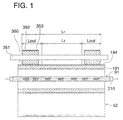
- Fig. 1 shows a cross sectional view of cutting line A-A in Fig. 8 which is an overall block diagram of an image forming apparatus of embodiment of the present invention.
- numeral 191 represents a cylindrical metal layer (metal roller substrate) made of metal cylinder (aluminum alloy) in which both ends are opened.
- halogen heater lamp 210 functioning as a heating source
- fluorine-resin layer 194 functioning as a parting layer
- a halogen heater lamp was used as a heating source.
- a resistrative heating layer may be formed on the outer circumference or inner circumference of the heating roller.
- Numeral 350 represents a cooling roller, functioning as a cooling member, provided in such a manner as to contact a region (Lout: hereinafter, non-passing portion (Lout)) other than the passing region of minimum size recording paper (L2), for example, A4R inside the passing region of the maximum size recording paper P (L1), such as A3R or A4 of heating roller 91.
- Cooling roller 350 is composed of shaft 351 and silicone rubber layer 352 which is formed on shaft 351 and which functions as an elastic member layer being brought into contact with the non-passing portion (Lout) of heating roller 91.
- silicone rubber layer 352 On the outer circumference of aforesaid silicone rubber layer 352, fluorine resin layer 353, functioning as a parting layer, is formed.
- silicone rubber layer 352 was used as an elastic member layer.
- any materials can be used, provided that it is an elastic member having heat conductivity of 0.16 W/mk or more.
- fluorine rubber may be used.
- the layer thickness of fluorine resin layer 353 formed on the outer circumference of cooling roller 350, functioning as a cooling member, is thin. Therefore, aforesaid fluorine resin layer 353 can be regarded as an elastic material layer in combination with silicone rubber layer 352. Contacting area between heating roller 91 and cooling roller 350 becomes wide. Accordingly, cooling of non-passing portion (Lout) of heating roller 350 can be conducted.
- non-passing portion (Lout) of heating roller can further be cooled.
- Fig. 2 shows a cross sectional view of cutting line A-A in Fig. 8 which is an overall block diagram of an image forming apparatus of embodiment of the present invention.
- numeral 291 represents a cylindrical metal layer (metal roller substrate) made of metal cylinder (aluminum alloy) in which both ends are opened.
- halogen heater lamp 210 functioning as a heating source, is provided inside cylindrical metal layer 291.
- silicone rubber layer 292 and fluorine-resin layer 293 are formed on the outer circumference of cylindrical metal layer 291.
- a silicone rubber layer 352 was used as an elastic member layer.
- the kind of the material provided that it is an elastic member having heat conductivity of 0.16 W/mK or more.
- Numeral 355 represents a cooling roller, functioning as a cooling member, provided in such a manner as to contact a region (Lout: hereinafter, non-passing portion (Lout)) other than the passing region of minimum size recording paper (L2), for example, A4R inside the passing region of the maximum size recording paper p (L1), such as A3R or A4 of heating roller 91.
- Cooling roller 355 is composed of shaft 356 and metal roller section 357 which is formed on shaft 356 and which is brought into contact with the non-passing portion (Lout) of heating roller 91. On the outer circumference of aforesaid metal roller section 357, fluorine resin layer 354 is formed.
- the layer thickness of fluorine resin layer 354 formed on the outer circumference of metal roller section 357 of cooling roller 350, functioning as a cooling member, is thin. Therefore, aforesaid fluorine resin layer 354 can be regarded as a metal roller section. Contacting area between heating roller 91 and metal roller section 357 as a cooling member becomes wide. Due to this, heating roller can be cooled. In addition, heating roller 91 can be sufficiently cooled due to using metal roller 357 having high heat conductivity as a cooling member.
- Fig. 3 shows a cross sectional block diagram of the main portion of the fixing device of the present embodiment.
- cooling roller 350 can be brought into contact/withdrawn against heating roller 91 in the present embodiment though, in the first embodiment, cooling roller 350 is fixed and constantly brought into contact with heating roller 91.
- numeral 400 is an approximately L-shape lever rotatably provided on pin 401. At one end of aforesaid lever 400, shaft 351 of cooling roller 350 is fixed. At the other end, elongated hole 402 is provided.
- Pin 407 provided on spindle 406 on solenoid 405 is engaged with elongated hole 402 of lever 400.
- lever 400 rotates with pin 401 as the center.
- Silicone rubber layer 352 on cooling roller 350 is controlled to contact/separate from the non-passing portion (Lout) of heating roller 91.
- PFA (tetrafluoroethylene/perfluoroalkyl vinyl ether copolymer)
- heating roller 91 silicone oil is coated as a release material.
- silicone rubber 352 on cooling roller 350 of the present embodiment fluorine resin layer 353 is formed as a release material. Contact angle by means of fluorie resin layer 353 is larger than the contact angle by means of the release material for PFA layer 194' on the surface of heating roller 91.
- the fluorine rubber or a silicone rubber is used as a parting layer for heating roller 91
- the PFA layer is preferable as a parting layer for cooling roller 350.
- Fig. 4 i a block diagram explaining an electrical constitution of the fixing device shown in Fig. 3.
- numeral 380 represents a heating and driving means composed of a circuit which drives halogen heater lamp 210 and numeral 410 represents a solenoid driving means composed of a circuit which drives solenoid 405.
- Numeral 500 is a control section which obtains temperature information (t1) from first temperature detecting means 340 which detects temperature of the passing region of the minimum size recording paper of heating roller 91, temperature information (t2) from second temperature detecting means 341 which detects the temperature of non-passing portion (Lout) of heating roller 91, a driving order sent from an image forming apparatus main body when the power supply switch for the image forming apparatus main body is turned ON, a copying order sent from an image forming apparatus main body when the power supply switch for the image forming apparatus main body is turned ON, information about the size of recording paper (W) and information about the set copying sheet.
- Numeral 500 drives halogen heater lamp 210 through heating and driving means 380 and solenoid 405 through solenoid driving means 410.
- Fig. 5(a) represents a flow diagram explaining an overall operation of the image forming apparatus.
- Fig. 5(b) is a flow diagram explaining warming up operation in Fig. 5(a).
- Fig. 5(c) is a flow diagram explaining idling operation in Fig. 5(a).
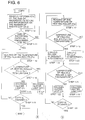
- Figs. 6 and 7 respectively represent a flow diagram explaining operation of the fixing device when copying shown in Fig. 3.
- Step 1-1 When the power supply switch is turned ON, warming up, i.e., the temperature of heating roller 91 is raised to be the prescribed temperature is conducted (Step 1-1).
- Steps 1-2 and 1-3 Wen warming up is completed, idling, i.e., an operation to maintain the temperature of heating roller 91 at a prescribed one is conducted (Steps 1-2 and 1-3).
- Step 1-4 When the copy button is turned ON, copying is conducted (Step 1-4). When copying is finished, the step is returned to Step 1-2. Until the next copy button is turned ON, idling is conducted.
- Control section 500 obtains information about temperature (t1) from first temperature detecting means 340. If temperature of heating roller 91 (t1) is lower than prescribed temperature (T), halogen heater lamp 210 is driven until the temperature is raised at prescribed temperature (T) or higher. When the temperature reaches the prescribed temperature (T) or higher, the driving stops.
- Control section 500 obtains information about temperature (t1) from first temperature detecting means 340 of heating roller 91. If temperature of heating roller 91 (t1) is lower than prescribed temperature (T), halogen heater lamp 210 is driven (Steps 1-7 and 1-8) until the temperature is raised at prescribed temperature (T) or higher. When reached it, the driving stops (Steps 1-7 and 1-9).
- an operator inputs information about the size of recording paper (W) and information about the number of copying sheet (I) on the apparatus. If the copy button is turned ON, copying starts.
- Control section 500 reads information about the size of recording paper (W) and information about the number of copying sheet (I) (Step 1-10), and conducts copying for the number of copy set.
- controlling operation is significantly different between when the size of recording paper P passed (W) is larger than the size determined prescribedly (W) and when it is lower than the size determined prescribedly (Step 1-11).
- Step 1-12 information about the temperature from first temperature detection means 340 (t1) is obtained (Step 1-12).
- Halogen heater lamp 210 is caused to be actuated in such a manner that temperature (T) set of heating roller 91 is the same or higher than set temperature (T) (Steps 1-13, 1-14 and 1-15).
- Copying for the set number of sheet (I) is conducted (Step 1-16), and return to Step 1-2 in Fig. 5(a).
- control section 500 obtains information about the temperature from first and second temperature detection means 340 and 341 (t1 and t2) (Step 1-17). If the temperature of non-passing portion (Lout) (t2) is higher than the prescribed one, solenoid 405 is actuated so that cooling roller 350 is brought into contact with heating roller 91 (Steps 1-18 and 1-19). In addition, if the temperature of the non-passing portion (Lout) (t2) is at the prescribed temperature or less, solenoid 405 is actuated so that cooling roller 350 is withdrawn from heating roller 91 (Steps 1-18 and 1-20).
- halogen heater lamp 210 is caused to be actuated in such a manner that the temperature of heating roller 91 (t1) is at the set one (T) or higher (Steps 1-21, 1-22 and 1-23). Thus, copying for set number of sheets (I) is conducted (Step 1-24).
- cooling roller 350 is brought into contact with heating roller 91 when copying for the set number of sheets is finished (Step 1-19). In this occasion, cooling roller 350 is withdrawn from heating roller 91 (Steps 1-25 and 1-26), and return to Step 1-2 in Fig. 5(a).
- control means 500 obtains information about the size of recording paper (W). If a recording paper conducting image formation is smaller than the prescribed size, due to that cooling roller 350 is caused to be brought into contact/withdrawn from heating roller 91 and that the temperature of non-passing portion (Lout) is not raised compared with prescribed temperature (TO), temperature rise in the non-passing portion (Lout) of heating roller 91 can be prevented.
- the layer thickness of fluorine resin layer 353 formed on the outer circumference of cooling roller 350, functioning as a cooling member, is thin. Therefore, aforesaid fluorine resin layer 353 can be regarded as an elastic material layer in combination with silicone rubber layer 352. Contacting area between heating roller 91 and cooling roller 350 becomes wide. Accordingly, cooling of non-passing portion (Lout) of heating roller 350 can be conducted.
- cooling roller 350 Accordingly, contamination is not laminated on the surface of cooling roller 350. Contact with heating roller 91 is constantly maintained, and cooling efficiency is not reduced.
- heated cooling roller 350 can abruptly be cooled due to separating cooling roller 350 from heating roller 91. Cooling effects are not reduced and, in addition, adhesion of contamination from the heating roller can be reduced.
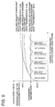
- the present inventors studied the change of temperature in the non-passing portion (Lout) when recording papers having small size were continuously copied, when cooling rollers made of PET in which the heat conductivity of the surface materials were respectively 0.08 W/mK and 0.16 W/mK were constantly brought into contact with heating rollers as shown in the first and the second embodiment and when cooling roller 350 made of carbon steel whose transmission ratio was 48.5 W/mK was brought into contact/withdrawn with heating roller 91.
- Fig. 9 shows the reslts thereof.
- cooling roller 350 was constantly brought into contact with heating roller 91, it was confirmed that the temperature of the non-passing portion (Lout) can be maintained at 240°C (which is the hot offset occurrence temperature) or less even when copying is conducted continuously, provided that the heat conductivity on the surface of the cooling roller.
- cooling roller 350 As in the third Embodiment, if cooling roller 350 is brought into contact/withdrawn on heating roller 91, it was confirmed that the temperature of the non-passing portion (Lout) in the vicinity of the prescribed temperature (TO: 220°C) set lower than 240°C (which is the hot offset occurrence temperature).
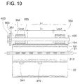
- FIG. 10 shows a cross sectional view of the fixing device of the fourth embodiment. Parts having the same numbers as those in the fixing device of Fig. 1 is so structured to be iexplained in the first embodiment.
- numeral 340 represents the first temperature detecting means which detects temperature (t1) of the passing region on heating roller 91 for a recording paper with the minimum size.
- Numeral 341 represents the second temperature detecting means which detects temperature (t2) of the non-passing region (Lout) on heating roller 91.
- numeral 400 is an approximately L-shape lever rotatably provided on pin 401. At one end of aforesaid lever 400, shaft 351 of cooling roller 350 is fixed. At the other end, elongated hole 402 is provided.
- Pin 407 provided on spindle 406 on solenoid 405 is engaged with elongated hole 402 of lever 400.
- lever 400 rotates with pin 401 as the center.
- Silicone rubber layer 352 on cooling roller 350 is controlled to contact/separate from the non-passing portion (Lout) of heating roller 91.
- first gear 800 is mounted on shaft 351.
- first gear 800 is engaged with second gear 801 which is rotated by auxiliary cooling motor 344 (not illustrated).
- Fig. 12 shows a block diagram explaining electrical constitution of the fixing device shown in Fig. 10.
- Control section 500 of the fourth embodiment having the same function as control section 500 of the third embodiment, further actuates auxiliary cooling motor 344 through auxiliary cooling motor driving means 345.
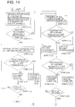
- Fig. 13(a) shows a flow diagram explaining overall explanation of an image forming apparatus
- Fig. 13(b) shows a flow diagram explaning warming up operation in Fig. 13(a)
- Fig. 13(c) shows a flow diagram explaining idling operation in Fig. 13(b).
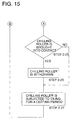
- Figs. 14 and 15 respectively show a flow diagram showing control of the fixing device during copying operation in Fig. 10.
- Steps through 2-1 through 2-26 provide the same operation as Steps 1-1 trough 1-26 in Figs. 5(a), 5(b), 5(c), 6 and 7 in the first embodiment.
- auxiliary cooling motor 344 is actuated so that cooling roller 350 is subjected to idling for a prscribed time. Then, return to Step 2-2 in Fig. 13(a).
- auxiliary cooling motor 344 which is an auxiliary cooling means, is actuated so that cooling roller 350 is subjected to idling rotation. Due to this, cooling roller 350 is cooled.
- cooling roller 350 is cooled. Therefore, the rise of the temperature of non-passing portion of heating roller 91 can be prevented. Hot offset is difficult to occur. Accordingly, durability of parts in the vicinity of the heating roller 91can be maintained.
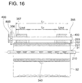
- FIG. 16 shows a cross sectional view of the fixing device of the fifth embodiment.
- This fixing device is so structured to be iexplained in the second embodiment.
- identical numerals are affixed. Their explnation will be omitted.
- Control section 500 of the fifth embodiment having the same function as control section of the fourth embodiment, further actuates auxiliary cooling motor 344 through auxiliary cooling motor driving means 345.
- look-up table 600 is provided.
- loo-up table 600 memorizes relationship between the size of the recording paper and cooling means contacting starting sheet number (i). As the width of the recording paper is narrow, volume of colory not absorbed by recording paper P on non-passing portion (Lout) is large. Rise of the temperature of non-passing portion (Lout) becomes larger. Hot offset occurs earlier. Cooling means contacting starting sheet number (i) becomes earlier.
- aforesaid look-up table alo memorizes relationship between copying number set when the cooling roller is subjected to idling after copying is finished and the time for idling of the cooling roller.
- Control means 500 obtains information about the size of recording paper (W) and information about the nmber of copying (I) (Step 3-10), and copying for the set number of sheet will be conducted.
- contol operation is noticeably different between a case when the size of recording paper P passed (W) is larger than the prescribed size determined in advance (W) and a case when the size of recording paper P passed (W) is the same as the prescribed size (W) or smaller (Step 11).
- Step 3-12 If the size of recording paper P passed (W) is larger than the size determined prescribedly (W) (Step 3-12), at a certain cycle, information about the temperature from first temperature detection means 340 (t1) is obtained (Step 3-13).
- Halogen heater lamp 210 is caused to be actuated in such a manner that temperature (T) set of heating roller 91 is the same or higher than set temperature (T) (Steps 3-14, 3-15 and 3-16). Copying for the set number of sheet (I) is conducted (Step 17), and return to Step 2-2 in Fig. 13(a).
- control section 500 determines cooling means contacting starting sheet number (i) (Step 3-18).
- Step 3-19 information about the number o sheets copied continuously (x) is read (Step 3-19) and temperature information (t) from temperature detecting means 340 is obtained (Step 3-20).
- temperature information (t) from temperature detecting means 340 is obtained (Step 3-20).
- halogen heater lamp 210 is actuated (Step 3-21, 3-22 and 3-23).
- cooling roller 355 is brought into contact with heating roller 91 (Steps 3-24 and 3-25).
- Step 3-26 When copying for the set sheet number is finished (Step 3-26), there may be cases that cooling roller 355 is brought into contact with heating roller 91 (Step 3-25). In such cases, cooling roller 355 is withdrawn from heating roller 91 (Steps 3-27 and 3-28).
- idling time of cooling roller 350 is determined.
- Auxiliary cooling motor 344 is driven. Cooling roller 350 is subjected to idling for a prescribed time (Step 3-29). Then, return to Step 2 in Fig. 13(a).
- control means 500 obtains information from the transfer sheet size selection means. If the recording paper on which images are formed is smaller than the prescribed size, in copying on and after cooling means contacting starting sheet number (i), rise of the temperature of the non-passing portion (Lout) of heating roller 91 is prevented due to contacting cooling roller 355 with heating roller 91.
- auxiliary cooling motor 344 which is an auxiliary cooling means, is driven so that cooling roller 355 is subjected to idling. Thus, cooling roller 355 is cooled.
- cooling roller 355 is cooled even when a recording paper whose size is smaller than the prescribed size is continuously copied successively, the rise of the temperature of non-passing region of heating roller 91 can be prevented. Accordingly, hot offset is dificult to occur and durability of parts in the vicinity of the heating roller can be maintained.
- look-up table 600 memorizes relationship between set copy number and the idling time for the cooling roller. Due to this, idling time for cooling roller 355 has been determined in accordance with the set copy number. Accordingly, cooling roller 355 can be determined surely. In addition, there i no waste idling. Therefore, energy saving is attained.
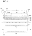
- Fig. 21 shows a cross sectioal vie of the fixing device of the present embodiment.
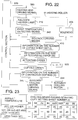
- Fig. 22 shows a block diagram explaining an electrical constitution of the fixing device shown in Fig. 21.
- table 600 of the sixth embodiment records relationship between the size of recording paper P and cooling means contacting starting sheet number (i) and ambient temperature (t').
- th size of the recording paper is the same, the higher the temperature (t') inside the apparatus is, the higher the temperature of recording paper P is. Therefore, calory removed from heatng roller 91 when a paper is passed becomes small. Therefore, temperature difference with the temperature of non-passing portion L1 on heating roller 91 becomes small. As a result, cooling means contacting starting sheet number becomes delayed.
- aforesaid look-up table also memorizes relationship between copying number set when the cooling roller is subjected to idling after copying is finished and the time for idling of the cooling roller.
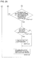
- Control means 500 obtains information about the size of recording paper (W) and information about the number of copying (I) (Step 4-10), and copying for the set number of sheet will be conducted.
- contol operation is noticeably different between a case when the size of recording paper P passed (W) is larger than the prescribed size determined in advance (W) and a case when the size of recording paper P passed (W) is the same as the prescribed size (W) or smaller (Step 11).
- Step 4-12 information about continuous copying sheet number is read (Step 4-12), and information about the temperature from first temperature detection means 340 (t) is obtained (Step 4-13).
- Halogen heater lamp 210 is caused to be actuated in such a manner that temperature (T) set of heating roller 91 is the same or higher than set temperature (T) (Steps 4-14, 4-15 and 4-16). Copying for the set number of sheet (I) is conducted (Step 4-17), and return to Step 2-2 in Fig. 13(a).
- control section 500 determines cooling means contacting starting sheet number (i) (Step 4-19).
- Step 4-20 information about the number of sheets copied continuously (x) is read (Step 4-20) and temperature information (t) from temperature detecting means 340 is obtained (Step 4-21).
- temperature information (t) from temperature detecting means 340 is obtained (Step 4-21).
- halogen heater lamp 210 is actuated (Step22, 23 and 24).
- cooling roller 355 is brought into contact with heating roller 91 (Steps 4-25 and 4-26).
- Step 4-27 When copying for the set sheet number is finished (Step 4-27), there may be cases that cooling roller 355 is brought into contact with heating roller 91 (Step 4-26). In such cases, cooling roller 355 is withdrawn from heating roller 91 (Steps 4-28 and 4-29).
- idling time of cooling roller 350 is determined.
- Auxiliary cooling motor 344 is driven. Cooling roller 350 is subjected to idling for a prescribed time (Step 4-30). Then, return to Step 2-2 in Fig. 13(a).
- control means 500 obtains information from the transfer sheet size selection means. If the recording paper on which images are formed is smaller than the prescribed size, in copying on and after cooling means contacting starting sheet number (i), rise of the temperature of the non-passing portion (Lout) of heating roller 91 is prevented due to contacting cooling roller 355 with heating roller 91.
- cooling means driving stating number (i) and ambient temperature (t') due to adding the relationship between cooling means driving stating number (i) and ambient temperature (t') to the table, cooling means contacting starting sheet number (i) can be determined more correctly. As a result, temperature change of heqating roller 91 in the axis direction can be minimal.
- the present invention is not limited to the above-mentioned embodiments.
- the ambient condition temperature inside the apparatus was used.
- humidity inside the apparatus may be used.
- the cooling means driving starting sheet number may be determined by the use of both temperature and humidity inside the table apparatus as the ambient conditions.
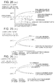
- the present inventors continuously copied under-sizedd recording papers when the cooling means is used and when not used, so that temperature of non-passing portion (Lout) of heating roller 91 was investigated.
- the cooling roller functioning as a cooling member, has an elastic layer on the outer circumference, the contact area between the heating roller and the cooling member is broadened. Accordingly, cooling of the heating roller can be conducted and the occurrence of hot offset can be prevented.
Landscapes
- Physics & Mathematics (AREA)
- General Physics & Mathematics (AREA)
- Fixing For Electrophotography (AREA)
Applications Claiming Priority (4)
| Application Number | Priority Date | Filing Date | Title |
|---|---|---|---|
| JP34622897 | 1997-12-16 | ||
| JP9346228A JPH11174897A (ja) | 1997-12-16 | 1997-12-16 | 画像形成装置 |
| JP35278097A JPH11184288A (ja) | 1997-12-22 | 1997-12-22 | 定着装置 |
| JP35278097 | 1997-12-22 |
Publications (2)
| Publication Number | Publication Date |
|---|---|
| EP0924577A2 true EP0924577A2 (de) | 1999-06-23 |
| EP0924577A3 EP0924577A3 (de) | 2000-07-26 |
Family
ID=26578225
Family Applications (1)
| Application Number | Title | Priority Date | Filing Date |
|---|---|---|---|
| EP98310195A Withdrawn EP0924577A3 (de) | 1997-12-16 | 1998-12-11 | Fixiervorrichtung |
Country Status (2)
| Country | Link |
|---|---|
| US (1) | US5991565A (de) |
| EP (1) | EP0924577A3 (de) |
Families Citing this family (11)
| Publication number | Priority date | Publication date | Assignee | Title |
|---|---|---|---|---|
| US6400913B1 (en) * | 2000-12-14 | 2002-06-04 | Xerox Corporation | Control registration and motion quality of a tandem xerographic machine using transfuse |
| US7054572B2 (en) * | 2003-03-31 | 2006-05-30 | Eastman Kodak Company | Method and apparatus for selective fuser rolling cooling |
| US20050089343A1 (en) * | 2003-10-27 | 2005-04-28 | Eastman Kodak Company | Heat sinking fuser rolls to reduce thermal transients |
| JP4522138B2 (ja) * | 2004-05-07 | 2010-08-11 | キヤノン株式会社 | 加熱定着装置 |
| US7764892B2 (en) * | 2007-11-14 | 2010-07-27 | Xerox Corporation | Uniform gloss control apparatus and method |
| US8457513B2 (en) * | 2010-02-09 | 2013-06-04 | Eastman Kodak Company | Selective cooling of a fuser |
| US8265505B2 (en) * | 2010-02-09 | 2012-09-11 | Eastman Kodak Company | Selective cooling of a fuser heater roller |
| JP6000706B2 (ja) * | 2012-07-18 | 2016-10-05 | キヤノン株式会社 | 画像加熱装置 |
| JP6108730B2 (ja) * | 2012-09-04 | 2017-04-05 | キヤノン株式会社 | 定着装置 |
| JP2014178469A (ja) * | 2013-03-14 | 2014-09-25 | Ricoh Co Ltd | 定着装置及び画像形成装置 |
| US10156821B1 (en) * | 2017-09-21 | 2018-12-18 | Kabushiki Kaisha Toshiba | Image forming apparatus and image forming method |
Family Cites Families (9)
| Publication number | Priority date | Publication date | Assignee | Title |
|---|---|---|---|---|
| JPS5984272A (ja) * | 1982-11-05 | 1984-05-15 | Konishiroku Photo Ind Co Ltd | 熱ロ−ラ定着装置 |
| US4512650A (en) * | 1983-11-04 | 1985-04-23 | Eastman Kodak Company | Fuser apparatus having a uniform heat distribution |
| JPS6190178A (ja) * | 1984-10-09 | 1986-05-08 | Fuji Xerox Co Ltd | 定着装置 |
| JPH01221779A (ja) * | 1988-02-29 | 1989-09-05 | Canon Inc | 定着装置 |
| JPH06242701A (ja) * | 1993-02-19 | 1994-09-02 | Fuji Xerox Co Ltd | 定着装置 |
| US5561512A (en) * | 1995-01-11 | 1996-10-01 | Mita Industrial Co. Ltd. | Fixation control device |
| US5729813A (en) * | 1995-03-27 | 1998-03-17 | Xerox Corporation | Thin, thermally conductive fluoroelastomer coated fuser member |
| JP3658055B2 (ja) * | 1995-10-12 | 2005-06-08 | キヤノン株式会社 | 画像形成装置の電源制御装置 |
| US5787321A (en) * | 1996-02-09 | 1998-07-28 | Asahi Kogaku Kogyo Kabushiki Kaisha | Temperature controlling device for fixing unit |
-
1998
- 1998-12-10 US US09/209,021 patent/US5991565A/en not_active Expired - Fee Related
- 1998-12-11 EP EP98310195A patent/EP0924577A3/de not_active Withdrawn
Also Published As
| Publication number | Publication date |
|---|---|
| US5991565A (en) | 1999-11-23 |
| EP0924577A3 (de) | 2000-07-26 |
Similar Documents
| Publication | Publication Date | Title |
|---|---|---|
| US4998121A (en) | Image forming apparatus | |
| JP4048694B2 (ja) | 定着装置 | |
| US4145599A (en) | Fixing device of electrophotographic copying machine | |
| US7421220B2 (en) | Image forming apparatus with fixing control based on recording material type | |
| US5991565A (en) | Fixing device | |
| EP0962837A2 (de) | Gerät und Verfahren zur Fixierung von Tonerbildern auf ein Aufzeichnungsmedium | |
| JP2004326098A (ja) | 定着装置、画像形成装置及び定着方法 | |
| US8346112B2 (en) | Cooling member included fixing device and image forming apparatus | |
| JP3373419B2 (ja) | 定着方法および定着装置 | |
| EP0432687B1 (de) | Bildfixiergerät | |
| US5089857A (en) | Electrostatographic apparatus having sheet cooling and turnover devices | |
| JP3806027B2 (ja) | 画像形成装置の定着温度制御方法 | |
| US5289248A (en) | Fixing unit and image forming apparatus having the same | |
| JP3017604B2 (ja) | 定着装置及び画像形成装置 | |
| EP0070740B1 (de) | Fixier- und Heizvorrichtung für ein elektrostatisches Kopiergerät | |
| US20030202814A1 (en) | Thermal fixing device and image forming apparatus using the same | |
| JPH0887191A (ja) | 定着装置 | |
| JP3226967B2 (ja) | 定着装置 | |
| EP0369378B1 (de) | Bildfixiergerät | |
| JP3599087B2 (ja) | 画像形成装置の定着装置の制御方法 | |
| JPH11174877A (ja) | 画像形成装置の制御方法及び画像形成装置 | |
| JPH11184288A (ja) | 定着装置 | |
| JP3771486B2 (ja) | 定着装置及びその定着装置を備えた画像形成機 | |
| JPH11174897A (ja) | 画像形成装置 | |
| JPH0656537B2 (ja) | 記録装置 |
Legal Events
| Date | Code | Title | Description |
|---|---|---|---|
| PUAI | Public reference made under article 153(3) epc to a published international application that has entered the european phase |
Free format text: ORIGINAL CODE: 0009012 |
|
| AK | Designated contracting states |
Kind code of ref document: A2 Designated state(s): AT BE CH CY DE DK ES FI FR GB GR IE IT LI LU MC NL PT SE |
|
| AX | Request for extension of the european patent |
Free format text: AL;LT;LV;MK;RO;SI |
|
| PUAL | Search report despatched |
Free format text: ORIGINAL CODE: 0009013 |
|
| AK | Designated contracting states |
Kind code of ref document: A3 Designated state(s): AT BE CH CY DE DK ES FI FR GB GR IE IT LI LU MC NL PT SE |
|
| AX | Request for extension of the european patent |
Free format text: AL;LT;LV;MK;RO;SI |
|
| AKX | Designation fees paid | ||
| STAA | Information on the status of an ep patent application or granted ep patent |
Free format text: STATUS: THE APPLICATION IS DEEMED TO BE WITHDRAWN |
|
| 18D | Application deemed to be withdrawn |
Effective date: 20010127 |
|
| REG | Reference to a national code |
Ref country code: DE Ref legal event code: 8566 |